patent · US5483950
Solar device with an air receiver and air return
16 January 1996
Page 1 — bibliographic record
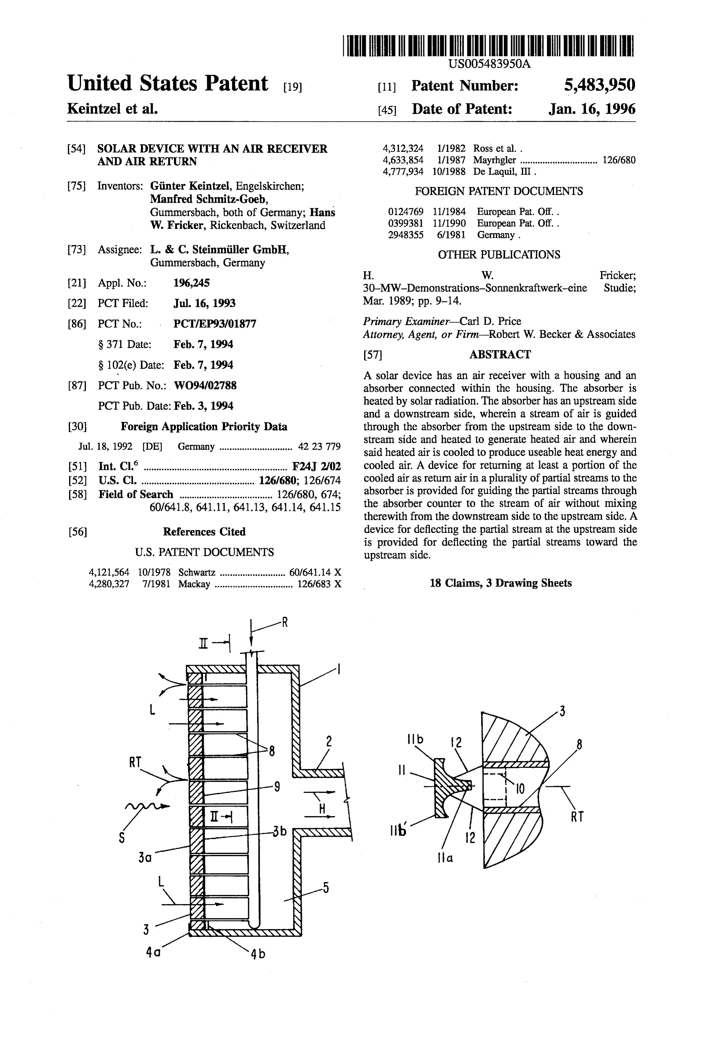
United States Patent 19 11 Patent Number: 5,483,950 Keintzel et al. 45 Date of Patent: Jan. 16, 1996
54 SOLAR DEVICE WITH AN AIR RECEIVER 4,312,324 1/1982 Ross et al. . AND AIR RETURN 4,633,854 1/1987 Mayrhgler ............................... 126/680
75) Inventors: Manfred
Ginter Keintzel, Engelskirchen;
FOREIGN PATENT DOC
DOCUMENTS
Gummersbach, both of Germany; Hans 0.124769 11/1984 European Pat. Off..
W. Fricker, Rickenbach, Switzerland 0399381 11/1990 European Pat. Off..
73) Assignee: L. & C. Steinmiller GmbH, OTHER PUBLICATIONS Gummersbach, Germany
H. W. Fricker;
21 Appl. No.: 196,245 30-MW-Demonstrations-Sonnenkraftwerk-eine Studie; (22) PCT Filed: Jul. 16, 1993 Mar. 1989; pp. 9-14.
86 PCT No.: PCT/EP93/01877 Primary Examiner-Carl D. Price
Attorney, Agent, or Firm-Robert W. Becker & Associates
A solar device has an air receiver with a housing and an 87 PCT Pub. No.: WO94/02788 absorber connected within the housing. The absorber is PCT Pub. Date: Feb. 3, 1994 heated by solar radiation. The absorber has an upstream side - kW are avy and a downstream side, wherein a stream of air is guided 30 Foreign Application Priority Data through the absorber from the upstream side to the down 42 23 779 stream side and heated to generate heated air and wherein
Jul. 18, 1992 (DE) Germany ...... said heated air is cooled to produce useable heat energy and (51) Int. Cl. ....................... ... F24, 2/02 cooled air. A device for returning at least a portion of the 52 U.S. Cl. .................. . . 126/680; 126/674 cooled air as return air in a plurality of partial streams to the 58) Field of Search ..................................... 126/680, 674; absorber is provided for guiding the partial streams through 60/641.8, 641.11, 641.13, 641.14, 641.15 the absorber counter to the stream of air without mixing therewith from the downstream side to the upstream side. A (56) References Cited device for deflecting the partial stream at the upstream side is provided for deflecting the partial streams toward the
4,121,564 10/1978 Schwartz .......................... 60/641.14 X 4,280,327 7/1981 Mackay ............................... 126/683 X 18 Claims, 3 Drawing Sheets
YYYYYYYYYYYYYYY
Page 2
Drawing sheet — no readable text.
Page 3
Drawing sheet — no readable text.
Page 4
Drawing sheet — no readable text.
Page 5
SOLAR DEVICE WITH AN AR RECEIVER therewith from the downstream side to the upstream AND AR RETURN side; and means for deflecting the partial stream at the upstream
BACKGROUND OF THE INVENTION side such that the partial streams are deflected toward the upstream side.
The invention relates to a solar device in which an air Expediently, for a uniform distribution of the partial stream is guided through and heated by an absorber of an air streams over the upstream side the return air is divided into receiver that is heated by solar radiation, the heated air partial streams of different strengths. Preferably, each of the stream is cooled by removing useful heat energy, especially partial streams exiting from the absorber at the upstream by generating steam, and at least a portion of the cooled air 10 side is forcibly deflected.
stream is returned in a plurality of partial streams to the Advantageously, the means for returning includes a return upstream side of the absorber. air distributor connected within the housing downstream of From CH-Z“Technische Rundschau Sulzer'3/1989, P. 9 the absorber in a flow direction of the heated air. The return 14, especially FIG. 10, such a solar device is known in which air distributor is preferably spaced at a predetermined dis the not completely cooled air is guided from the steam 15 tance from the absorber and has a size that corresponds generator into a warm air chamber upstream of the absorber. substantially to a size of an end face of the absorber facing From there the air flows through suitable nozzles toward the the return air distributor. The return air distributor comprises absorber. It is stated that, for example, 60% of the not outlet openings distributed in a predetermined manner about completely cooled heated air is returned into the circuit. A the return air distributor. The return air distributor further similar device is known from EP 399 381 A1 in which the 20 has for each outlet opening one return pipe, the return pipes outer edges of the absorber are also surrounded by a warm connected to the outlet openings and extending to the air chamber. In this arrangement a protective air stream is upstream side of the absorber. provided in front of the return air for preventing heat loss, In a preferred embodiment of the present invention, the which protective air stream flows to the exterior. outlet openings are substantially uniformly distributed. With respect to the technology of an air receiver reference 25 Preferably, the means of deflecting comprises a deflecting is further made to EP 124 769 B1. member for each return pipe. Each return pipe has a mouth, In the known method it is thus desired to return the air and the deflecting members are positioned at the mouth of cooled by removal of useful heat energy, especially by the return pipes. Preferably, the deflecting member serves also as a radiation protection device for the mouth of the generating steam, which cooled air still contains a consid 30 return erable amount of detectable heat, be returned to the receiver pipe.
substantially completely so that the air sucked through the The deflecting member is preferably mushroom-shaped and has receiver is preheated. In the known arrangements a warm air return pipe. a leg extending toward a center of the mouth of the channel is arranged about the absorber from which the warm The mushroom-shaped deflecting member is return air is blown toward the surface of the receiver that is preferably of a massive construction. In a preferred embodiment of the present invention, a radiated by the sun. In the known arrangement it is difficult 35 chamber to distribute the returned warm air corresponding to the is positioned within the housing adjacent to the radiation intensity profile that is present at the absorber over downstream side of the absorber. The mushroom-shaped the entire receiver surface, especially when during operation deflecting member has a head and a leg, wherein the head comprises an air-permeable absorbent material and the legis of the device a strong wind is present and/or the upstream 40 hollow and connected to the chamber. side of the absorberis relatively large. It should be noted that In another embodiment of the present invention, the for a solar device having a steam output of 100 MW the deflecting member is a plate that is spaced at a distance from receiver must have a diameter of approximately 15 m. the mouth.
It is therefore an object of the present invention to provide The deflecting member preferably consists of a radiation a solar device of the aforementioned kind in which a desired 45 impermeable material or of a material that is partially distribution of the returned air across the upstream side of radiation-impermeable.
the receiver is achieved without substantially affecting the When the deflecting member is radiation-permeable, the efficiency with respect to the conversion of solar radiation to return pipe further comprises a plug inserted into the mouth, heat. the plug consisting of an absorbent material. 50 The absorber is advantageously comprised of individual
SUMMARY OF THE INVENTION absorber modules, and the return pipes serve as holding The solar device according to the present invention is elements for the absorber modules. primarily characterized by: For adapting the partial stream to a solar radiation profile, the return pipes expediently have different diameters or, in an air receiver comprising a housing and an absorber 55 the alternative, connected within the housing, the absorber heated by the returnpipes have identical diameters and solar radiation;
comprise nozzle inserts of different bores.
The return air distributor is expediently comprised of an the absorber having an upstream side and a downstream air inlet pipe (central pipe) penetrating the housing and side, wherein a stream of air is guided through the extending radially within the housing and further comprised absorber from the upstream side to the downstream side 60 of transverse pipes (branch pipes) extending perpendicularly and heated to generate heated air and wherein the from the air inlet pipe in a common radial plane to both sides heated air is cooled to produce useful heat energy and of the air inlet pipe, wherein the outlet openings are posi cooled air, tioned at the inlet pipe and at the transverse pipes in a means for returning at least a portion of the cooled air as predetermined distribution.
return airin a plurality of partial streams to the absorber 65 This object is solved by guiding the partial streams of the such that the partial streams are guided through the return air counter to the cold air stream without mixing absorber counter to the stream of air without mixing therewith from the downstream side of the absorber in a
Page 6
predetermined distribution through the absorber and by According to CH-Z "Technische Rundschau Sulzer", deflecting the partial stream at the upstream side of the page 12, right column, first paragraph, the absorber may be absorber in the direction toward the upstream side. manufactured of square absorber modules of wire mesh In this manner a predetermined distribution of the return strips etc. whereby each absorber module is provided with air over the entire surface of the upstream side of the an aperture plate at the downstream side having openings for receiver is achieved without shading parts of the upstream determining the amount of air flowing through the absorber side with respect to the solar radiation with a distributing. module. With such a measure, a further adaptation possibil Simultaneously, the return air exits in close vicinity to the ity for the radiation intensity profile is provided. upstream side and is sucked from there into the receiver. In such an arrangement it is advantageous that the return Cold air from the surroundings is substantially prevented 10 pipes are simultaneously used as holding elements for the from flowing into the receiver. absorber modules. For adaptation of the partial streams to Naturally, a radiation intensity profile with varying radia the required amount of air pursuant to the radiation profile, tion is observed at the surface of the receiver. It is thus advantageous, when a uniform distribution of the partial the return pipes of the return air distributer may have streams over the upstream side is present, that the return air different diameters or returnpipes of identical diameter may be divided into partial streams of different strengths in order 15 be provided with nozzles of different bores inserted into their to guide the return air in required volumes to the location mouth. When arranged in groups, the return pipes, of course, where it is needed for heat removal. An adaptation can also may have nozzles of identical diameters. be achieved by a non-uniform distribution of partial streams The return air distributer can preferably be comprised of of identical strength. an air inlet pipe, extending radially within the housing and When in addition to the return air the receiver also sucks 20 penetrating the housing of the air receiver, and transverse in cold air to a substantial amount, the deflection of the tubes extending transverse to the air inlet pipe in the form of partial streams can be achieved solely by the vacuum a Christmas tree, whereby in the air inlet pipe and in the generated by the absorber in sucking in the cold air stream. transverse pipe outlet openings are provided in a predeter For the desired object of sucking in only a minimal amount mined, preferably uniform, distribution. Of course, other of cold air and to circulate only return air within the circuit, 25 embodiments are possible, for example, a plurality of air it is however expedient when each partial stream exiting at inlet pipes may be provided that uniformly supply only one the upstream side of the absorber is subjected to a forcible sector of the housing cross-section. deflection.
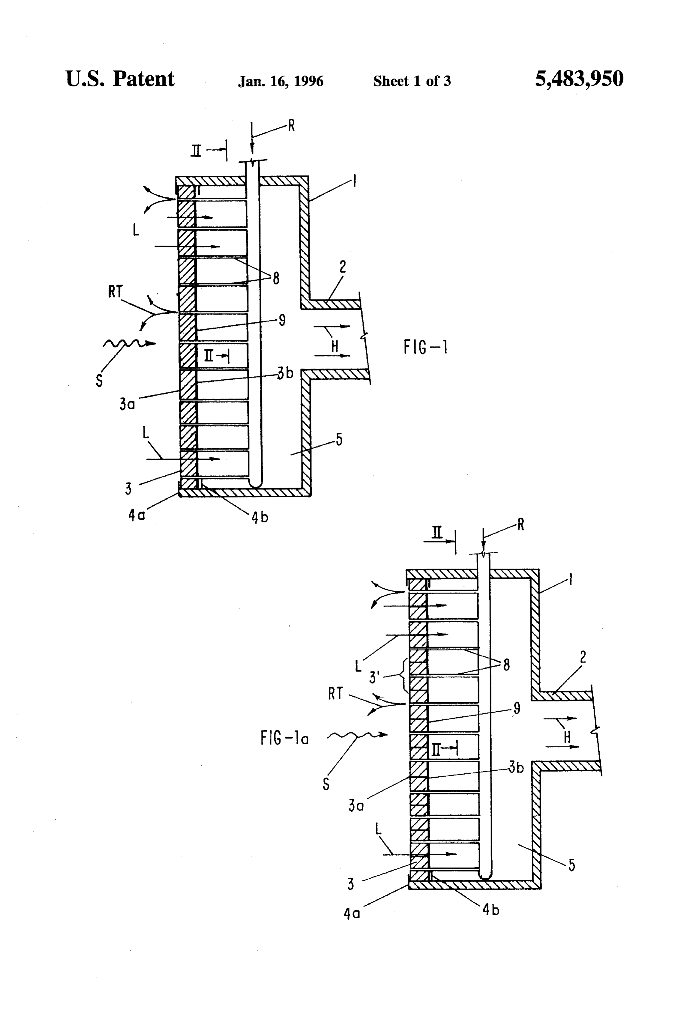
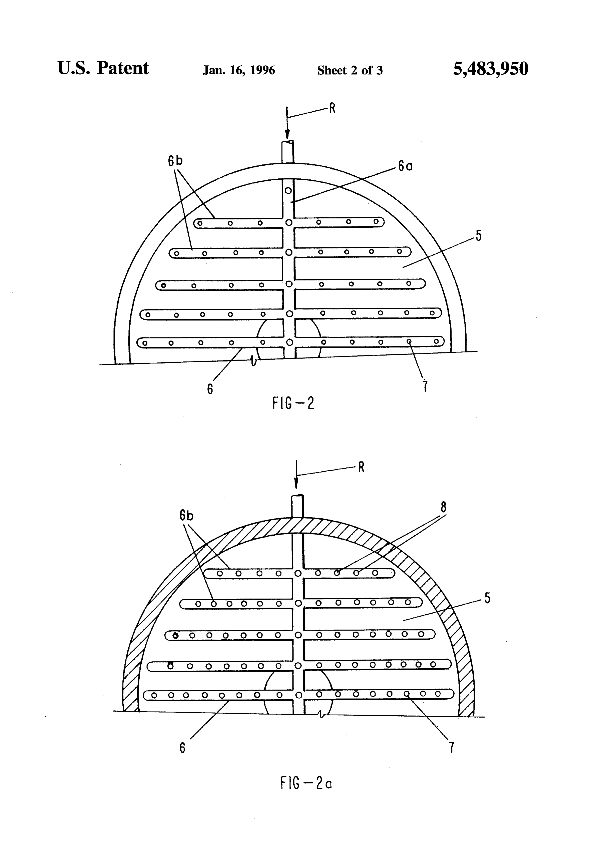
A very simple design of the inventive solar device is BRIEF DESCRIPTION OF THE DRAWINGS provided when the housing of the air receiver containing the 30 absorber has arranged therein a return air distributer which The invention will be described with the aid of the is positioned behind the absorber in the flow direction of the attached FIGS. 1 to 6 in greater detail. It is shown in: heated air stream and placed at a predetermined distance FIG. 1 alongitudinal section of the inventive air receiver; from it and which covers a surface area of the absorber, FIG. 2 a partial section viewed in the direction of arrow whereby its outlet openings are distributed in a predeter 35 II-II in FIG.
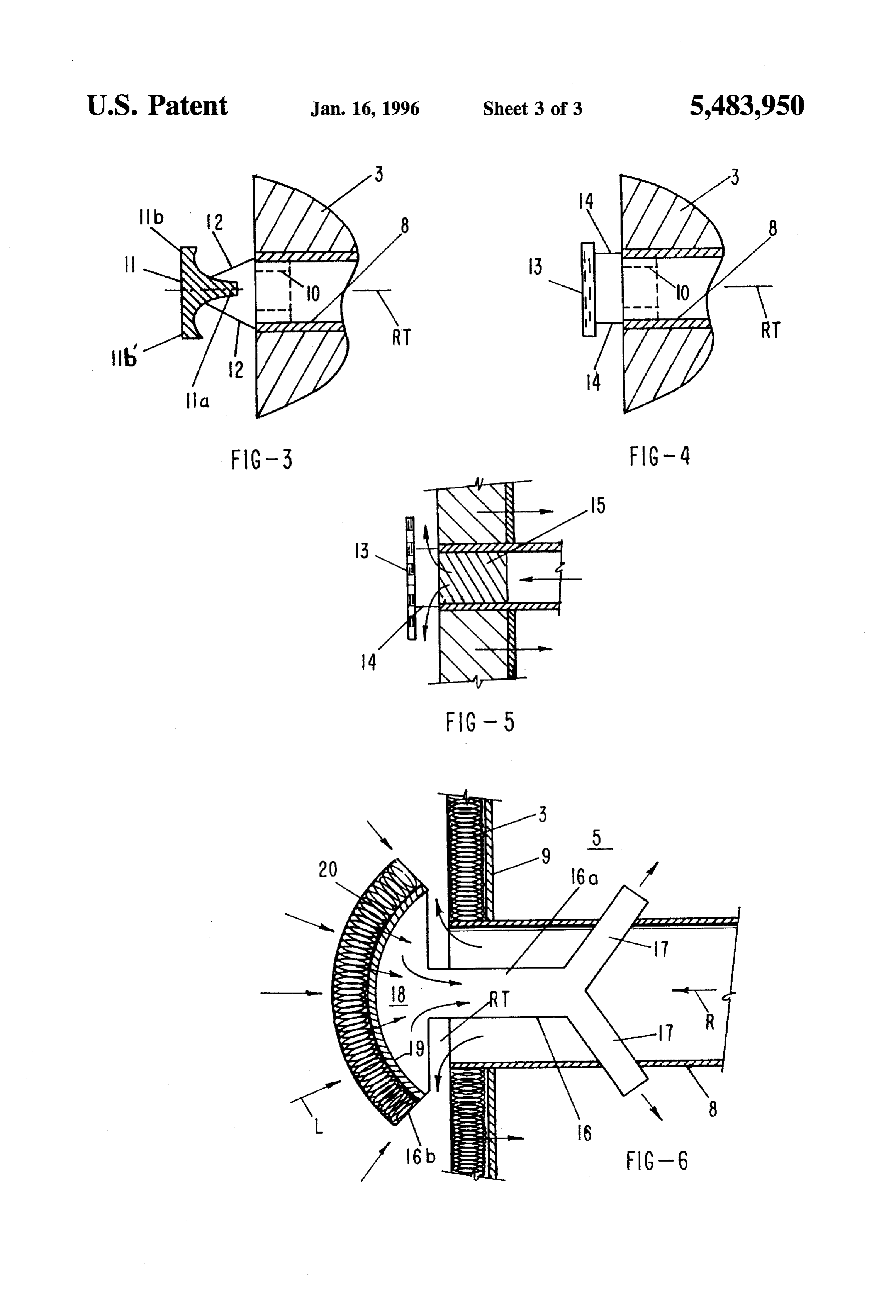
mined, preferably uniform, manner and each have coordi FIG.3 an enlarged partial representation of a return pipe nated therewith a return pipe extending to the upstream side with coordinated deflecting mushroom; of the absorber.
Then it is furthermore expedient that the outlet opening of FIG. 4 a representation comparable to FIG. 3 with a each returnpipe is provided with a deflection device. This is 40 deflecting plate;
preferably also the radiation protection device for the mouth FIG. 5 a representation comparable to FIG. 4 whereby an of the return pipe in case that the return pipe is not stable absorbent plug is inserted into the mouth of the return pipe; with respect to radiation. and
In a preferred manner the deflecting member is a deflect FIG. 6 a solar device with mushroom-shaped deflecting ing mushroom having a leg that is aligned with the center of 45 member that makes possible a higher utilization of radiation. the mouth of the return pipe. The mushroom may be of a massive (non-hollow, non-airpermeable) construction. How DESCRIPTION OF PREFERRED ever, it is also possible that the mushroom has a head with EMBODIMENTS an air-permeable absorbent material and the leg is hollow and connected with the chamber located at the downstream 50 According to FIG. 1, the air receiver 1 has a housing 2 side of the absorber. In this manner, on the one hand, the with an absorber 3 supported with supports4a, 4b connected mouth of the return pipe is protected against radiation, and, at one of its end faces. The absorber is heated by the incident on the other hand, an optimal use of the incident radiation is solar radiation S and which is penetrated by the sucked-in air achieved since the heated air above the mushroom head is stream L. Downstream of the absorber 3 a chamber 5 is introducible into the heated air stream downstream of the 55 provided from which the heated air H heated by the absorber downstream side of the absorber. may be sucked. The sucked heated air H is subjected to a A simple design of the deflecting member is provided heat exchange process, for example, in a non-represented when it is in the form of plate that is positioned at a distance steam generator, and at least a partial stream of the air that from the mouth of the return pipe. has not been completely cooled within the heat exchanger is The deflecting member may be made of a radiation 60 returned as return air R. The return air R is returned with a impermeable material, for example, aheat-resistant ceramic return air distributer 6 that is positioned at a distance from material, or a material that is at least partially radiation the absorber 3 within the housing 2. The return air distributer permeable, such as, for example, quartz glass. 6 is comprised of a central pipe 6a radially penetrating the When a radiation permeable deflecting member is used, it heated air collecting chamber 5 and a plurality of branch is expedient to provide a plug made of absorbent material in 65 pipes 6b that extend branch-like from the central pipe 6a the mouth of the returnpipe since in this manner the incident whereby the central pipe 6a and the branch pipes 6b are radiation at the cross-section of the mouth is also utilized. provided with bores 7 such that a substantially uniform
Page 7
distribution of bores 7 over the cross-section of the heated the radiation is collected by the absorbent material. The air air collecting chamber 5 is achieved. To each bore a return sucked through the head is heated and is guided via the pipe 8 is connected that first penetrates an aperture plate 9, branch pipes 17 into the heated air collecting chamber. coordinated with the downstream side 3b of the absorber, The present inventionis, of course, in no way restricted to and then extends through the absorber to the upstream side the specific disclosure of the specification and drawings, but 3a. The return air partial streams RT that exit from the return also encompasses any modifications within the scope of the pipes 8 are deflected at the upstream side 3a. appended claims.
The returnpipes 8 in FIG. 1 are represented with identical What we claim is:
diameters. When it is desired for a uniform distribution to 1. A solar device comprising:
provide different streams of volume to different locations of O an air receiver comprising a housing with a first and a the receiver, the pipes may have different diameters, whereby with respect to the radiation intensity profile in the second end and an air-permeable absorber connected central area of the upstream side 3a pipes of a greater within said housing at said first end, said absorber diameter and at the outer areas pipes of a smaller diameter heated by solar radiation;
may be used. It is also possible to insert nozzle inserts 10 15 said absorber having an upstream side and a downstream that have different bore widths into pipes of identical diam side, said housing having a heated air chamber down eters, is represented in a dashed line in FIGS. 3 and 4. stream of said absorber, with a stream of air guided When the return pipes 8 are rigidly connected with the through said absorber from said upstream side to said return air distributer that in itself is a rigid structure, the downstream side into said heated air chamber and return pipes 8 may be used as holding elements for the 20 thereby heated to generate heated air; absorber, especially when the absorber is designed in a said housing comprising a conduit means for removing known manner from individual absorber modules 3. said heated air from said heated air chamber for cooling In order to improve the deflection of the partial streams of to produce useful heat energy and cooled air; the return air R through the pipes 8 at the upstream side 3a, means for returning at least a portion of said cooled air as it is possible to provide at the mouth of the pipes a deflector 25 return air in a plurality of partial streams to said mushroom 11, as shown in FIG. 3, that is supported with absorber, said means for returning guiding said partial suitable stays 12 at the pipe. The leg 11a is coordinated with streams through said absorber counter to said stream of the mouth of the pipe 8. According to FIG.3, the head of the air without mixing therewith from said downstream mushroom 11b may be designed such that a 90 deflection side to said upstream side; and takes place or the head 11b' can be designed such that a 30 means for deflecting said partial streams at said upstream deflection of more than 90 occurs. (Both head designs are side such that said partial streams are deflected toward possible.) Due to the high surface load of the incident solar said upstream side.
energy, the mushroom is preferably manufactured from a 2. A solar device according to claim 1, wherein, when a highly heat resistant ceramic material. uniform distribution of said partial streams is present over With a suitable material selection the stays 12 or the 35 said upstream side, said return air is divided into partial holders 14 may serve as ribs for heat return since they are streams of different strength.
convectively cooled by the return air. 3. A solar device according to claim 1, wherein each of In the embodiment according to FIG. 4 the mouths of the said partial streams exiting from said absorber at said pipes 8 have coordinated therewith a transparent quartz plate 40 upstream side is forcibly deflected. 13 as the deflecting member that is connected to the pipe 8 4. A solar device according to claim 1, wherein: with holders 14. Since the plate 13 is transparent for the said means for returning includes a return air distributor radiation, it does not shade any area of the absorber. In this connected within said housing downstream of said case, the pipe must be made of a radiation-resistant material absorber in a flow direction of said heated air; such as ceramic, or at least the mouth of the returnpipe must 45 said return air distributor is spaced at a predetermined be protected by other means with forced cooling. distance from said absorber and has a radial extension It must be noted that the return pipes penetrating the that corresponds substantially to a radial extension of absorber do displace a part of the absorber volume relative an end face of said absorber facing said return air to the volume of the prior art absorbers; however, due to the distributor;
uniformness of the distribution of a return air an overall 50 said return air distributor comprising outlet openings efficiency improvement of the solar device is achieved. distributed in a predetermined manner about said return As is shown in FIG.5 it is possible, when using a radiation air distributor, permeable deflecting device 13, to reduce the aforemen said return air distributor further comprising for each said tioned displacement effect by providing a plug 15 made of outlet opening one return pipe, said return pipes con radiation absorbent material. 55 nected to said outlet openings and extending to said In FIG. 6 a mushroom-shaped deflecting member 16 is upstream side of said absorber, represented having a hollow leg 16a that engages the mouth 5. A solar device according to claim 4, wherein said of the return pipe 8 and that is in flow connection via two absorber is comprised of individual absorber modules and pipe sections 17, penetrating the wall of the returnpipe from wherein said return pipes serve as holding elements for said the inside to the outside, with the heated air collecting 60 absorber modules.
chamber 5. The hollow leg 16a is connected with a heated 6. A solar device according to claim 4, wherein for air collecting chamber 18 in the head 16b of the mushroom. adapting said partial stream to a solar radiation profile said The cover of the collecting chamber 18 is formed by a return pipes have different diameters. cup-shaped aperture plate 19that has connected to its outer 7. A solar device according to claim 4, wherein for side an absorbent material 20 that is comparable to the 65 adapting said partial stream to a solar radiation profile said absorber 3. With this arrangement the mouth of the return return pipes have identical diameters and comprise nozzle pipe 8 is protected against radiation, and, on the other, hand inserts of different bores.
Page 8
8. A solar device according to claim 4, wherein said return a chamber is positioned within said housing adjacent to air distributor is comprised of an air inlet pipe penetrating said downstream side of said absorber; said housing and extending radially within said housing and said mushroom-shaped deflecting member has a head and further comprised of transverse pipes extending perpendicu a leg;
larly from said air inlet pipe in a common radial plane to both sides of said air inlet pipe, wherein said outlet openings said head comprises an air-permeable absorbent material; are positioned at said inlet pipe and at said transverse pipes and in a predetermined distribution. said leg is hollow and connected to said chamber. 9. A solar device according to claim 4, wherein said outlet 15. A solar device according to claim 10, wherein said openings are substantially uniformly distributed. 10 10. A solar device according to claim 4, wherein said said mouth.member is a plate that is spaced at a distance from deflecting means of deflecting comprises a deflecting member for each 16. A solar device according to claim 10, wherein said said return pipe and wherein each said return pipe has a deflecting member consists of a radiation-impermeable mouth, said deflecting members positioned at said mouth of material.
said return pipes. 15 11. A solar device according to claim 10, wherein said 17. A solar device according to claim 10, wherein said deflecting member is a radiation protection device for said deflecting member consists of a material that is partially mouth of said return pipe. radiation-impermeable.
12. A solar device according to claim 10, wherein said 18. A solar device according to claim 10, wherein said deflecting member is mushroom-shaped and has a leg 20 deflecting member is radiation-permeable and wherein said extending toward a center of said mouth of said returnpipe. return pipe further comprises a plug inserted into said 13. A solar device according to claim 12, wherein said mouth, said plug consisting of a radiation absorbent mate mushroom-shaped deflecting member is of a massive con rial.
struction.
14. A solar device according to claim 12, wherein:
Provenance
- Collection
- Cited prior art
- Original PDF
- patentimages.storage.googleapis.com →
- Filed
- 1993-07-16
- Pages
- 8
- Method
- pdftotext (the PDF's own text layer) + pdftoppm 300dpi page scans
- Source
- Google Patents bibliographic record
- Granted
- 1996-01-16
- Inventors
- Gunter Keintzel; Manfred Schmitz-Goeb; Hans W. Fricker; L&C Steinmueller GmbH
- Transcribed from
- patentimages.storage.googleapis.com →