Figure (2-4)
Adjusting Flame Temperature
Also written Positive Probe Assembly
How it is written
- (2-4) 6×
Drawings 3
-
Gas Retarding Process, as illustrated in Figure (2-4) · Flame Temperature Adjustment
-
2-4 Positive Probe Assembly · Water Fuel Injector Illustrations
-
Beside the passage · Quenching Circuit
Where it is named · 6
Flame Temperature Adjustment 2×
-
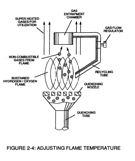
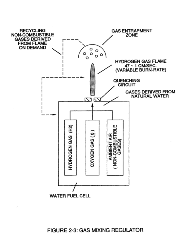
By capturing and recycling the expelled non-combustible gas (D) (derived from and supplied by the water bath) back into the sustained hydrogen gas-flame or Fuel-Cell causes the gas-flame temperature to be "changed" or "altered" by way of the Gas Retarding Process, as illustrated in Figure (2-4) as to Figure (2-3).
-
Gas Retarding Process, as illustrated in Figure (2-4)
Quenching Circuit 1×
Quenching Nozzle 1×
-
Additional Quenching Circuits arranged in a Disc-shape configuration forms a "Quenching Nozzle" when attached to an "Quenching Tube", as illustrated in Figure (2-4) as to Figure (2-6).
Catalytic Block Assembly 2×
-
... preventing Gas-Oxide formation, as illustrated in Figure (2-8) as to Figure (2-4).
-
Figure (2-4)