Figure (2-2)
Hydrogen Burn Rate
Also written Plug Housing
How it is written
- (2-2) 5×
Drawings 3
-
Captioned as this figure · Spark-Ignition Tube
-
2-2 Plug Housing · Water Fuel Injector Illustrations
-
Figure (2-3) · Flame Temperature Adjustment
Where it is named · 5
Spark-Ignition Tube 2×
-
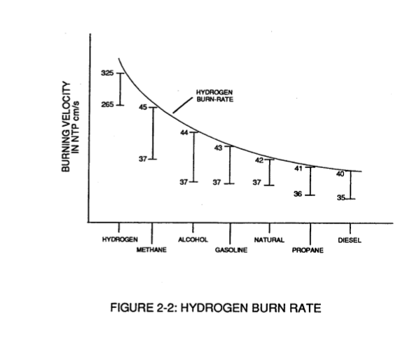
The expanding and moving Gas-Flame travels (away from spark-igniter) the linear length of the gas filled tube (C) and is "detected" and "measured" (length between spark-igniter and light-detector) in one second after gas-ignition. The Gas-Ignition Process, now, establishes the "Burn-Rate" of a Burnable Gas-Mixture in centimeters per second (cm/sec.), as illustrated in Figure (2-2).
-
Different types of "Burnable" Gas-Mixtures exposed to the Gas-Ignition Process were tested, measured, recorded and systematically arranged as to cm/sec. length, see vertical bar Graph (2-2) again.
Gas Injection Process 1×
-
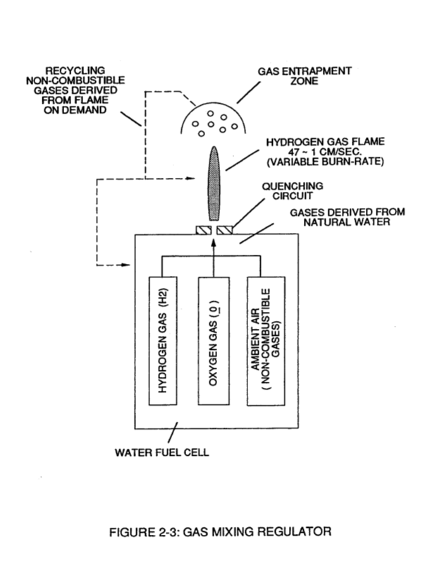
Progressive and controlled intermixing of the non-combustible gases (B/D) allowed the "Burn-Rate" of Hydrogen to be "lowered" or "adjusted" to "match" or ... co-equal the "Burn-Rate" of other Fuel-Gases, see curve line in Figure (2-2).
Flame Temperature Adjustment 1×
-
The recycling gases (D) controlled by an Gas Flow Regulator allows the gas flame-temperature to be "adjusted" or "calibrated" to any gas burning level (S), as so illustrated in Figure (2-2).
Internal Combustion Engine 1×
-
The Gas Combustion Stabilization Process (recycling non-combustible gases) is also applicable to operating an Internal Combustion Engine without changing Engine-Parts since the Gas Retarding Process allows the hydrogen "Burn-Rate to "equal" the "Burn-Rate" of Gasoline or Diesel-Fuel, as illustrated in Figure (2-2).