patent · US765078
Asynchronous motor.
12 July 1904
Page 1
Drawing sheet — no readable text.
Page 2
Drawing sheet — no readable text.
Page 3
No. 65,078. Patented July 12, 1904.
UNITED STATES PATENT OFFICE.
BAUI JIGOUZO, OF WANVES, FRANCE.
ASYNCHRONOUS MOTOR.
SPECIFICATION forming part of Letters Patent No. 765,078, dated July 12, 1904. Application filed December 1, 1902, Serial No, 133,427, (No model.)
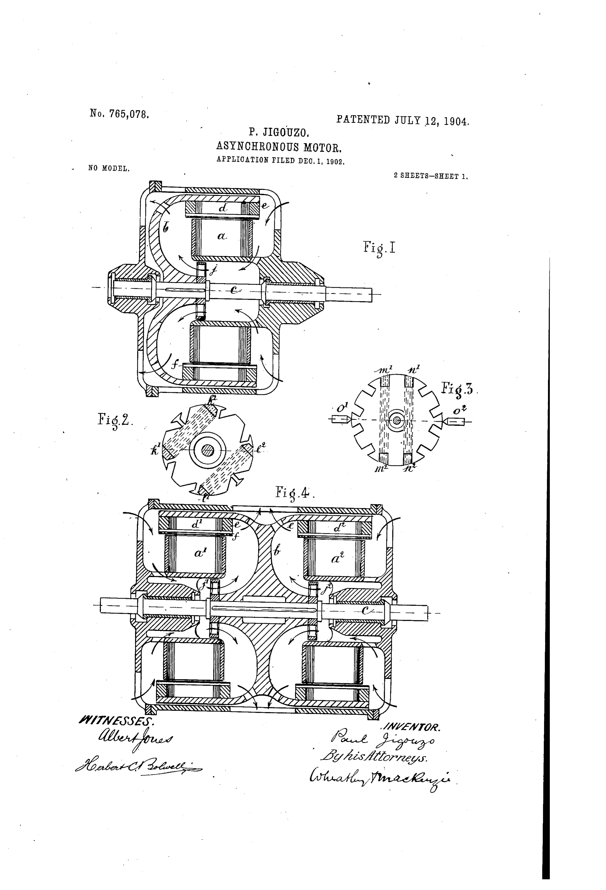
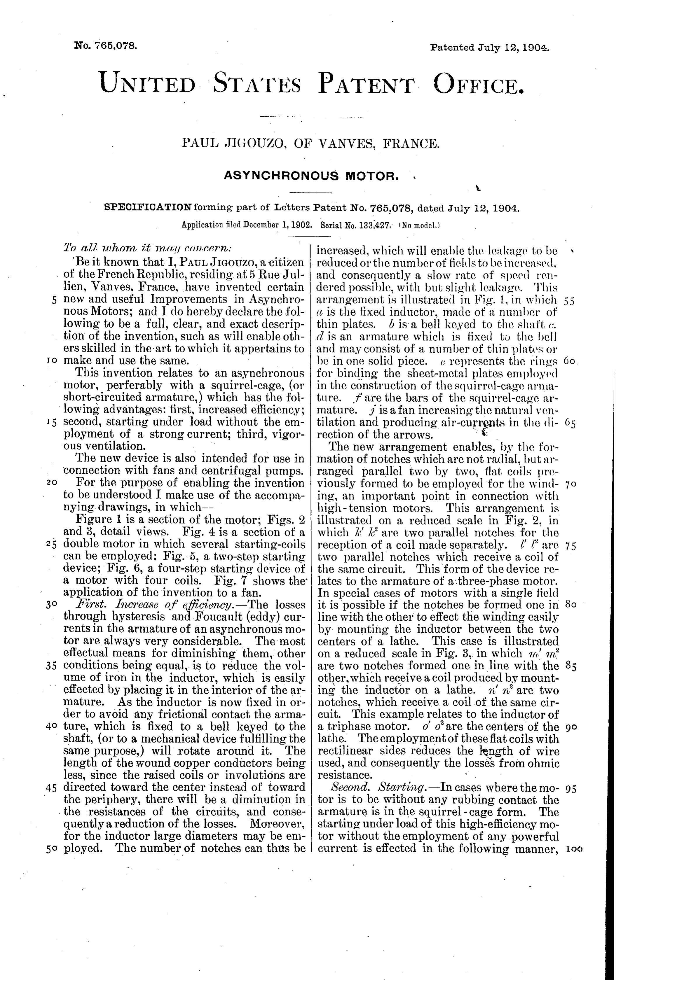
To all uhon, it inctly (oneern: increased, which will enable the leakage to be "Be it known that I, PAULJIGOUZo, a citizen reduced or the number of fields to be increased, of the French Republic, residing at 5 Rue Jul and consequently a slow rate of speed ren lien, Vanves, France, have invented certain dered possible, with but slight leakage. This new and useful Improvements in Asynchro arrangement is illustrated in Fig. 1, in which 55 nous Motors; and I do hereby declare the fol (, is the fixed inductor, made of a number of lowing to be a full, clear, and exact descrip thin plates. d is a bell keyed to the shaft, c. tion of the invention, such as will enable oth d is an armature which is fixed to the bell ers skilled in the art to which it appertains to and may consist of a number of thin plates or d make and use the same. be in one solid piece. e represents the rings This invention relates to an asynchronous for binding the sheet-metal plates employed motor, perferably with a squirrel-cage, (or in the construction of the squirrel-cage arma short-circuited armature,) which has the fol ture. f are the bars of the squirrel-cage ar lowing advantages: first, increased efficiency; mature. f is a fan increasing the natural ven 15 second, starting under load without the em tilation and producing air-currents in the di ployment of a strong current; third, vigor rection of the arrows. is ous ventilation. The new arrangement enables, by the for The new device is also intended for use in mation of notches which are not radial, but ar connection with fans and centrifugal pumps. ranged parallel two by two, flat coils pre 2O For the purpose of enabling the invention viously formed to be employed for the wind to be understood I make use of the accompa ing, an important point in connection with nying drawings, in which-- high-tension motors. This arrangement is Figure 1 is a section of the motor: Figs. 2 illustrated on a reduced scale in Fig. 2, in and 3, detail views. Fig. 4 is a section of a which k' K' are two parallel notches for the 25 double motor in which several starting-coils reception of a coil made separately. l l are 75 can be employed: Fig. 5, a two-step starting two parallel notches which receive a coil of device; Fig. 6, a four-step starting device of the same circuit. This form of the device re a motor with four coils. Fig. 7 shows the lates to the armature of a three-phase motor. application of the invention to a fan. In special cases of motors with a single field so First. Increase of efficiency.-The losses it is possible if the notches be formed one in through hysteresis and Foucault (eddy) cur line with the other to effect the winding easily rents in the armature of an asynchronous mo by mounting the inductor between the two tor are always very considerable. The most centers of a lathe. This case is illustrated effectual means for diminishing them, other on a reduced scale in Fig. 3, in which no an 35 conditions being equal, is to reduce the vol are two notches formed one in line with the ume of iron in the inductor, which is easily other, which receive a coil produced by mount effected by placing it in the interior of the ar ing the inductor on a lathe. n n are two mature. As the inductor is now fixed in or notches, which receive a coil of the same cir der to avoid any frictional contact the arma cuit. This example relates to the inductor of 4O ture, which is fixed to a bell keyed to the a triphase motor. O'o' are the centers of the go shaft, (or to a mechanical device fulfilling the lathe. The employment of these flat coils with same purpose,) will rotate around it. The rectilinear sides reduces the kength of wire length of the wound copper conductors being used, and consequently the losses from ohmic less, since the raised coils or involutions are resistance. • 45 directed toward the center instead of toward Second. Starting.-In cases where the mo 95 the periphery, there will be a diminution in tor is to be without any rubbing contact the the resistances of the circuits, and conse armature is in the squirrel-cage form. The quently a reduction of the losses. Moreover, starting under load of this high-efficiency mo for the inductor large diameters may be em tor without the employment of any powerful o ployed. The number of notches can thus be current is effected in the following manner,
Page 4
Ventilation.-In asynchronous motors as
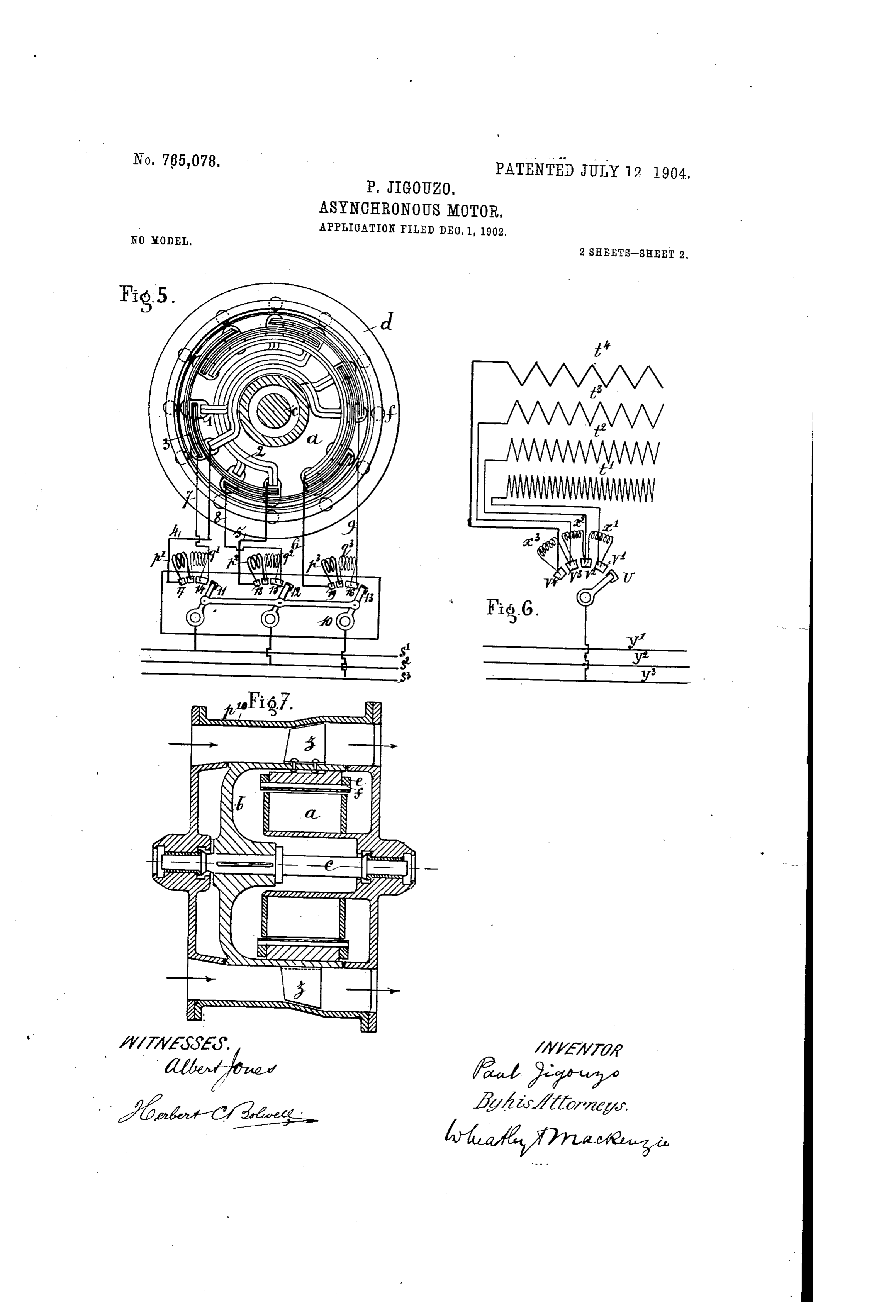
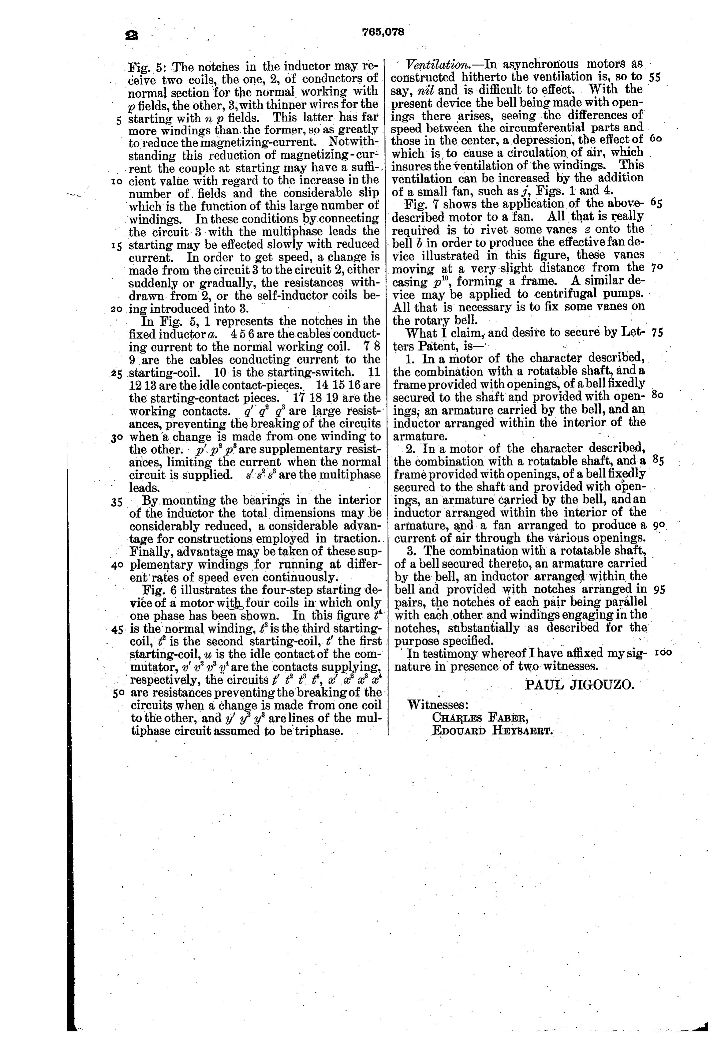
Fig. 5: The notches in the inductor may re constructed ceive two coils, the one, 2, of conductors of hitherto the ventilation is, so to 55 normal section for the normal working with say, nil and is difficult to effect. With the pfields, the other, 3, with thinner wires for the present device the bell being made with open starting with n p fields. This latter has far ings there arises, seeing the differences of more windings than the former, so as greatly. speed between the circumferential parts and to reduce the magnetizing-current. Notwith those in the center, a depression, the effect of standing this reduction of magnetizing- cur which is, to cause a circulation of air, which rent the couple at starting may have a sufi-, insures the ventilation of the windings. This O cient value with regard to the increase in the ventilation can be increased by the addition number of fields and the considerable slip of a small fan, such as , Figs. 1 and 4. which is the function of this large number of Fig. 7 shows the application of the above windings. In these conditions by connecting described motor to a fan. All that is really the circuit 3 with the multiphase leads the required is to rivet some vanes 2 onto the starting may be effected slowly with reduced bell b in order to produce the effectivefan de current. In order to get speed, a change is vice illustrated in this figure, these vanes made from the circuit 3 to the circuit 2, either moving at a very slight distance from the suddenly or gradually, the resistances with casing p", forming a frame. A similar de drawn from 2, or the self-inductor coils be vice may be applied to centrifugal pumps. All that is necessary is to fix some vanes on 20 ing introduced into 3.
In Fig. 5, 1 represents the notches in the the rotary bell.
fixed inductora. 456 are the cables conduct What I claim, and desire to secure by Let 75 ing current to the normal working coil. 78 ters Patent, is-': - 9 are the cables conducting current to the 1. In a motor of the character described, starting-coil. 10 is the starting-switch. 11 the combination with a rotatable shaft, and a 1213 are the idle contact-pieces. 14 1516 are frame provided with openings, of abellfixedly the starting-contact pieces. 17 1819 are the secured to the shaft and provided with open working contacts. g' g g are large resist ings; an armature carried by the bell, and an ances, preventing the breaking of the circuits inductor arranged within the interior of the when a change is made from one winding to armature. . . .. the other. p' p' p'are supplementary resist 2. In a motor of the character described, ances, limiting the current when the normal the combination with a rotatable shaft, and a circuit is supplied. s'ss' are the multiphase frame provided with openings, of a bellfixedly leads, . .. " secured to the shaft and provided with open 35 By mounting the bearings in the interior ings, an armature carried by the bell, and an of the inductor the total dimensions may be inductor arranged within the interior of the considerably reduced, a considerable advan armature, and a fan arranged to produce a go tage for constructions employed in traction. current of air through the various openings. Finally, advantage may be taken of these sup 3. The combination with a rotatable shaft, plementary windings for running at differ of a bell secured thereto, an armature carried entrates of speed even continuously. . by the bell, an inductor arranged within the Fig. 6 illustrates the four-step starting de bell and provided with notches arranged in 95 vice of a motor with four coils in which only pairs, the notches of each pair being parallel one phase has been shown. In this figure t' with each other and windings engaging in the is the normal winding, tis the third starting notches, stubstantially as described for th coil, t” is the second starting-coil, t' the first purpose specified. . starting-coil, u is the idle contact of the com In testimony, whereofI have affixed my sig- Ioo mutator, ' ' ' are the contacts supplying, nature in presence of two witnesses. respectively, the circuits t t t it, a' aa'a' are resistances preventing the breaking of the - PAUL JIGOUZO. circuits when a change is made from one coil Witnesses: . to the other, and y' y' yarelines of the mul CHARLES FABER, tiphase circuit assumed to be triphase. EDOUARD HEYsAERT.
Provenance
- Collection
- Cited prior art
- Original PDF
- patentimages.storage.googleapis.com →
- Filed
- 1902-12-01
- Pages
- 4
- Method
- pdftotext (the PDF's own text layer) + pdftoppm 300dpi page scans
- Source
- Google Patents bibliographic record
- Granted
- 1904-07-12
- Inventors
- Paul Jigouzo
- Transcribed from
- patentimages.storage.googleapis.com →