patent · US3997108
Automatic air flow control
14 December 1976
Page 1 — bibliographic record
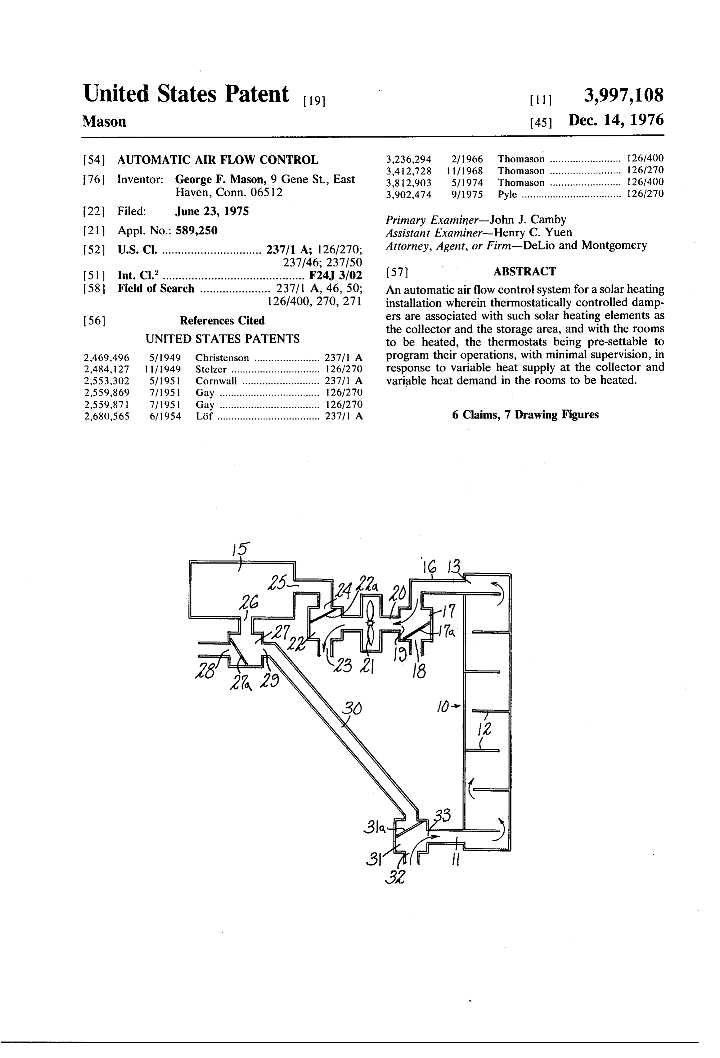
United States Patent to 11, 3,997,108 Mason 45 Dec. 14, 1976 54 AUTOMATIC AIR FLOW CONTROL 3,236,294 2/1966 Thomason ......................... 126/400 3,412,728 l l 1968 Thomason ......................... 126/270 76 Inventor: George F. Mason, 9 Gene St., East 3,812,903 5/1974 Thomason ......................... 26/400 Haven, Conn. 06512 3,902,474 9/1975 Pyle ................................... 126/270
Primary Examiner-John J. Camby (21) Appl. No.: 589,250 Assistant Examiner-Henry C. Yuen 52 U.S. Cl. ............................... 237/1 A; 126/270; Attorney, Agent, or Firm-DeLio and Montgomery
51 int. Cl'............................................ F24, 3/02 58 Field of Search ...................... 237/1 A, 46, 50: An automatic airflow control system for a solar heating 126/400, 270, 271 installation wherein thermostatically controlled damp 56) References Cited ers are associated with such solar heating elements as
UNITED STATES PATENTS
the collector and the storage area, and with the rooms to be heated, the thermostats being pre-settable to 2,469,496 5/1949 Christenson ....................... 23711 A program their operations, with minimal supervision, in 2,484, 127 l l fl949 Stelzer ............................... 126/270 response to variable heat supply at the collector and 2,553,302 5/1951 Cornwall ........................... 23711 A variable heat demand in the rooms to be heated. 2,559,869 7/1951 Gay ................................... 126/270 2,559,871 7/1951 Gay ................................... 126/270 2,680,565 6/1954 Löf .................................... 237/1 A 6 Claims, 7 Drawing Figures
Page 2
Drawing sheet — no readable text.
Page 3
Drawing sheet — no readable text.
Page 4
several parts whereby the above named and other ob
AUTOMATIC AIR FLOW CONTROL jects may effectively be attained.
The invention accordingly comprises the features of
This invention relates to an automatic air flow con construction, combination of elements, and arrange trol system for a solar heating installation wherein ther ment of parts which will be exemplified in the construc mostatically controlled dampers are associated with tion hereinafter set forth, and the scope of the inven such solar heating elements as the collector and the tion will be indicated in the claims.
storage area, and with the rooms to be heated, the A practical embodiment of the invention is shown in thermostats being pre-settable to program their opera the accompanying drawings, wherein:
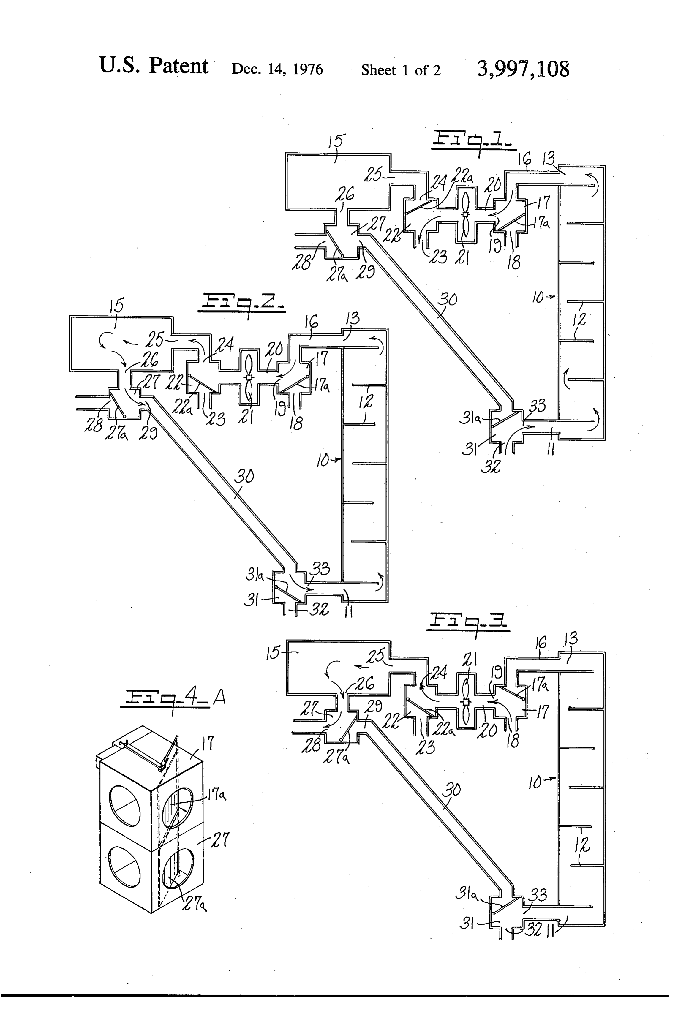
tions, with minimal supervision, in response to variable 10 FIG. 1 is a diagrammatic representation of the ele heat supply at the collector and variable heat demand ments of a solar heating system, and their inter-rela in the rooms to be heated. tion, with dampers set to circulate warm air from the The essential elements of a simple solar heating in collector through the house;
stallation comprise a collector, for receiving the sun's FIG. 2 is a similar diagrammatic representation with rays and transmitting their heat to a fluid such as air, a 5 the dampers set to circulate warm air from the collec storage bin containing heatable materials to which the tor to storage;
fluid can deliver any heat which is not used for heating FIG. 3 is a similar diagrammatic representation with the rooms of a house, ducts for conveying the heat the dampers set to circulate warm air from storage to transfer fluid along a desired course between the col the house;
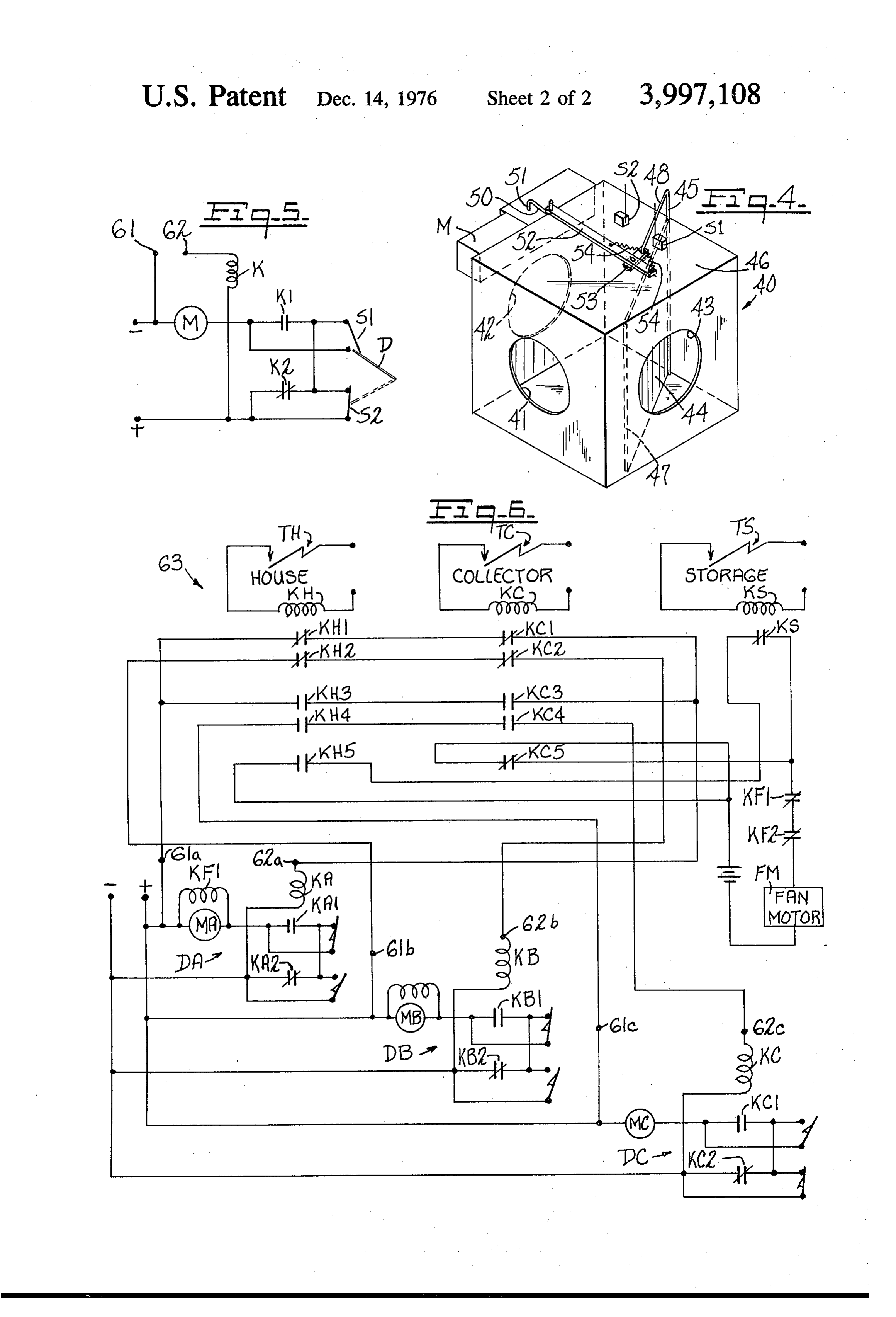
lector, storage bin and rooms, one or more fans to drive 20 FIG. 4 is a somewhat diagrammatic isometric projec and/or draw the fluid along its course and one or more tion of a suitable form of damper for controlling the air dampers or the like, adjustable to positions which will flow;
direct the fluid along the particular course which ma FIG. 4A is a view like FIG. 4, showing the stacking of be suitable or desired at any given moment. one damper on another,
The most basic element is the collector which picks 25 FIG. 5 is a diagram of the damper circuit; and up thermal energy from the sun's rays and heats the F.G. 6 is a circuit diagram showing the pertinent transfer fluid for use as needed. The collector is also elements for controlling automatically the operation of the most unpredictable element, since it depends on the system.
exposure to the sun which can take place (effectively) Since the specific details of air circulation within a during only about 10 hours of any day, and is subject to 30 house, to and from one or more rooms thereof, will interruptions at any time, depending on weather condi vary according to the size and design of each individual tions, and is also subject to variations in the intensity of house, FIGS. 1, 2 and 3 show only ducts which supply the solar radiation. The number of hours of darkness at air to a house and receive air from a house, regardless any given season can, of course, be calculated, and of any additional ducting in the house. The location of ideal operation of a solar heating system would include 35 the heating system elements will be indicated below. the collection and storage of enough thermal energy, Referring to the drawings, the system includes a solar during the sunny hours, to heat the house adequately heat collector 10, of any effective type, designed to during the dark hours. Since it is normally impossible to receive solar thermal energy and to transfer it to an air anticipate ideal conditions over any given period of stream which may be circulated through the collector. time, a system should have excess collecting capacity 40 As shown, the collector has an inlet end 11, a series of and excess storage capacity, if auxiliary heating is not baffles 12 causing the air to follow a serpentine path, to be relied on. It is also desirable to provide the instal and an outlet end 13. The dimensions and shape of the lation with an automatically operating air flow control collector may vary widely but it will normally include system, such that changing conditions of heat supply one or more flat black surfaces (plastic or painted and demand can be responded to promptly, for opti 45 metal) for solar heat absorption and one or more air mum utilization of the available thermal energy. passages adjacent to said surfaces. It must, obviously, It is therefore an object of the present invention to be placed in a location where its heat absorbing area is provide flow control means which, when properly set, exposed to direct sunlight for as many hours a day as will respond automatically to such combinations of possible, and at the most favorable average angle or conditions, and changes thereof in any normal se 50 angles. Any exposed adjacent ducting may also be quence, as the following: made of black material to supplement the heat absorp Collector operating, house needs and receives heat. tion in the collector.
Collector operating, house warm enough, heat to A storage unit is essential if the system is to be opera storage. tive at times when the sun is not shining on the collec Collector not operating, house needs and receives 55 tor, as at night or on a cloudy day. In one type of stor heat from storage. age unit a well insulated bin is provided with an array of Collector not operating, house needs heat, storage water-filled plastic bottles (e.g., 1000 1-gallon bottles) cool. suitably disposed to permit air circulation and heat It is a further object to provide an improved damper exchange. In another type the bin is filled with a quan unit which may be standardized for installation at any 60 tity of rocks of graduated sizes, supported and distrib required point in the system, whereby the dampers are uted in such a manner that air can be passed through interchangeable and a supplier needs to stock only a the mass. A rock-filled storage unit can be structurally single model. associated with the collector or can be located else It is another object to provide improved circuitry for where, as in the basement or more or less buried; wher the system, with the simplest possible elements, readily 65 ever located it has the advantage, over water bottles, available for servicing as needed. that it can never be frozen in cold weather. The storage It is a still further object to provide certain improve unit 15, shown herein, may be of any suitable type, but ments in the form, construction and arrangement of the the rock type is preferred.
Page 5
In the air circulation path shown, the collector outlet house) and opens outlet 29 so that air from storage can 13 is connected by a duct 16 to a first damper 17, 17a pass through the duct 30, and damper vane 31a closes having an alternative inlet 18 from the house and an the inlet 32 (from the house) to permit air to pass outlet 19 to a duct 20 containing a fan 21. From the fan through outlet 33 for recirculation through the collec the air path goes to a second damper 22, 22a having an tor. The controls are set to maintain this storage cycle outlet 23 to the house and an outlet 24 to the inlet 25 as long as the collector is warmer than the storage bin; of the storage unit 15. The storage outlet 26 connects since the air which is recirculated through the collector with a third damper 27, 27a having an outlet 28 to the may be somewhat warm as it comes from storage, the house and an outlet 29, connected by the duct 30 to a air passing to storage can, under good collecting condi fourth damper 31, 31a which has an inlet 32 from the 10 tions, become relatively super-heated and correspond house and outlet 33 to the inlet end 11 of the collector. ingly large amounts of thermal energy can be stored for The same parts are shown in each of FIGS. 1, 2 and future use. When the collector ceases to be effective, as 3, with dampers adjusted to positions appropriate for due to clouds or darkness, all circulation is stopped by the respective principal modes of operation, as will be turning off the fan.
explained below. 15 If the house calls for heat when the collector is un A suitable damper construction is shown in FIG. 4 able to supply it, the circulation path shown in FIG. 3 is wherein the housing 40 is in the form of a rectangular set up. Here, the damper vane 17a is turned to close the box having a vent opening 41 in one end wall, vent inlet from the collector and open the inlet 18 from the openings 42, 43 in two side walls and a vane or flap 44 house; the fan draws cool air in from the house and fixed to a vertical axle 45 pivotally mounted adjacent passes it through damper 22, outlet 24 and inlet 25 to the end wall 46. The vane or flap 44 is of a size to swing the storage bin 16; from storage, where the air is freely with minimum clearance between the bottom warmed, it goes to damper 27 and through outlet 28 to and top walls and its free edge may desirably be pro the house, damper vane 27a being switched to cut off vided with a resilient sealing strip 47 such as a rubber the duct 30.
“weather strip' to seal tightly against each side wall 25 Since heat is supplied normally either by the collec and to muffle the sound of coming in contact with the tor (FIG. 1) or by the storage bin (FIG. 3), never both respective wall. A lever arm 48 is fixed to the upper end at once, the damper vanes 17a and 27a will always of the axle 45 and extends across the top of the damper, move in unison. The dampers 17 and 27 may, if de parallel to the vane or flap, between upwardly project sired, be combined in a single unit, one damper above ing limit switches S1, S2. Actuation of the vane or flap 30 the other as indicated in FIG. 4A, with the respective is effected by a small motor M driving gears (not vanes or flaps on a single axle.
shown) to rotate a crank 50 on the gear shaft 51. The The damper vanes are positioned through a motor crank is connected to the lever arm 48 by a long link 52 control. A separate control is provided for each of and, preferably, a short link 53 which is centered by dampers 22 and 31, while damper vanes 17a and 27a springs 54, the effect of which is to permit closing of 35 are shown as being operated together. the damper vane or flap against either side wall with a A typical control circuit for a damper is shown in yielding contact or squeezing action, whereby precise FIG. 5 and comprises a damper motor M, a relay K adjustment of the throw of the crank 50 is not required. having controlled contacts K1 and K2 and limit In FIGS. 1, 2 and 3, the air circulation paths are switches S1 and S2. Rely K will be energized when a indicated by arrows and flow lines. 40 circuit is closed between terminals 61 and 62. The limit The condition illustrated in FIG. 1 is that wherein the switches are normally closed, but are opened by collector 10 is receiving thermal energy, by exposure to contact by the damper arm D (48 in FIG. 4). As shown the rays of the sun, and is therefore capable of collect in FIG. 5, the motor M is not energized since both ing heat either for use or for storage. The house is cool switch S1 and contact K1 are open. If relay K should be enough so that its thermostat TH calls for heat. In re 45 energized, contact K1 is picked up and contact K2 is sponse to this call, the damper vane 17a opens the dropped out. This circuit arrangement provides a cir passage through ducts 16 and 20 to the fan 21, the cuit through motor M by way of switch S2 and picked damper vane 22a closes the outlet 24 (to storage) and up contact K1. Motor M will then operate to drive opens the outlet 23 to the house, and the damper vane damper arm D to the opposite position. When the 31a opens the return passage between inlet 32 from the 50 damper arm opens the switch, the circuit to motor M is house through outlet 33 to the inlet end 11 of the col opened and movement of the damper is halted. The lector. Cool air from the house is drawn in through inlet circuit will remain in this condition and the damper 32, passed through the collector and returned to the arm in the position holding S2 open until relay K is house as warm air through the outlet 23, this circula de-energized. When this occurs, the contacts return to tion continuing until the house thermostat TH stops 55 the position shown in FIG. 5 and another circuit is calling for heat (or the collector thermostat TC indi established to motor M through contact K2 and switch cates that no more is available from the collector). S1. The motor will then operate until the damper arm At the completion of the house heating cycle, just D returns to the position shown, to open switch S1 described, and assuming that the sun is still shining on breaking the circuit to motor M. the collector, the control circuit (described below) 60 In the embodiment of the invention shown, three shifts the dampers to the condition illustrated in FIG.2 damper controls DA, DB, and DC are utilized and are where heat is being stored in the storage bin 15. The shown in FIG. 6. The damper controls DA, DB, and DC damper vane 17a is in the same position as before, are identical to the circuit shown in FIG. 5, except that opening the passage from the collector to the fan, but controls DA and DB include fan control relays KF1 and damper vane 22a is switched to close the outlet 23, 65 KF2. The relays KA, KB and KC are energized or de leading directly to the house, and to open the outlet 24, energized in response to the condition of a controller so that the air passes through duct 25 to the storage bin circuit 63 which is further responsive to the settings of 15. The damper vane 27a closes the outlet 28 (to the thermostats TH, TC and TS. Thermostat TH senses the
Page 6
temperature of the house, and is normally open if the each of the elements, house (space to be heated), col house is up to a predetermined temperature. If thermo lector and storage unit.
stat TH closes, it energizes a relay KH. Thermostat TC Other advantages of the system include the fact that senses the temperature in the collector and is open its power consumption is low and all elements could be when the collector is above a predetermined tempera operated on a 12 volt battery if necessary or preferred. ture. If relay TC should close, it energizes a relay KC. The collector and storage may be adjacent or sepa Thermostat TS senses the temperature in storage and if rated, as desired. The system is designed to make effi the temperature falls below a predetermined value it cient use of all available heat, by collection and storage will energize the relay KS. t of thermal energy whenever the collector is function Relay KH controls a plurality of contacts KH1-KH5. 10 Ing.
Relay KC controls contacts KC1-KC5. Relay KS has The relay coils can be equipped, in a conventional one control contact KS1 in circuit with fan motor FM. manner, with indicator lights to show the status of all The fan motor FM may be energized through normally elements, i.e., whether or not the collector is function closed contact KCS, or through normally opened 1ng.
contact KH5 when contact KS1 is closed. 15 The system is so designed that a minimum installation If all thermostats are open, the circuit is as shown in of collector, storage unit and one automatic damper FIG. 6 and the air flow circuit is as shown in FIG. 2. could be used initially, with other dampers added sub Damper control DA controls the position of arm 22a of sequently, in order to spread the expense. damper 22. Damper control DB controls the position of It may thus be seen that the objects of the invention arm 31a of damper 31 and damper control DC controls 20 set forth as well as those made apparent from the pre the position of arms 17a and 27a of dampers 17 and 27 ceding description are efficiently attained and, since respectively. Relays KA and KB are energized and certain changes may be made in the above construction relay KC is not energized, as shown in FIG. 6. without departing from the spirit and scope of the in Assume now that thermostat TH senses cooling of vention, it is intended that all matter contained in the the house and closes. Relay KH is energized and re 25 above description or shown in the accompanying draw verses its contacts from that shown in FIG. 6. When ings shall be interpreted as illustrative and not in a contacts KH1 and KH2 drop out, relays KA and KB are limiting sense.
de-energized. The motors MA and MB are then placed What I claim is:
in circuit and drive dampers 22a and 31a to the posi 1. A solar heating system comprising a collector hav tion shown in FIG. 1. At this point, storage 15 is out of 30 ing an inlet end and an outlet end, a heat storage unit the air flow circuit and air flows through opening 32 having an inlet end and an outlet end, a space to be over the collector and to the house through opening 23. heated, air ducts interconnecting in series in a closed During the time that the motor is operating to change system said collector and storage unit and air ducts the dampers, relays KF1 and KF2 are energized, drop connecting parts of said system to said space, a fan ping out their normally controlled contacts KF1 and 35 operatively associated with said first named ducts KF2 in the fan motor circuit to temporarily halt opera downstream of the collector, a plurality of dampers in tion of fan 21. series in said system each adjustable to alternative posi Assume that after a period of time the temperature in tions for establishing a desired air flow circuit, and an the collector falls, which is sensed by a thermostat TC electrical operating circuit for controlling automati and relay KC is energized. At this time the house ther 40 cally the adjustment of the dampers and operation of mostat TH is still calling for heat. Contact KC3 closes the fan, a first damper being located between the outlet and a circuit is closed between terminals 61a and 62a end of the collector and inlet end of the storage unit of relay KA, thus energizing relay K.A. Motor MA will and being adjustable to connect the outlet end of the be energized to drive damper 22a to the position shown collector alternatively to the inlet end of the storage in FIG. 3. Relay KC is energized when contact KC4 45 unit or to the space to be heated, a second damper closes, thus creating a circuit. through motor MC, being located between the outlet end of the storage unit which drives the dampers 17a and 27a to the position and inlet end of the collector and being adjustable to shown in FIG. 3. The fan is temporarily interrupted connect the inlet end of the collector alternatively to during change of position of the dampers as previously the storage unit or to the space to be heated, third and described and the house is heated by air drawn through 50 fourth dampers being located at opposite ends of the opening 18 by fan 21 into storage 15 and back into the storage unit and adjustable to connect both ends of the house through opening 28 in damper 27. storage unit with the space to be heated, the electrical If the temperature in storage now falls below a prede circuit including thermostats, in the collector, storage termined value, thermostat TS will close, relay KS will unit and space to be heated, and said electrical circuit be energized and operation of the fan will cease. The 55 being adapted to actuate dampers and the fan to cause system will then be inoperative until the collector tem warm air to be supplied to said space on demand of the perature rises to a predetermined value at which time thermostat therein when either other thermostat indi thermostat TC will open, de-energizing relay KC. cates that warm air is available from the collector or When contact KC opens, relay KC is de-energized, and from the storage unit.
motor MC is energized to drive dampers 17a and 27a to 60 2. A solar heating system according to claim 1 the position shown in FIG. 1. wherein the collector thermostat is adapted to cause The fan circuit is closed through contact KC5. Since elimination of the collector from the air flow circuit contact KH2 is open, there will be no change in state of upon drop of temperature in the collector. relay KB and the air flow circuit will return to that 3. A solar heating system according to claim 2 shown in FIG. 1. 65 wherein the storage thermostat is adapted to maintain In the foregoing manner the dampers are automati the storage unit in the air flow circuit as long as the cally controlled to place the system in a condition de storage temperature is sufficiently high and the space termined by the need for, and availability of heat in thermostat demands heat.
Page 7
4. A solar heating system according to claim 1 wherein the electrical circuit includes means for stop wherein the electrical circuit is adapted to actuate ping the fan while dampers are being moved. dampers and the fan to cause warm air to be supplied to 6. A solar heating system according to claim 1 the storage unit by the collector when the space ther- wherein each damper has a position in which an air mostat does not demand heat and the collector temper- 5 passage is opened through the damper to the space to ature is sufficiently high. be heated.
5. A solar heating system according to claim 1 ck k is k. k.
Provenance
- Collection
- Cited prior art
- Original PDF
- patentimages.storage.googleapis.com →
- Filed
- 1975-06-23
- Pages
- 7
- Method
- pdftotext (the PDF's own text layer) + pdftoppm 300dpi page scans
- Source
- Google Patents bibliographic record
- Granted
- 1976-12-14
- Inventors
- George F. Mason
- Transcribed from
- patentimages.storage.googleapis.com →