patent · US4160711
Assembly of electrodes
10 July 1979
Page 1 — bibliographic record
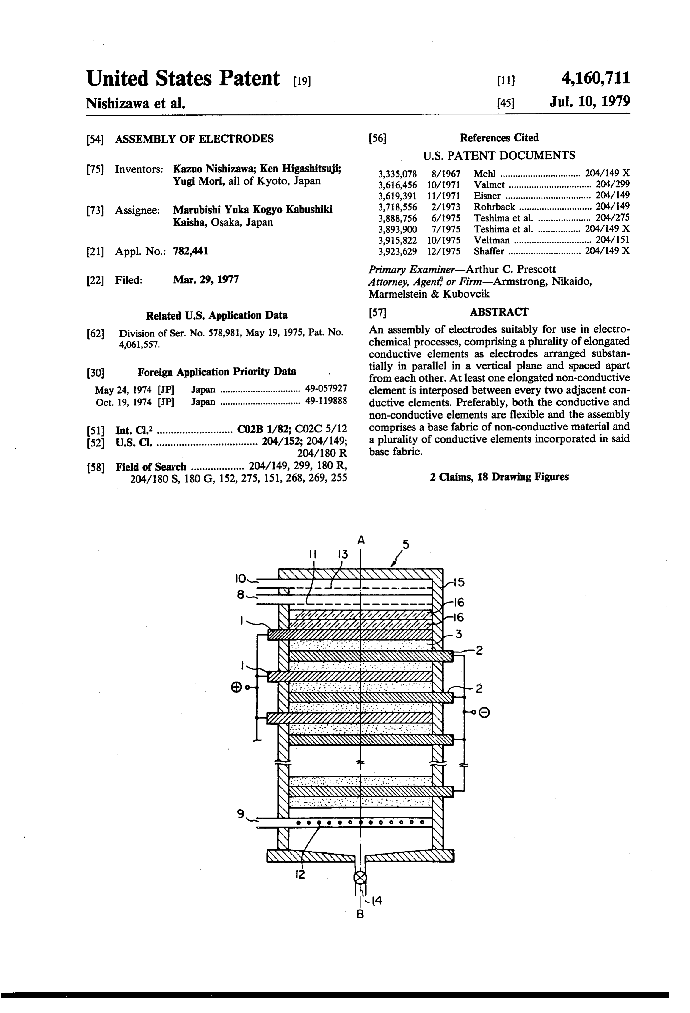
United States Patent (19) 11) 4,160,711 Nishizawa et al. (45) Jul. 10, 1979 (54) ASSEMBLY OF ELECTRODES (56) References Cited
75 Inventors: Kazuo Nishizawa; Ken Higashitsuji; 3,335,078 8/1967 Mehl ................................ 204/149 X Yugi Mori, all of Kyoto, Japan 3,616,456 10/1971 Valmet ................................. 204/299 3,619,391 11/1971 Eisner .................................. 204/149 (73) Assignee: Marubishi Yuka Kogyo Kabushiki 3,718,556 2/1973 Rohrback ............................. 204/149 Kaisha, Osaka, Japan 3,888,756 6/1975 Teshima et al. 204/275 3,893,900 7/1975 Teshima et al. 04/149 X 3,915,822 10/1975 Veltman .... ... 204/151 (21) Appl. No.: 782,441 3,923,629 12/1975 Shaffer ............................. 204/149 X Primary Examiner-Arthur C. Prescott 22 Filed: Mar. 29, 1977 Attorney, Agent or Firm-Armstrong, Nikaido, Marmelstein & Kubovcik
Related U.S. Application Data 57 ABSTRACT (62) Division of Ser. No. 578,981, May 19, 1975, Pat. No. An assembly of electrodes suitably for use in electro 4,061,557. chemical processes, comprising a plurality of elongated conductive elements as electrodes arranged substan (30) Foreign Application Priority Data tially in parallel in a vertical plane and spaced apart from each other. At least one elongated non-conductive
May 24, 1974 JP Japan ................................ 49-0.57927 element is interposed between every two adjacent con Oct. 19, 1974 JP Japan ................................ 49-19888 ductive elements. Preferably, both the conductive and non-conductive elements are flexible and the assembly 51) Int. C.’........................... CO2B 1/82; CO2C5/12 comprises a base fabric of non-conductive material and 52 U.S. C. .................................... 204/152; 204/149; a plurality of conductive elements incorporated in said
204/180 S, 180 G, 152, 275, 151,268,269,255 2 Claims, 18 Drawing Figures
NNXNN
NZZZZZ
n NNN
NNNNS
Page 2
Drawing sheet — no readable text.
Page 3
Drawing sheet — no readable text.
Page 4
Drawing sheet — no readable text.
Page 5
Drawing sheet — no readable text.
Page 6
Drawing sheet — no readable text.
Page 7
Drawing sheet — no readable text.
Page 8
Drawing sheet — no readable text.
Page 9
Drawing sheet — no readable text.
Page 10
Drawing sheet — no readable text.
Page 11
gaged. However, products formed on or in the vicinity
ASSEMBLY OF ELECTRODES of the lower surface of each element directly go to the upper surface of the succeeding element and undesir
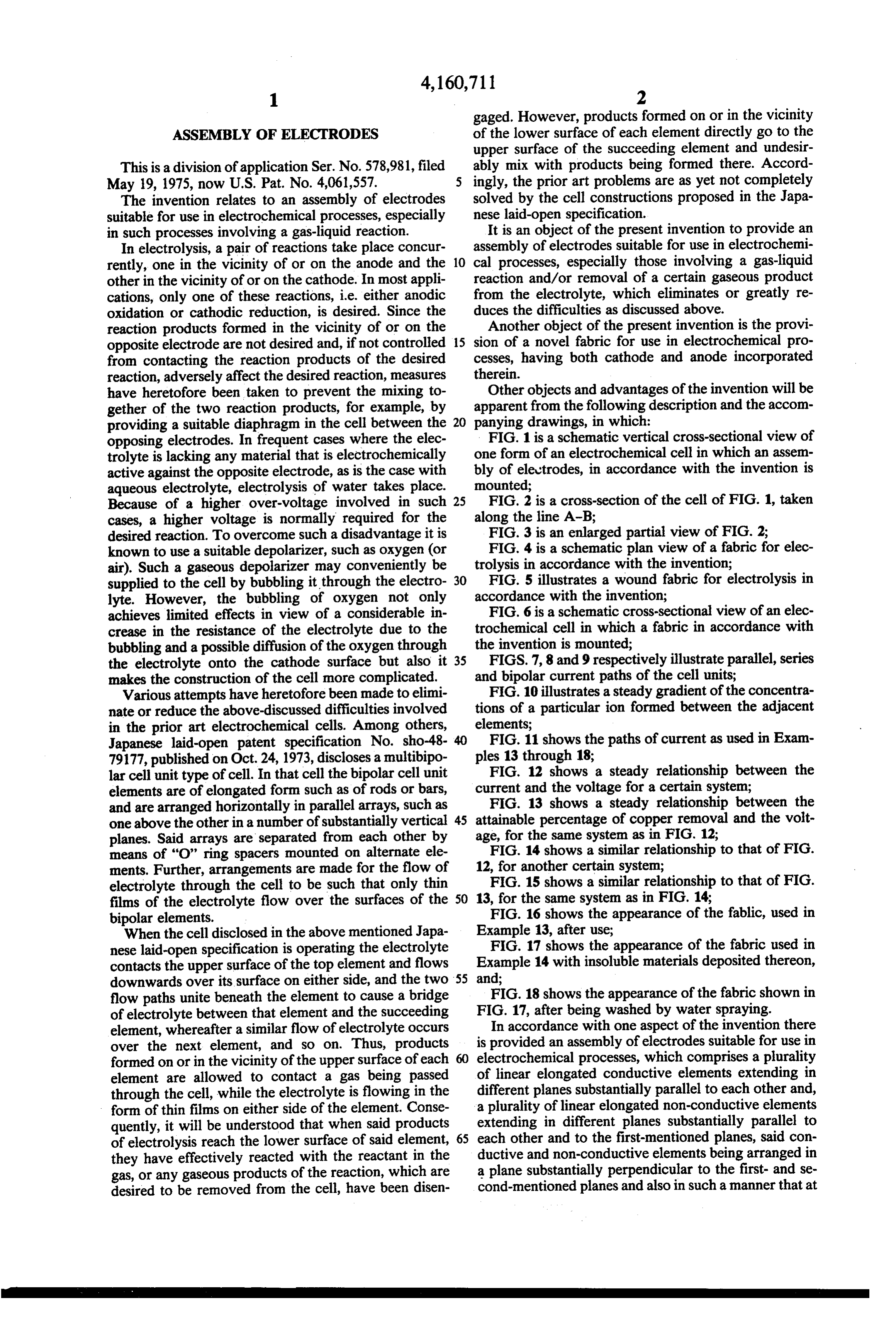
This is a division of application Ser. No. 578,981, filed ably mix with products being formed there. Accord May 19, 1975, now U.S. Pat. No. 4,061,557. ingly, the prior art problems are as yet not completely The invention relates to an assembly of electrodes solved by the cell constructions proposed in the Japa suitable for use in electrochemical processes, especially nese laid-open specification.
in such processes involving a gas-liquid reaction. It is an object of the present invention to provide an In electrolysis, a pair of reactions take place concur assembly of electrodes suitable for use in electrochemi rently, one in the vicinity of or on the anode and the 10 cal processes, especially those involving a gas-liquid other in the vicinity of or on the cathode. In most appli reaction and/or removal of a certain gaseous product cations, only one of these reactions, i.e. either anodic from the electrolyte, which eliminates or greatly re oxidation or cathodic reduction, is desired. Since the duces the difficulties as discussed above. reaction products formed in the vicinity of or on the Another object of the present invention is the provi opposite electrode are not desired and, if not controlled 15 sion of a novel fabric for use in electrochemical pro from contacting the reaction products of the desired cesses, having both cathode and anode incorporated reaction, adversely affect the desired reaction, measures therein.
have heretofore been taken to prevent the mixing to Other objects and advantages of the invention will be gether of the two reaction products, for example, by apparent from the following description and the accom providing a suitable diaphragm in the cell between the 20 panying drawings, in which:
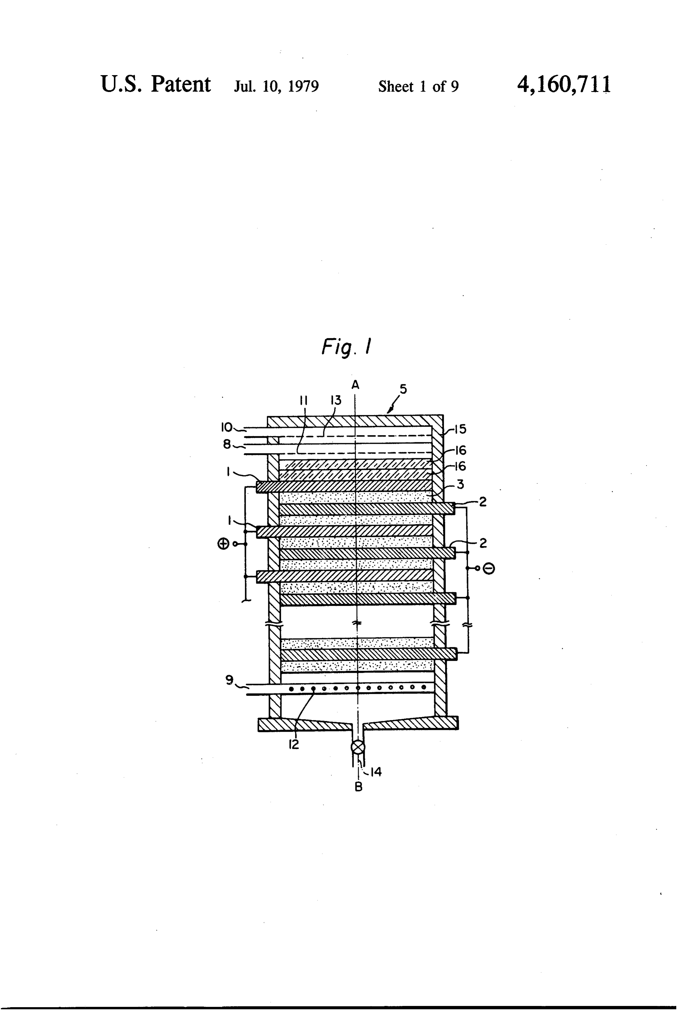
opposing electrodes. In frequent cases where the elec FIG. 1 is a schematic vertical cross-sectional view of trolyte is lacking any material that is electrochemically one form of an electrochemical cell in which an assem active against the opposite electrode, as is the case with bly of electrodes, in accordance with the invention is aqueous electrolyte, electrolysis of water takes place. mounted;
Because of a higher over-voltage involved in such 25 FIG. 2 is a cross-section of the cell of FIG. 1, taken cases, a higher voltage is normally required for the along the line A-B;
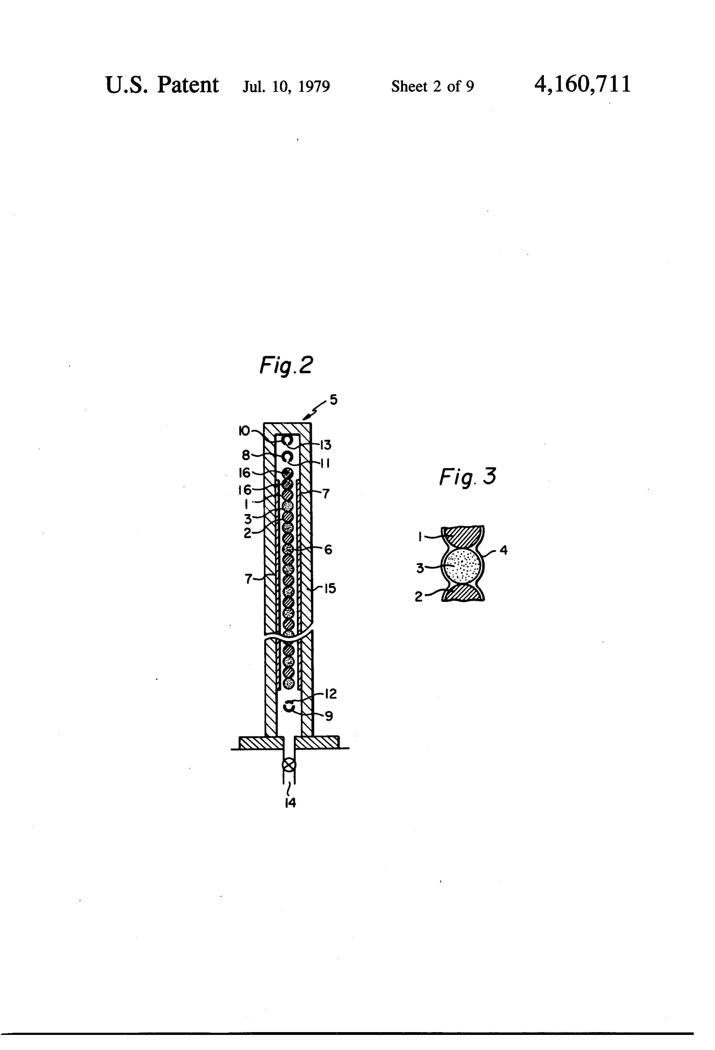
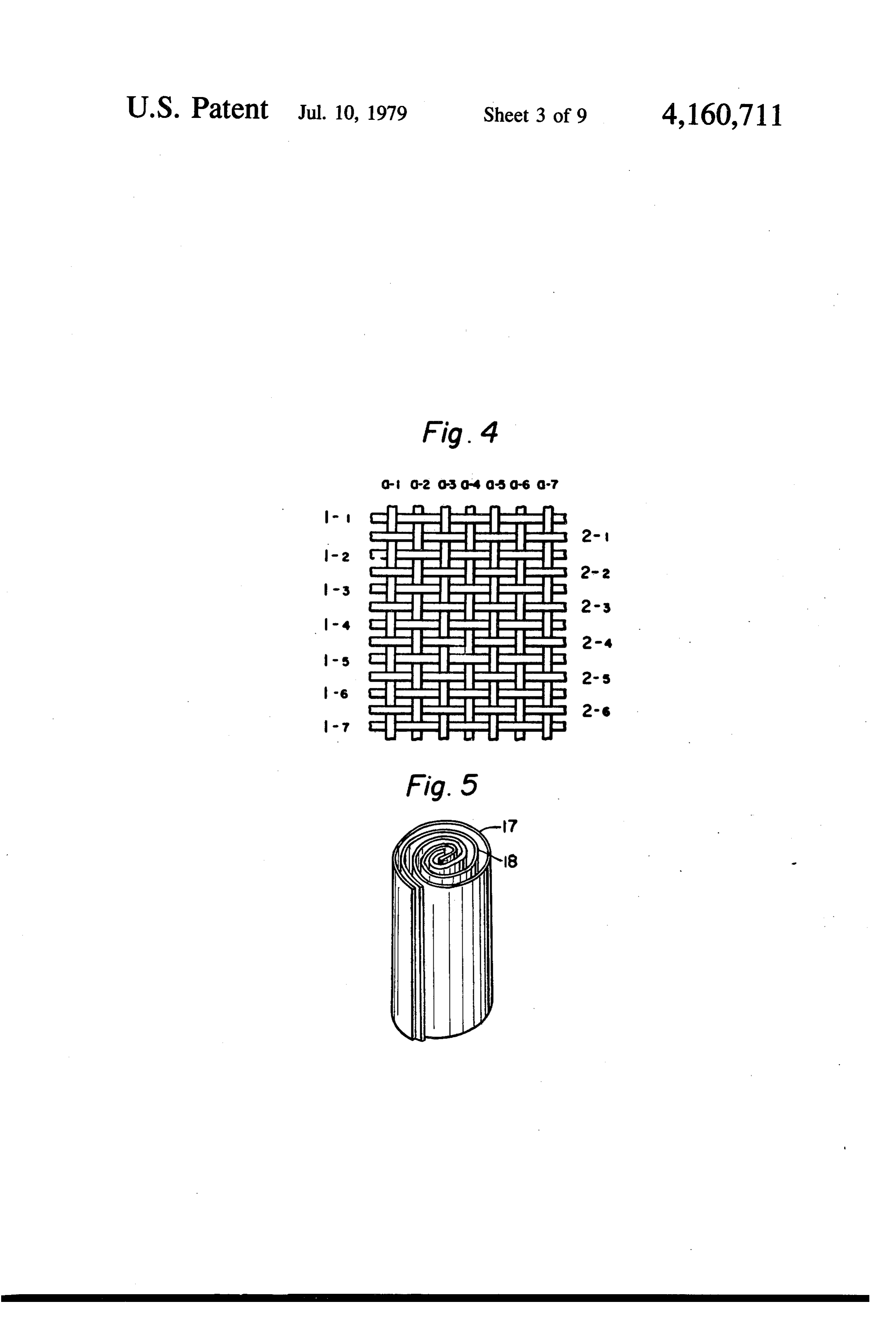
desired reaction. To overcome such a disadvantage it is FIG. 3 is an enlarged partial view of FIG. 2; known to use a suitable depolarizer, such as oxygen (or FIG. 4 is a schematic plan view of a fabric for elec air). Such a gaseous depolarizer may conveniently be trolysis in accordance with the invention; supplied to the cell by bubbling it through the electro 30 FIG. 5 illustrates a wound fabric for electrolysis in lyte. However, the bubbling of oxygen not only accordance with the invention;
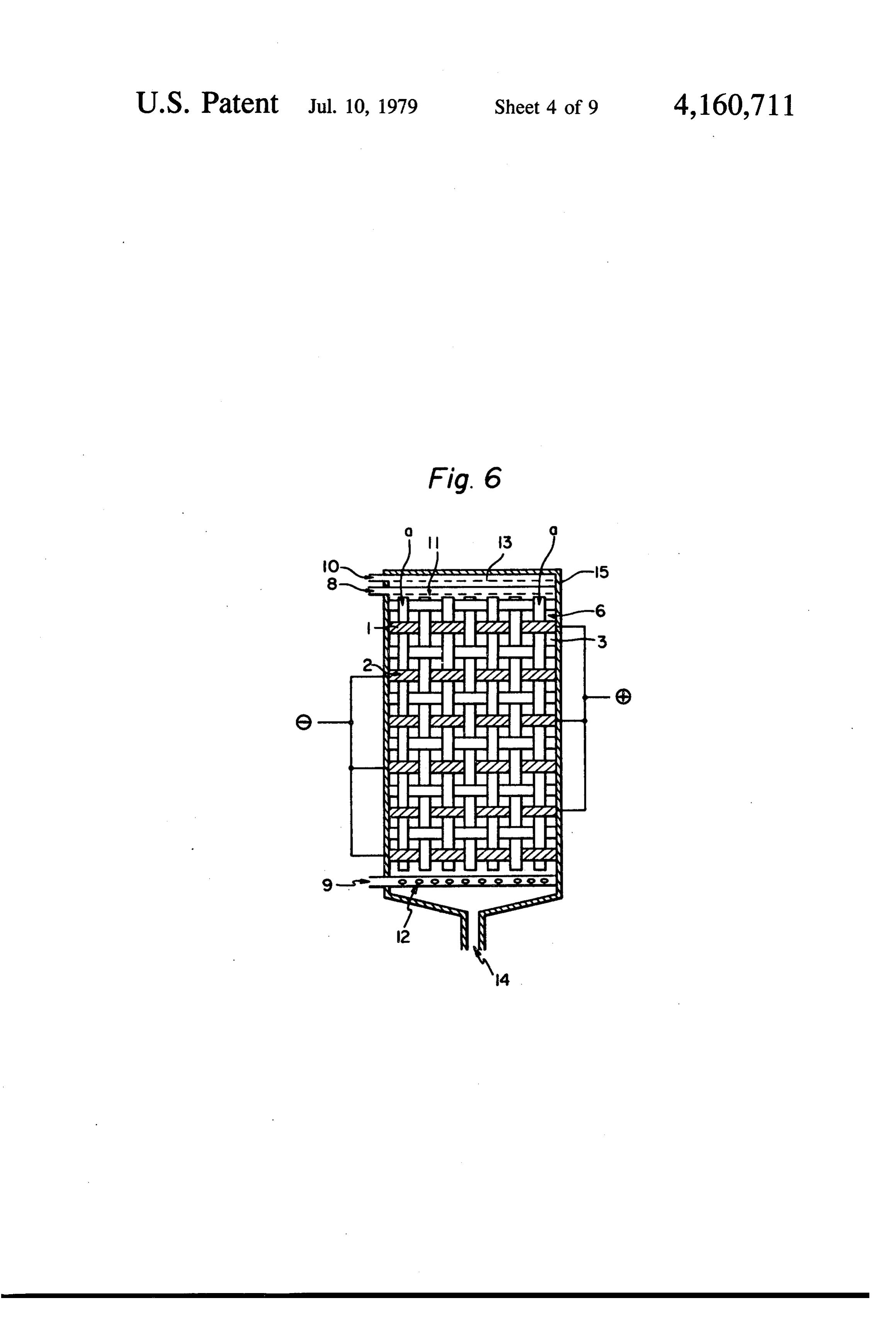
achieves limited effects in view of a considerable in FIG. 6 is a schematic cross-sectional view of an elec crease in the resistance of the electrolyte due to the trochemical cell in which a fabric in accordance with bubbling and a possible diffusion of the oxygen through the invention is mounted;
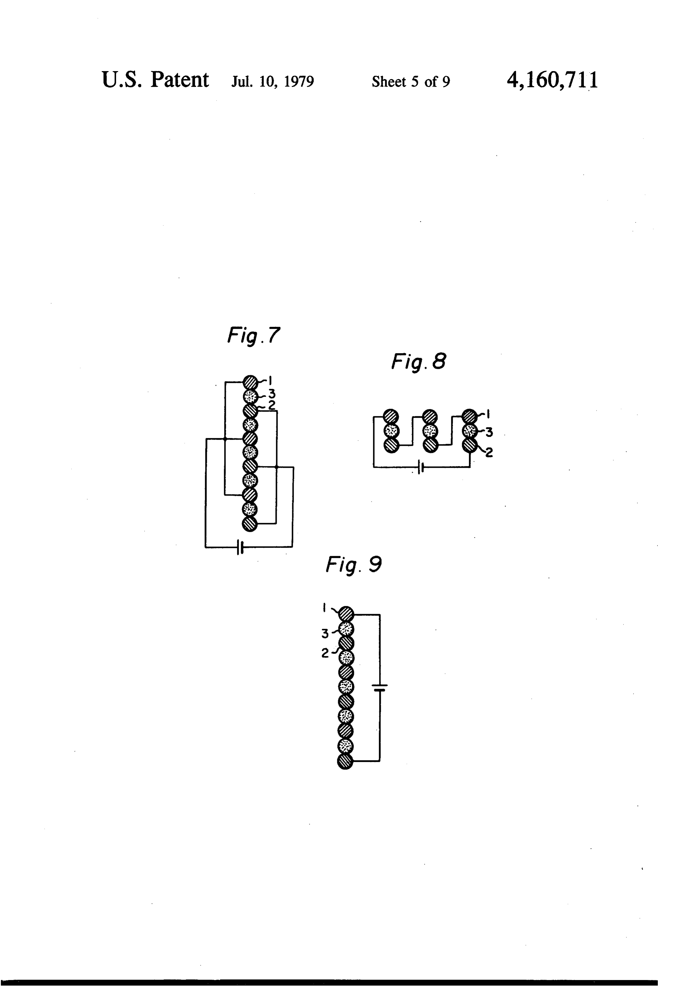
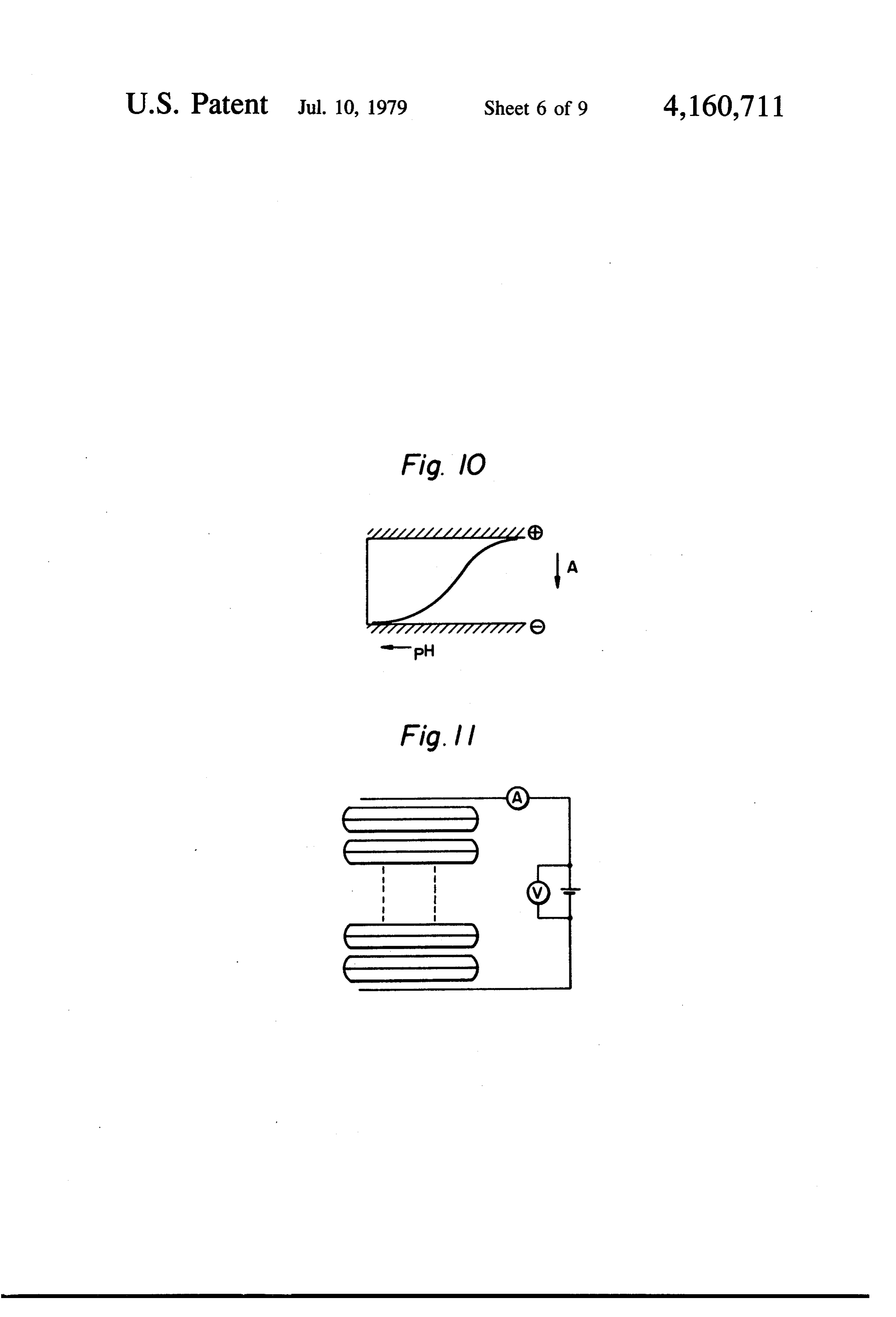
the electrolyte onto the cathode surface but also it 35 FIGS. 7, 8 and 9 respectively illustrate parallel, series makes the construction of the cell more complicated. and bipolar current paths of the cell units; Various attempts have heretofore been made to elimi FIG. 10 illustrates a steady gradient of the concentra nate or reduce the above-discussed difficulties involved tions of a particular ion formed between the adjacent in the prior art electrochemical cells. Among others, elements;
Japanese laid-open patent specification No. sho-48 40 FIG. 11 shows the paths of current as used in Exam 791.77, published on Oct. 24, 1973, discloses a multibipo ples 13 through 18;
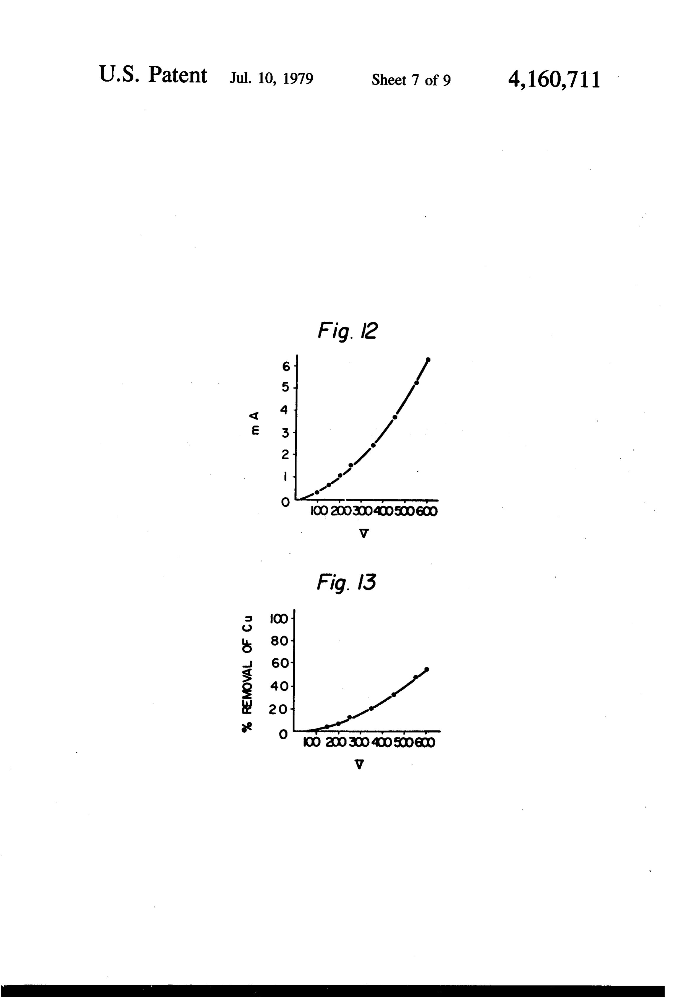
lar cell unit type of cell. In that cell the bipolar cell unit FIG. 12 shows a steady relationship between the elements are of elongated form such as of rods or bars, current and the voltage for a certain system; and are arranged horizontally in parallel arrays, such as FIG. 13 shows a steady relationship between the one above the other in a number of substantially vertical 45 attainable percentage of copper removal and the volt planes. Said arrays are separated from each other by age, for the same system as in FIG. 12; means of "O' ring spacers mounted on alternate ele FIG. 14 shows a similar relationship to that of FIG. ments. Further, arrangements are made for the flow of 12, for another certain system;
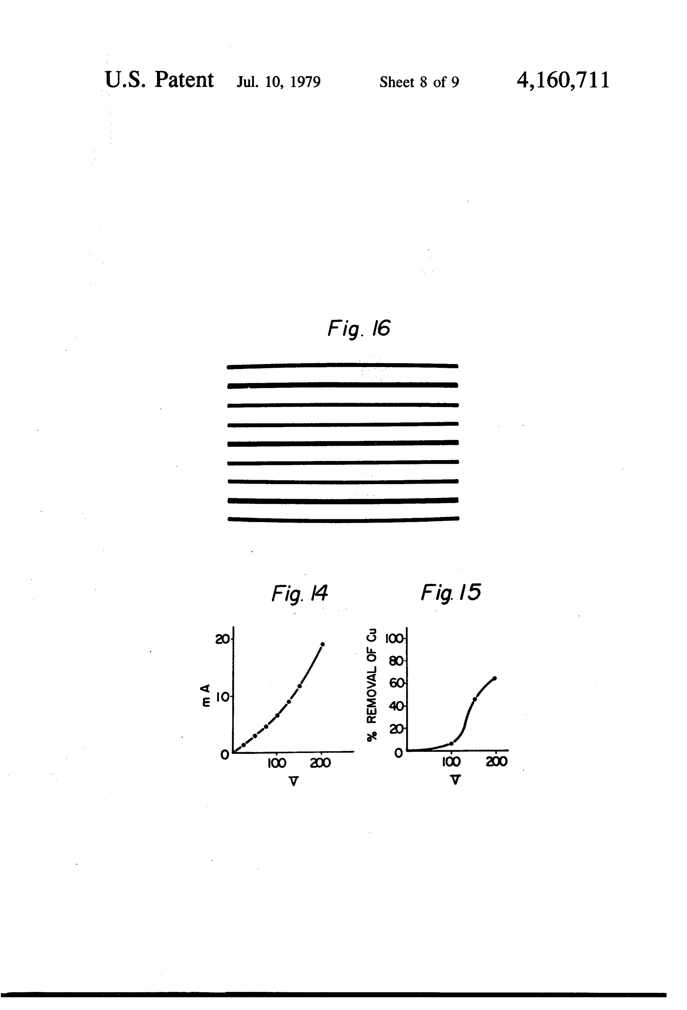
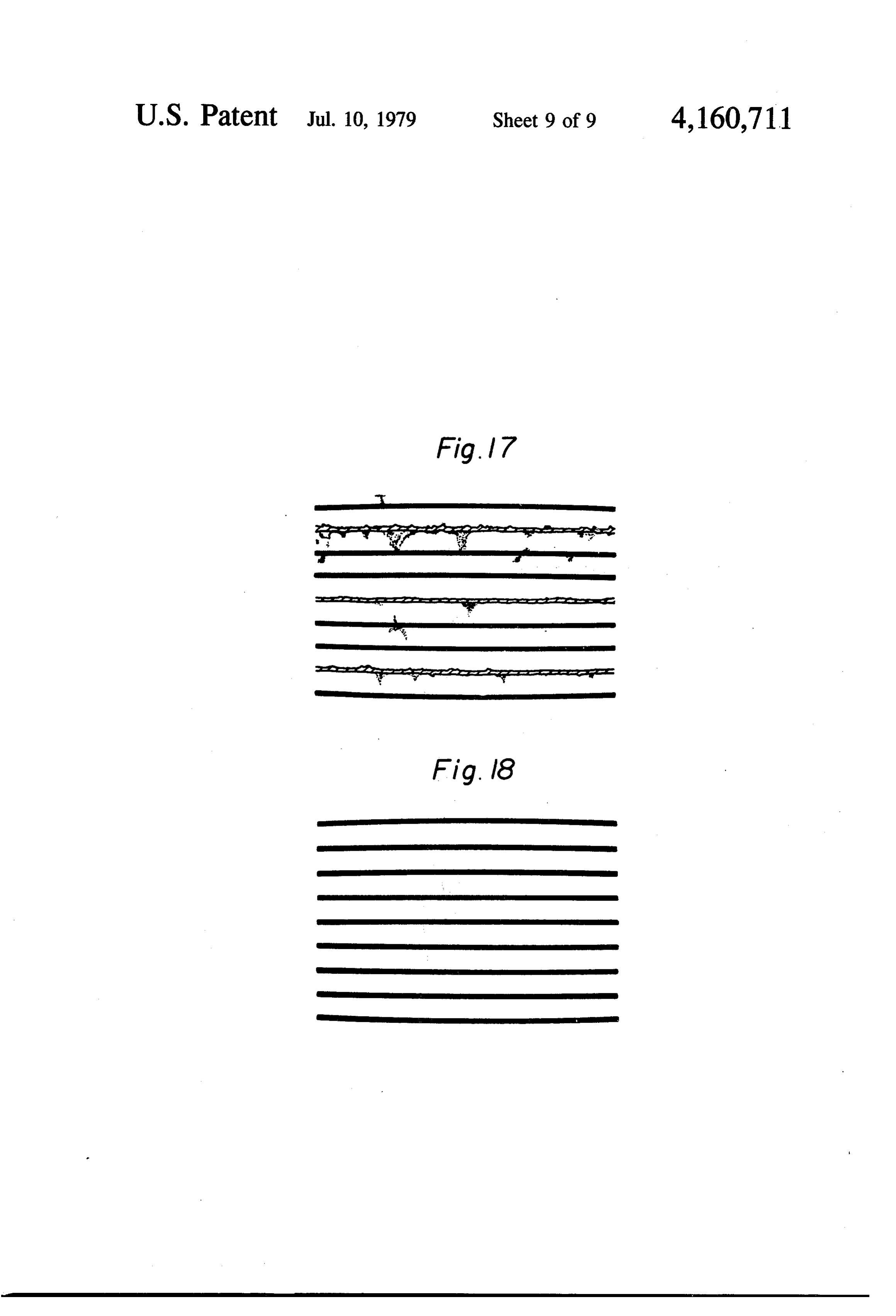
electrolyte through the cell to be such that only thin FIG. 15 shows a similar relationship to that of FIG. films of the electrolyte flow over the surfaces of the 50 13, for the same system as in FIG. 14; bipolar elements. FIG. 16 shows the appearance of the fablic, used in When the cell disclosed in the above mentioned Japa Example 13, after use;
nese laid-open specification is operating the electrolyte FIG. 17 shows the appearance of the fabric used in contacts the upper surface of the top element and flows Example 14 with insoluble materials deposited thereon, downwards over its surface on either side, and the two 55 and;
flow paths unite beneath the element to cause a bridge FIG. 18 shows the appearance of the fabric shown in of electrolyte between that element and the succeeding FIG. 17, after being washed by water spraying. element, whereafter a similar flow of electrolyte occurs In accordance with one aspect of the invention there over the next element, and so on. Thus, products is provided an assembly of electrodes suitable for use in formed on or in the vicinity of the upper surface of each 60 electrochemical processes, which comprises a plurality element are allowed to contact a gas being passed of linear elongated conductive elements extending in through the cell, while the electrolyte is flowing in the different planes substantially parallel to each other and, form of thin films on either side of the element. Conse a plurality of linear elongated non-conductive elements quently, it will be understood that when said products 65 extending in different planes substantially parallel to of electrolysis reach the lower surface of said element, each other and to the first-mentioned planes, said con they have effectively reacted with the reactant in the ductive and non-conductive elements being arranged in gas, or any gaseous products of the reaction, which are a plane substantially perpendicular to the first- and se desired to be removed from the cell, have been disen cond-mentioned planes and also in such a manner that at
Page 12
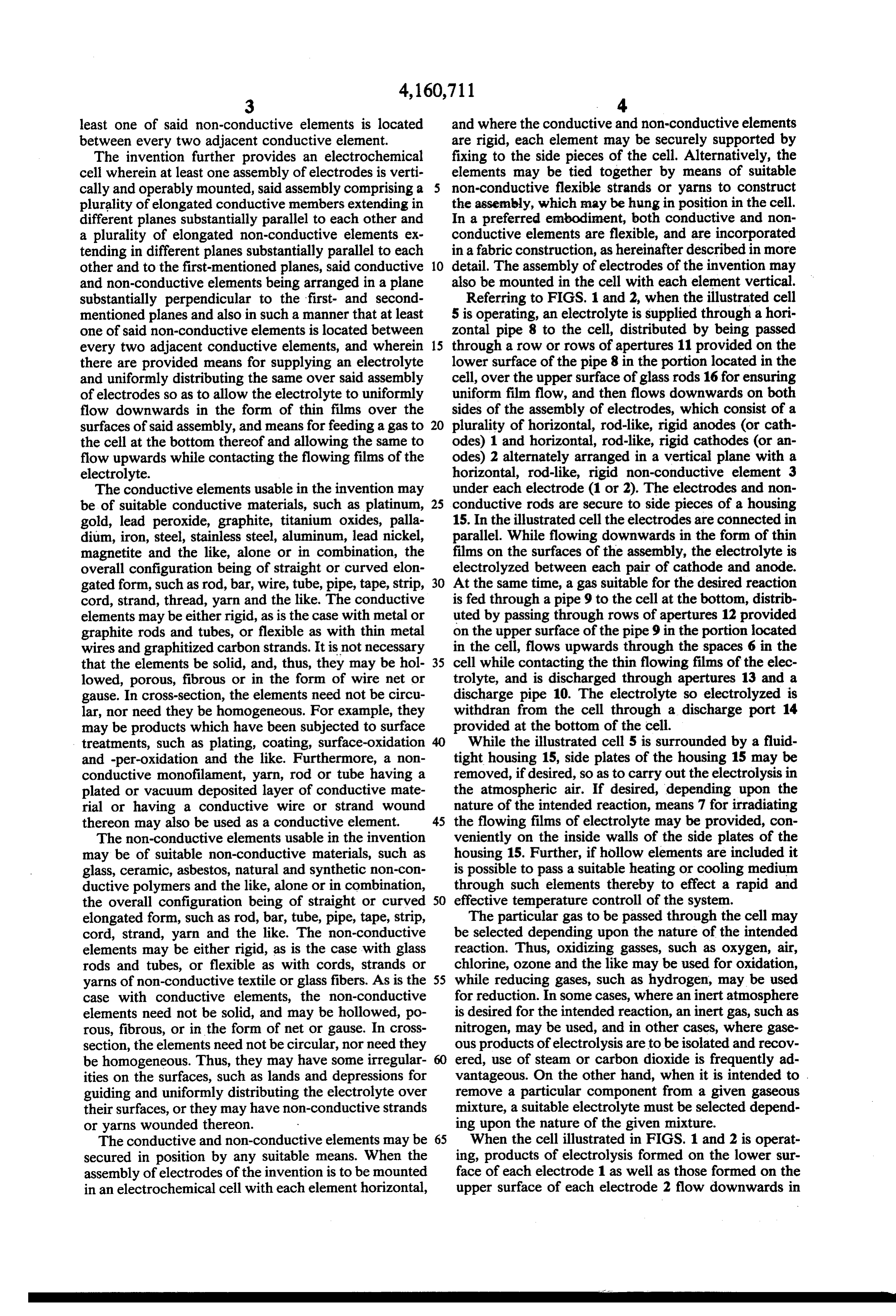
least one of said non-conductive elements is located and where the conductive and non-conductive elements between every two adjacent conductive element. are rigid, each element may be securely supported by The invention further provides an electrochemical fixing to the side pieces of the cell. Alternatively, the cell wherein at least one assembly of electrodes is verti elements may be tied together by means of suitable cally and operably mounted, said assembly comprising a non-conductive flexible strands or yarns to construct plurality of elongated conductive members extending in the assembly, which may be hung in position in the cell. different planes substantially parallel to each other and In a preferred embodiment, both conductive and non a plurality of elongated non-conductive elements ex conductive elements are flexible, and are incorporated tending in different planes substantially parallel to each in a fabric construction, as hereinafter described in more other and to the first-mentioned planes, said conductive 10 detail. The assembly of electrodes of the invention may and non-conductive elements being arranged in a plane also be mounted in the cell with each element vertical. substantially perpendicular to the first- and second Referring to FIGS. 1 and 2, when the illustrated cell mentioned planes and also in such a manner that at least 5 is operating, an electrolyte is supplied through a hori one of said non-conductive elements is located between Zontal pipe 8 to the cell, distributed by being passed every two adjacent conductive elements, and wherein 15 through a row or rows of apertures 11 provided on the there are provided means for supplying an electrolyte lower surface of the pipe 8 in the portion located in the and uniformly distributing the same over said assembly cell, over the upper surface of glass rods 16 for ensuring of electrodes so as to allow the electrolyte to uniformly uniform film flow, and then flows downwards on both flow downwards in the form of thin films over the sides of the assembly of electrodes, which consist of a surfaces of said assembly, and means for feeding a gas to 20 plurality of horizontal, rod-like, rigid anodes (or cath the cell at the bottom thereof and allowing the same to odes) 1 and horizontal, rod-like, rigid cathodes (or an flow upwards while contacting the flowing films of the odes) 2 alternately arranged in a vertical plane with a electrolyte. horizontal, rod-like, rigid non-conductive element 3 The conductive elements usable in the invention may under each electrode (1 or 2). The electrodes and non be of suitable conductive materials, such as platinum, 25 conductive rods are secure to side pieces of a housing gold, lead peroxide, graphite, titanium oxides, palla 15. In the illustrated cell the electrodes are connected in dium, iron, steel, stainless steel, aluminum, lead nickel, parallel. While flowing downwards in the form of thin magnetite and the like, alone or in combination, the films on the surfaces of the assembly, the electrolyte is overall configuration being of straight or curved elon electrolyzed between each pair of cathode and anode. gated form, such as rod, bar, wire, tube, pipe, tape, strip, 30 At the same time, a gas suitable for the desired reaction cord, strand, thread, yarn and the like. The conductive is fed through a pipe 9 to the cell at the bottom, distrib elements may be either rigid, as is the case with metal or uted by passing through rows of apertures 12 provided graphite rods and tubes, or flexible as with thin metal on the upper surface of the pipe 9 in the portion located wires and graphitized carbon strands. It is not necessary in the cell, flows upwards through the spaces 6 in the that the elements be solid, and, thus, they may be hol 35 cell while contacting the thin flowing films of the elec lowed, porous, fibrous or in the form of wire net or trolyte, and is discharged through apertures 13 and a gause. In cross-section, the elements need not be circu discharge pipe 10. The electrolyte so electrolyzed is lar, nor need they be homogeneous. For example, they withdran from the cell through a discharge port 14 may be products which have been subjected to surface provided at the bottom of the cell.
treatments, such as plating, coating, surface-oxidation While the illustrated cell 5 is surrounded by a fluid and -per-oxidation and the like. Furthermore, a non tight housing 15, side plates of the housing 15 may be conductive monofilament, yarn, rod or tube having a removed, if desired, so as to carry out the electrolysis in plated or vacuum deposited layer of conductive mate the atmospheric air. If desired, depending upon the rial or having a conductive wire or strand wound nature of the intended reaction, means 7 for irradiating thereon may also be used as a conductive element. 45 the flowing films of electrolyte may be provided, con The non-conductive elements usable in the invention veniently on the inside walls of the side plates of the may be of suitable non-conductive materials, such as housing 15. Further, if hollow elements are included it glass, ceramic, asbestos, natural and synthetic non-con is possible to pass a suitable heating or cooling medium ductive polymers and the like, alone or in combination, through such elements thereby to effect a rapid and the overall configuration being of straight or curved 50 effective temperature controll of the system. elongated form, such as rod, bar, tube, pipe, tape, strip, The particular gas to be passed through the cell may cord, strand, yarn and the like. The non-conductive be selected depending upon the nature of the intended elements may be either rigid, as is the case with glass reaction. Thus, oxidizing gasses, such as oxygen, air, rods and tubes, or flexible as with cords, strands or chlorine, ozone and the like may be used for oxidation, yarns of non-conductive textile or glass fibers. As is the 55 while reducing gases, such as hydrogen, may be used case with conductive elements, the non-conductive for reduction. In some cases, where an inert atmosphere elements need not be solid, and may be hollowed, po is desired for the intended reaction, an inert gas, such as rous, fibrous, or in the form of net or gause. In cross nitrogen, may be used, and in other cases, where gase section, the elements need not be circular, nor need they ous products of electrolysis are to be isolated and recov be homogeneous. Thus, they may have some irregular ered, use of steam or carbon dioxide is frequently ad ities on the surfaces, such as lands and depressions for vantageous. On the other hand, when it is intended to . guiding and uniformly distributing the electrolyte over remove a particular component from a given gaseous their surfaces, or they may have non-conductive strands mixture, a suitable electrolyte must be selected depend or yarns wounded thereon. ing upon the nature of the given mixture. The conductive and non-conductive elements may be 65 When the cell illustrated in FIGS. 1 and 2 is operat secured in position by any suitable means. When the ing, products of electrolysis formed on the lower sur assembly of electrodes of the invention is to be mounted face of each electrode 1 as well as those formed on the in an electrochemical cell with each element horizontal, upper surface of each electrode 2 flow downwards in
Page 13
the form of thin films 4 before the products reach the two or more adjacent conductive elements may be opposite electrode (see FIG. 3). short-circuited so as to form one electrode. In the preferred embodiments, the assembly of elec The assemblies of electrodes, fabrics for electrolysis trodes in accordance with the invention comprises a and electrochemical cells described herein are applica woven or knitted fabric of non-conductive material and 5 ble to any reactions which have heretofore been carried a plurality of elongated conductive elements are incor out in conventional electrochemical processes. They porated therein substantially in parallel and spaced are particularly suitable for use in electrochemical pro apart from each other. The conductive elements are cesses involving a gas-liquid reaction or formation of preferably flexible and may be incorporated in the base gaseous products to be removed. Among others, the fabric of non-conductive material during or after the 10 invention may be applied to the following reactions. manufacture of the fabric. (1) Removal of metal ions by oxidation or reduction, FIG. 4 schematically illustrates a fabric for electroly for example, removal of metals (such as Cu, Cd, Cr, Co, sis in accordance with the invention. The fabric is a Hg, Zn, Mn, Fe and the like) from waste liquids con plain fabric in which the warp consists of non-conduc taining the same.
tive yarns a-1 to a-7 such as polyester, cotton, or glass 15 (2) Treatment of waste liquids containing organic yarns while the weft consists of similar non-conductive contaminants, such as waste liquids from dye or dyeing yarns 1-1 to 1-7 and elongated conductive elements 2-1 industries or from food industries.
to 2-6, such as strands of graphatized carbon filaments (3) Deodorization, for example, removal of hydrogen or platinum wires, the adjacent conductive elements sulfide, mercaptans, sulfur dioxide and the like. being separated by at least one non-conductive yarn. 20 (4) Desulfurization and denitrogenation of waste or While the illustrated fabric for electrolysis is a plain exhaust gases.
fabric, woven fabrics of other weave constructions and (5) Destruction of colloidal dispersions, such as de knitted fabrics may also be utilized. Furthermore, the struction of oil-in-water or water-in-oil emulsions and, conductive elements may be incorporated into the pre floculation and removal of colloidally dispersed parti formed base fabric, for example, by insertion, sewing, 25 cles.
adhesion, or coating. The fabric for electrolysis in ac (6) Manufacturing processes based on direct or indi cordance with the invention has the following advan rect anodic oxidation or cathodic reduction, including, tages. for example, formation of hypochlorites, chlorates, (1) Formation of a uniform film flow of electrolyte is per-chlorates, sodium hydroxide and chlorine by the facilitated. 30 electrolysis of an aqueous solution of sodium chloride; (2) A larger surface area per unit weight of the elec production of permanganates from manganates; pro trode material may be achieved. duction of gluconates from gluconic acid; production of (3) Because of its flexibility, the electrode assembly succinates from maleic acid; production of hydroxylam may be used in a wound form, as shown in FIG. 5, in ine from nitric acid and the like.
which the numeral 17 designates the fabric for electrol 35 It has been found that the fabric for electrolysis and ysis according to the invention while the numeral 18 the cell, in which said fabric is mounted, are especially designates an insulating film such as a polyester film. useful in a continuous process for removing solutes (4) Since the base fabric bears loads, the assembly of from an aqueous solution containing the same dissolved electrodes has mechanical strength sufficient to be used therein, said solutes being capable of forming insoluble in electrochemical processes. 40 materials depending upon the pH of the solution. Thus, (5) Any desired length and width may readily be there in accordance with a special aspect of the invention, achieved. is provided a continuous process for the removal (6) Manufacturing, handling and using of the elec of solutes from an aqueous solution containing the same trode assembly are simple and easy. dissolved therein, said solutes being capable of forming FIG. 6 illustrates an electrochemical cell in which a 45 insoluble materials depending upon the pH of the solu fabric for electrolysis according to the invention in tion, which process comprises the steps of causing said mounted. In FIG. 6, the same reference numerals are aqueous solution to flow downwards in the form of thin used as in FIG. 1 to designate the same parts of the cells. films over a vertical fabric of non-conductive material The letter a designates a warp yarn of the fabric. Thus, in which a plurality of elongated conductive elements according to a further aspect of the invention there is 50 are incorporated so as to be parallel and spaced apart provided an electrochemical cell wherein at least one from each other, and applying a potential to said con assembly of electrodes in vertically and operably ductive elements so as to produce a suitable steady pH mounted, said assembly comprising a woven or knitted distribution in the thin films of the solution flowing fabric of non-conductive material wherein a plurality of downwards over the fabric, whereby said solutes are elongated conductive elemtns are incorporated so as to 55 insolubilized and deposited on predetermined zones of be substantially parallel and spaced apart from each said fabric irrespectively of any anodic and cathodic other and in which cell there are provided means for reactions.
supplying an electrolyte and uniformly distributing the When an electrolyte is allowed to flow from one same over said fabric so as to allow the electrolyte to electrode to the other electrode and a suitable potential uniformly flow downwards in the form of thin films is applied to the electrodes, a steady distribution or over the surfaces of said fabric and means for feeding a gradient of pH is formed in the flowing electrolyte gas to the cell at the bottom thereof and allowing the between the electrodes, as illustrated in FIG. 10, in same to flow upwards while contacting the flowing which the arrow A designates the direction of flow of films of the electrolyte. the electrolyte. The profile of pH depends on various In the cells of the invention the electrodes may be factors, including the composition and concentration of connected in any suitable manner. They may be con the electrolyte, the applied voltage, the current density, nected so as to form parallel, series or bipolar paths, as the temperature, the direction and rate of flow of the illustrated in FIGS. 7, 8 and 9, respectively. If desired, electrolyte, the distance between the electrodes and the
Page 14
nature and shape of the electrodes. By controlling these 1.4 ppm of copper. The percentage of copper removal factors, a suitable gradient or distribution of pH may be was 98.6%.
produced in the flowing electrolyte between the elec trodes so that the solutes in the electrolyte to be re EXAMPLE 3 moved may be insolubilized in a zone where the pH is 5 An apparatus as used in Example 1 was used except suitable to cause the solute to precipitate. We propose to that a DC voltage of 4000 V was applied between the use the fabric for electrolysis of the invention in such a top and bottom electrodes with the remaining elec process. The electrodes are preferably connected to trodes allowed to serve as bipolar electrodes. About a provide a multi-bipolar system. The above-mentioned 102 molar aqueous solution of sodium chloride con precipitation takes place over predetermined areas of 10 taining 10 ppm of CN as sodium cyanide was caused the fabric, in most case on and in the vicinity of anodes to uniformly flow down through the apparatus at a rate or cathodes, and independently of the anodic and ca of 60 ml/min. while forming a flowing film on the rods, thodic reactions involved. The deposited insoluble ma which film was contacted with air fed to the apparatus terials are different from the products of electrolysis 15 from the bottom thereof at a rate of 1,000 ml/min. The and can easily be disengaged from the fabric, e.g. by liquid leaving the apparatus was tested for CN by a mere water spraging. The fabric may be re-used. Be 0.5 method in accordance with JIS-K 0102-29. It contained sides metal ions, certain organic acids, amines, amino ppm of CN-.
acids, proteins and other colloidal particles may be The above procedure was repeated except that the advantageously removed by the proposed process from DC source was replaced with a 20 Hz alternating and an aqueous solution or dispersion containing the same. 20 pulse source with other conditions remaining substan As is well-known, metal ions, for example, copper ion, tially the same. A similar result was obtained. may be removed from an aqueous solution containing EXAMPLE 4 the same by alkaline treatment. Such a treatment re quired, however, use of amounts of alkali and neutral 25 fate was supplied to an aqueous
About a 102 molar apparatus solution of sodium sul as used in Example 1 ization of the treated solution prior to the disposal thereof. Whereas the process proposed herein does from the top thereof at a rate of 60 ml/min., allowed to uniformly flow down through the apparatus while require neither use of such a chemical nor any after forming thin films on the rods, and electrolyzed by treatments. It has also been found that the proposed applying a sufficient DC voltage to the electrodes to process is especially effective when the solution to be 30 maintain the treated is relatively dilute and when it is operated with same time, a current density of about 1 mA/cm2. At the a relatively high current density. Accordingly, the pro ratio of 1:1 by volumeofwassulfur mixture dioxide and oxygen in a fed to the apparatus from the posed process is particularly useful in removing or re bottom thereof at a rate of 600 ml/min. or 60 ml/min. ducing a trace of metal ions from waste liquids contain and allowed ing the same or in recovering the last crops of the prod 35 electrolyzed.toThe contact the flowing films of liquid being sulfur dioxide and oxygen were ab ucts from aqueous solution containing the same at the sorbed by the electrolyte films and the former was elec last step of the manufacture thereof.
The invention will be further described by the foll apparatus contained the sulfurictheacid trolytically oxidized whereby liquid leaving the so formed and lowing illustrative Examples. exhibited a strong acidity. The sulfuric acid content of EXAMPLE 1. the liquid was determined by titration with an aqueous solution
The apparatus used was a type as illustrated in FIG. calculation of patassium hydroxide. The measurement and 1, in which the electrode assembly comprised one hun sulfur dioxide revealed that the percentage of removal of was 38% with the flow rate of 600 dred horizontal graphite rods and ninty nine horizontal ml/min. and 75% glass rods alternately arranged in a vertical plane. Each 45 During the operationwithof the flow rate of 60 ml/min.
this Example the voltage varied rod had a diameter of 10 mm and an effective length of within the range between 32 and 1 volts. 270 mm. About a 10-2 molar aqueous solution of so dium chloride containing 100 ppm of copper as copper EXAMPLE 5 sulfate was supplied to the apparatus from the top Using an apparatus as used in Example 1, a four molar thereof at a rate of 60 ml/min and allowed to uniformly 50 aqueous solution of sodium chloride was electrolyzed in flow down through the apparatus while forming thin a film flow state in an air stream at a temperature of 35 films on the rods. At the same time a DC voltage of 40 to 40 C. A DC voltage of 6 V was applied to the elec V was applied to the graphite electrodes connected in trodes. 250 ml of the electrolyte was circulated through parallel and the flowing films of electrolyte were con the apparatus for 30 minutes at a rate of 60 ml/min. At tacted with a stream of hydrogen, which was fed to the 55 the end of the period, the liquid leaving the apparatus apparatus from the bottom at a rate of 600 ml/min. The was analyzed by a method in accordance with JIS K atomic absorption analysis for copper of the liquid leav 8208, revealing that it contained 38% by weight sodium ing the apparatus showed that it contained 1.5 ppm of copper, revealing that the percentage of copper re chlorate. During the operation the current varied within the range between 2 and 4 A.
moval was 98.5%. During the operation the current 60 varied within the range between 250 and 450 mA. EXAMPLE 6 EXAMPLE 2 Using an apparatus as used in Example 1 except that the housing 15 was removed so as to expose the flowing
The procedure as described in Example 1 was re film of electrolyte to the atmospheric air, about a 10-2 peated except that the graphite rods for cathodes were 65 molar aqueous solution of sodium chloride containing replaced by stainless steel rods and the glass rods were 100 ppm of methylene blue was allowed to flow down replaced by polyvinyl chloride pipes wrapped with through the apparatus in a film flow state at a rate of 60 cotton cloth. The liquid leaving the apparatus contained ml/min, while a DC voltage of 50 V was applied to the
Page 15
electrodes. Oxygen in the air was absorbed by the flow as anodes and cathodes, respectively, a rectangular ing film of electrolyte and acted as a depolarizer. Color fabric for electrolysis having a dimension of 50cm x 1m imetric analysis of the electrolytically oxidised aqueous was cut, with the electrodes extending substantially solution of methylene blue by means of a Hitachi spec parallel to the shorter sides of the cut fabric. trophotometer Model 139 revealed that the percentage 5 The fabric for electrolysis was mounted in an appara of decoloration was 73%. During the operation, the tus as illustrated in FIG. 6, with the electrodes horizon current varied within the range between 350 and 500 tal and connected in parallel. A 10-2 molar aqueous mA. solution of sodium chloride containing 100 ppm of
EXAMPLE 7
methylene blue was supplied to the apparatus from the 10 top thereof at a rate of 30 ml/min. and allowed to uni
The procedure as described in Example 6 was re formly flow down through the cell in the form of thin peated except that the flowing film of electrolyte was films. At the same time, air was supplied to the appara irradiated by means of a mercury lamp. The enhanced tus at a rate of 1,000 ml/min. and a DC voltage of 25 V percentage of decoloration of 93% was attained. was applied between anodes and cathodes. Calorimetric The procedure as described in Example 7 was re- 15 analysis of the electrolytically oxidized solution by peated except that the flowing film of electrolyte was means of a Hitachi spectrophotometer, Model 139, re irradiated with radiation from cobalt 60 and the rate of vealed that the percentage of decoloration was 82%. flow of the electrolyte was increased to 100 ml/min. In During the operation, the current varied within the spite of the increased rate of flow, the enhanced per range between 2 and 4 A.
centage of decoloration of 92% was obtained. 20 EXAMPLE 12
EXAMPLE 8
From a fabric, described in Example 10, having the
Using a poly (ethylene terephthalate) filamentary carbon threads as electrodes, a rectangular fabric for yarn having a thickness of about 200 denier as warp and, electrolysis having a dimension of 50 cm x 1 m was cut, the same kind of polyester yarn and a platinum wire 25 with the carbon threads extending substantially paralles having a diameter of 0.01 cm as weft, a plain woven to the shorter sides of the cut fabric. fabric for electrolysis having a longitudinal length of 5 The fabric for electrolysis was mounted in an appara m and a transverse width of 1 m was prepared, in which tus as illustrated in FIG. 6, with the electrodes horizon 5000 platinum wires were incorporated with a spacing tal and connected in parallel. A 102 molar aqueous of about 1 mm between the centers of each adjacent two 30 solution of sodium sulfate was supplied to the apparatus plantinum wires. The weight of the platinum used was from the top thereof at a rate of 60 ml/min., allowed to about 930 g, which was slightly in excess of the theoreti uniformly flow down through the apparatus in the form cal weight required for such a construction. The total of thin films, and electrolyzed by applying a DC voltage surface of the platinum electrode was calculated as to the electrodes sufficient to maintain a current of 3 A. being approximately 17300 cm2. The fabric so prepared 35 At the same time, 21 of a mixture of sulfur dioxide and was flexible and had sufficient strength to be used as an oxygen in a ratio of 1:1 by volume was fed to the appa assembly of electrodes in electrochemical processes. ratus from the bottom thereof at a rate of 600 ml/min. EXAMPLE 9 and allowed to contact the flowing films of liquid being electrolyzed. The mixed gas which had passed through
Using a cotton yarn of 30 count as warp and, such the 40 the apparatus was recycled and the operation was con same kind of yarn and a platinum wire as weft, a plain tinued for 10 minutes. The sulfur dioxide and oxygen woven fabric was prepared, in which every adjacent were absorbed by the electrolyte films and the former two platinum wires were separated by two cotton yarns was electrically oxidized, whereby the liquid leaving so that the distance between the adjacent platinum the apparatus contained the sulfuric acid so formed and wires was about 1.8 mm. The fabric so prepared was 45 exhibited a strong acidity. The sulfuric acid content of flexible and had sufficient strength to be used as an the liquid was determined by titration with an aqueous assembly of electrodes in electrochemical processes. solution of potassium hydroxide. The measurement and EXAMPLE 10 calculation revealed that the percentage of removal of sulfur dioxide was 73%. During the operation of this
Similar plain woven fabrics were prepared, one 50 Example, the voltage varied within the range between 1 wherein the warp consisted of cotton yarns of 30 count and 4 V.
while the weft consisted of the same kind of yarns and EXAMPLE 13 filamentary carbon threads of 1800 denier, each of said carbon threads in the weft being separated from the Using a poly (ethylene terephthalate) filamentary adjacent carbon threads by a distance of about 3 mm, 55 thread of about 200 denier as warp and, such a polyester and the other wherein the warp consisted of cotton yarn and a carbon thread of about 1800 denier as weft, yarns of 30 count while the weft consisted of the same a plain woven fabric having a width of 38 cm was pre kind of yarns and filamentary carbon threads of 1800 pared, in which the carbon threads were incorporated denier as anodes, and strands of steel fibers as cathodes, with 10 mm intervals. As illustrated in FIG. 11, every said anodes and cathodes being arranged alternately 60 carbon thread in the fabric, except for the top and bot with a spacing of about 3 mm between every two adja tom ones, were electrically short-circuited to form a cent electrodes. These fabrics were flexible and had bipolar element 39. Such bipolar elements were formed strength sufficient to be used as an assembly of elec between the top and bottom carbon thread to be used as trodes in electrochemical processes. current-carrying electrodes. The fabric soprepared was 65 mounted in a cell of a type as illustrated in FIG. 6 with
EXAMPLE 11
the carbon threads horizontal. The side plates of the cell
From a fabric, described in the preceding Example, were removed so as to expose the flowing films of elec having the carbon threads and the strands of steel fibers trolyte to the atmospheric air.
Page 16
A 103 molar aqueous solution of sodium chloride lyzed with a voltage of 300 V and a current of 26 mA. containing 100 ppm of copper as copper sulfate was The electrolyte leaving the cell contained 8 ppm of supplied to the cell at the top at a rate of 60 ml/min. and copper. This means a percentage of copper removal of allowed to uniformly flow down in the form of thin 60%. The removed insoluble deposits were analogous films along the fabric. The top and bottom carbon 5 to those of Example 14.
threads were connected to a DC source, with the top EXAMPLE 7 carbon threads connected to the positive pole of the source, and varying DC voltages were applied therebe The general procedure as described in Example 13 tween. The electrolyte leaving the cell was tested for was repeated except that a 101 molar aqueous solution the residual copper content by atomic absorption analy 10 of sodium chloride containing 20 ppm of iron as ferric sis. The current plotted against the voltage and the chloride was treated at a rate of 30 ml/min. with a attained percentage of copper removal plotted against voltage of 300 V and a current of 25 mA. Atomic ab the voltage are shown in FIGS. 12 and 13, respectively. sorption analysis for iron of the liquid leaving the cell Using a DC voltage of 250 V, the electrolysis as indicated that the percentage of iron removal was 90%. described above was continued for a period of 30 min 15 The deposits on the fabric were water-insoluble materi utes. The current was 1.5 mA. At the end of the period it was observed that the lowest cathode and the upper als, which could readily be removed from the fabric by water spraying.
most carbon thread of each bipolar element were plated with reduced copper on the upper side thereof. FIG. 16 EXAMPLE 18 shows such a fabric for electrolysis after use, in which 20 The general procedure as described in Example 13 solid lines represent carbon threads and hatched areas was repeated except that a 101 molar aqueous solution represent reduced copper which has been deposited on the lowert cathode and bipolar elements. As seen from of sodium chloride containing 20 ppm of aluminum as aluminum sulfate was treated at a rate of 30 ml/min.
FIG. 16, deposits obtainable under the conditions of this with a voltage of 400 V and a current of 47 mA. Atomic Example are primarily comprised of reduced copper. 25 absorption analysis for aluminum of the liquid leaving EXAMPLE 14 the cell indicated that the percentage of aluminum re The experiments as described in the preceding Exam moval was 88%. The deposits on the fabric were water insoluble materials which could easily be removed from ple were repeated except that the electrolyte was re the fabric.
placed by a 101 molar aqueous solution of sodium 30 chloride containing 100 ppm of copper as copper sul EXAMPLE 9 fate. The relationship between the current and voltage and that between the attained percentage of copper 13 was repeated except that theastop
The general the procedure described in Example and bottom carbon removal and the voltage are shown in FIGS. 14 and 15, respectively. 35 threads in the fabric were connected to the negative and Using a DC voltage of 200 V, the electrolysis as positive poles of the DC source, respectively, and a described above was continued for a period of 30 min 102 molar aqueous solution of sodium chloride con utes. The current was 18.5 mA. The results were essen taining 1% by weight of sodium laurate was treated at a tially distinct from those of the preceding Example. At rate of 45 ml/min. with a current of 10 mA. Water the end of the period, the fabric had an appearance as 40 insoluble materials had been deposited on and in the illustrated in FIG. 17. It was observed that flocs of vicinity of the lowest anode and the uppermost carbon various colors, including redish brown, dark brown, thread of each bipolar element. Measurement of the bluish green, greyish green and other, had been depos residual laurate in the treated liquid, in accordance with ited on and in the vicinity of the lowest cathode and the the standard oil and fat resting method prescribed by uppermost carbon thread of each bipolar element. 45 the Japan Oil Chemists Society, indicated that the per When the electric source had been cut off, some of the centage of laurate removal was 65%. flocs were separated from the fabric and began to fall What is claimed is:
down. When such a fabric was washed with water by 1. A continuous process for the removal of solutes spraying, almost all the deposits could readily be re from an aqueous solution containing the same dissolved moved from the fabric. FIG. 18 illustrates the fabric. 50 therein, said solutes being capable of forming insoluble after washing. The washed fabric which had an appear materials depending upon the pH of the solution, which ance similar to that of the fresh one was substantially process comprises the steps of causing said aqueous free of reduced copper electrolytically deposited solution to flow gravitationally downwards in the form thereon and could be re-used. The flocs washed off with of thin films over a vertical fabric of non-conductive water from the fabric could readily be collected by 55 material in which a plurality of elongated conductive filtering them off on a JIS G-3 glass filter. elements are incorporated so as to be substantially hori
EXAMPLE 1.5
Zontal parallel and spaced apart from each other and applying a potential to said conductive elements so as to
Using a DC voltage of 550 V, the procedure as de produce a suitably steady pH distribution in the thin scribed in Example 13 was repeated. The current was films of the solution flowing downwards over the fab 5.3 mA. Results similar to those of Example 14 were ric, whereby said solutes are insolubilized and deposited obtained. on predetermined zones of said fabric irrespectively of EXAMPLE 16 any anodic and cathodic reactions.
2. A process in accordance with claim 1, wherein said
The procedure as described in Example 13 was re- 65 conductive elements in said fabric are connected so as peated except that a 10-1 molar aqueous solution of to provide a multi-bipolar system. copper sulfate containing 20 ppm of copper was electro k k . . .
Provenance
- Collection
- Cited prior art
- Original PDF
- patentimages.storage.googleapis.com →
- Filed
- 1977-03-29
- Pages
- 16
- Method
- pdftotext (the PDF's own text layer) + pdftoppm 300dpi page scans
- Source
- Google Patents bibliographic record
- Granted
- 1979-07-10
- Inventors
- Kazuo Nishizawa; Ken Higashitsuji; Yugi Mori; Marubishi Yuka Kogyo KK
- Transcribed from
- patentimages.storage.googleapis.com →