patent · US20150063749A1
Lens unit and optical communication device
5 March 2015
Page 1 — bibliographic record
(19) United States (12) Patent Application Publication (10) Pub. No.: US 2015/0063749 A1
HUNG (43) Pub. Date: Mar. 5, 2015 (54) LENS UNIT AND OPTICAL (52) U.S. Cl.
COMMUNICATION DEVICE CPC. G02B 6/32 (2013.01); G02B 1700 (2013.01) USPC ............................................. 385/33; 35.9/726 (71) Applicant: HON HAI PRECISION INDUSTRY
CO.,LTD., New Taipei (TW)
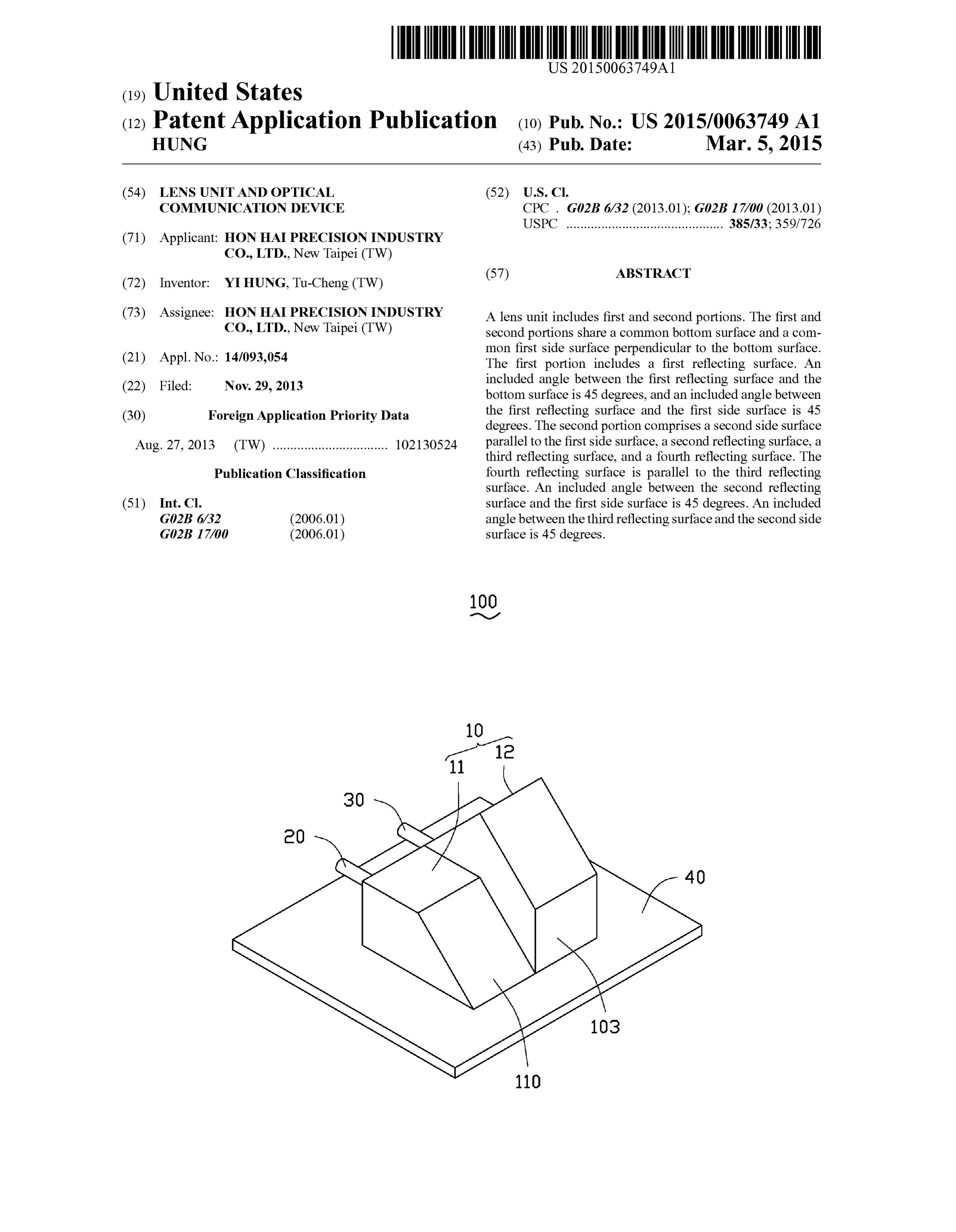
(72) Inventor: YI HUNG, Tu-Cheng (TW) (73) Assignee: HON HAI PRECISION INDUSTRY A lens unit includes first and second portions. The first and CO.,LTD., New Taipei (TW) second portions share a common bottom Surface and a com (21) Appl. No.: 14/093,054 mon first side Surface perpendicular to the bottom surface. The first portion includes a first reflecting surface. An (22) Filed: Nov. 29, 2013 included angle between the first reflecting surface and the bottom Surface is 45 degrees, and an included angle between (30) Foreign Application Priority Data the first reflecting surface and the first side surface is 45 degrees. The second portion comprises a second side Surface
Aug. 27, 2013 (TW) ................................. 102130524 parallel to the first side Surface, a second reflecting Surface, a third reflecting surface, and a fourth reflecting surface. The
Publication Classification fourth reflecting surface is parallel to the third reflecting Surface. An included angle between the second reflecting (51) Int. Cl. surface and the first side surface is 45 degrees. An included GO2B 6/32 (2006.01) angle between the third reflecting surface and the second side GO2B I7/00 (2006.01) Surface is 45 degrees.
Page 2
Drawing sheet — no readable text.
Page 3
Drawing sheet — no readable text.
Page 4
Drawing sheet — no readable text.
Page 5
Drawing sheet — no readable text.
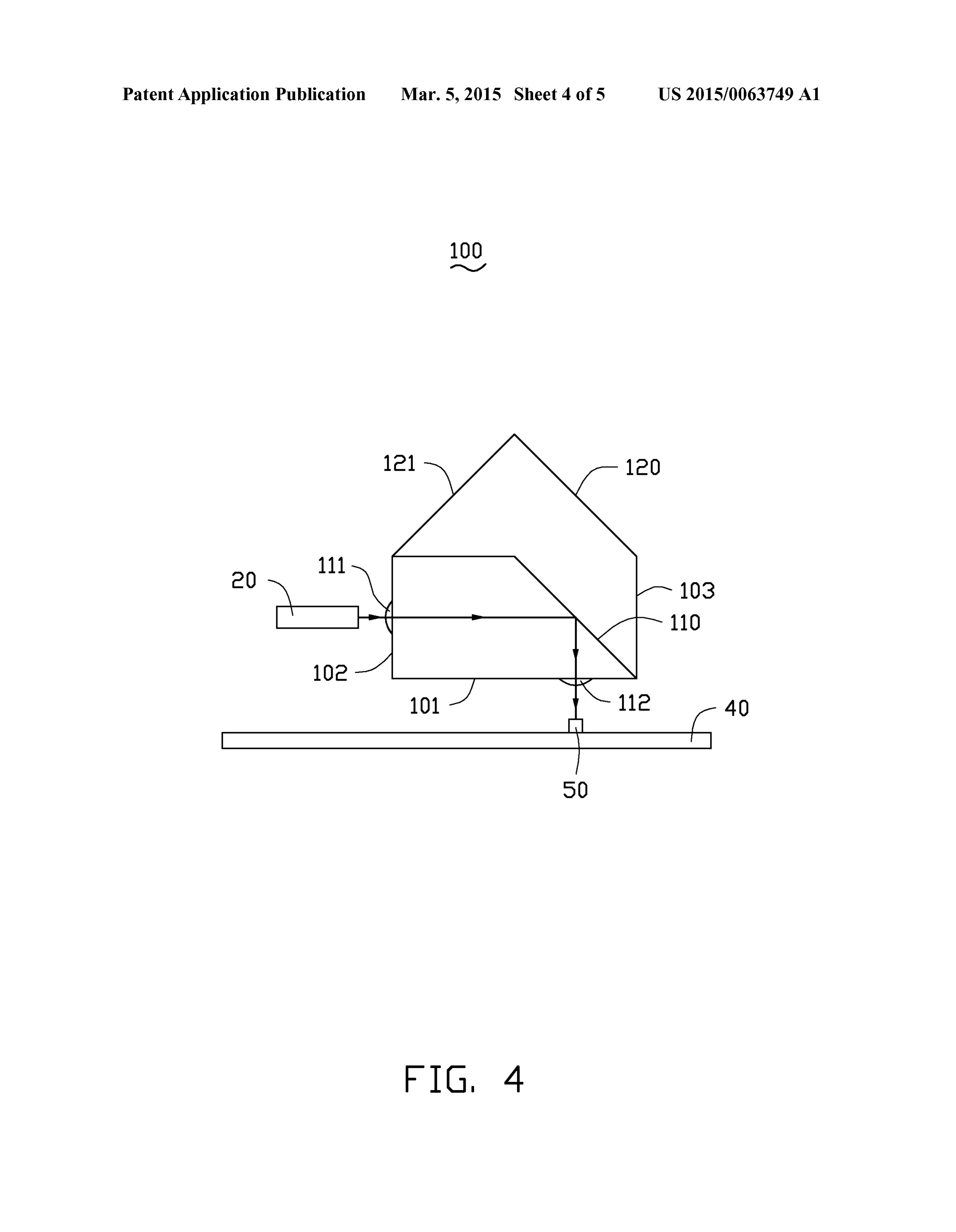
Page 6
Drawing sheet — no readable text.
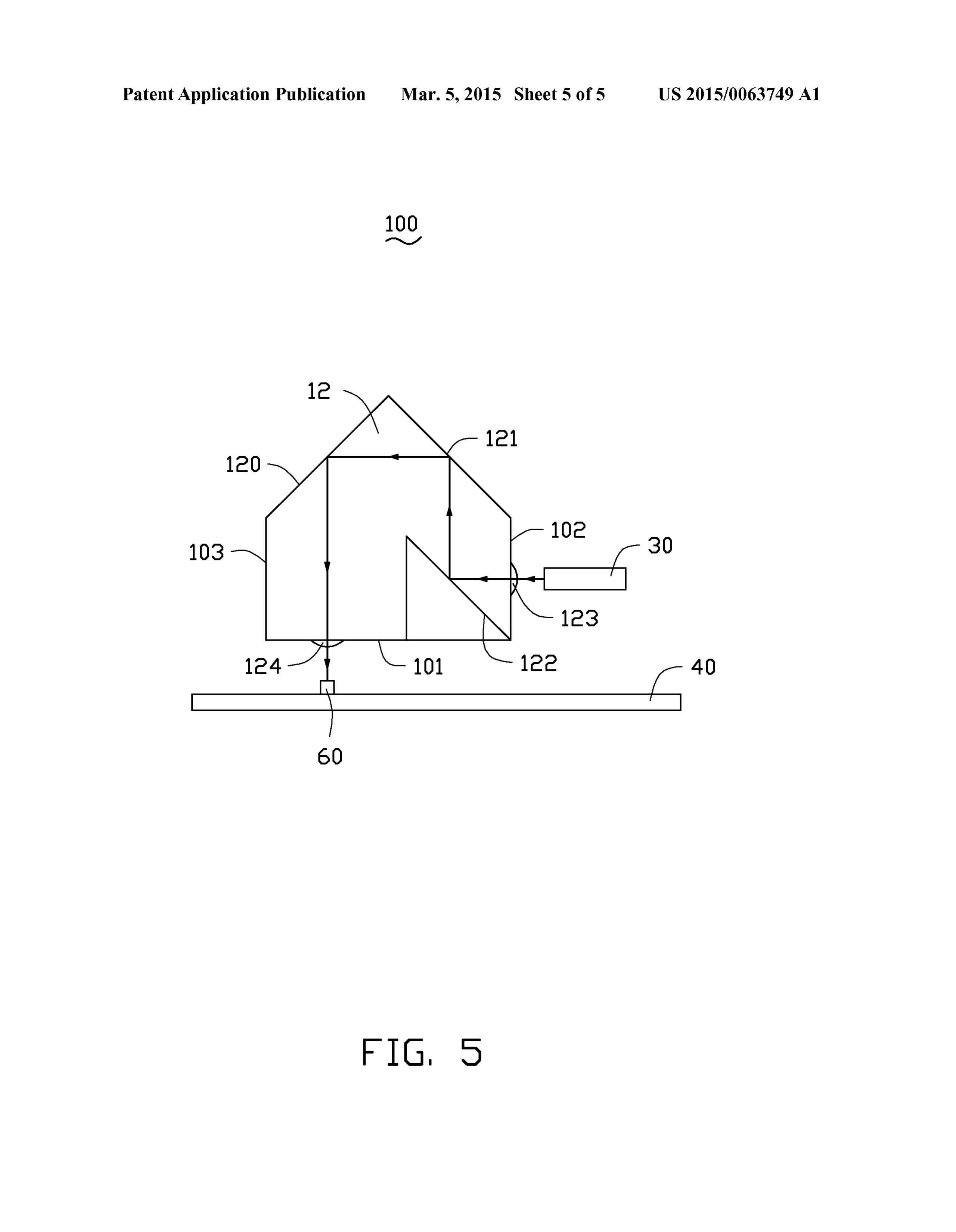
Page 7
US 2015/OO63749 A1 Mar. 5, 2015
LENS UNIT AND OPTICAL the first photoelectric unit 50, and the second optical fiber 30 COMMUNICATION DEVICE to the second photoelectric unit 60.
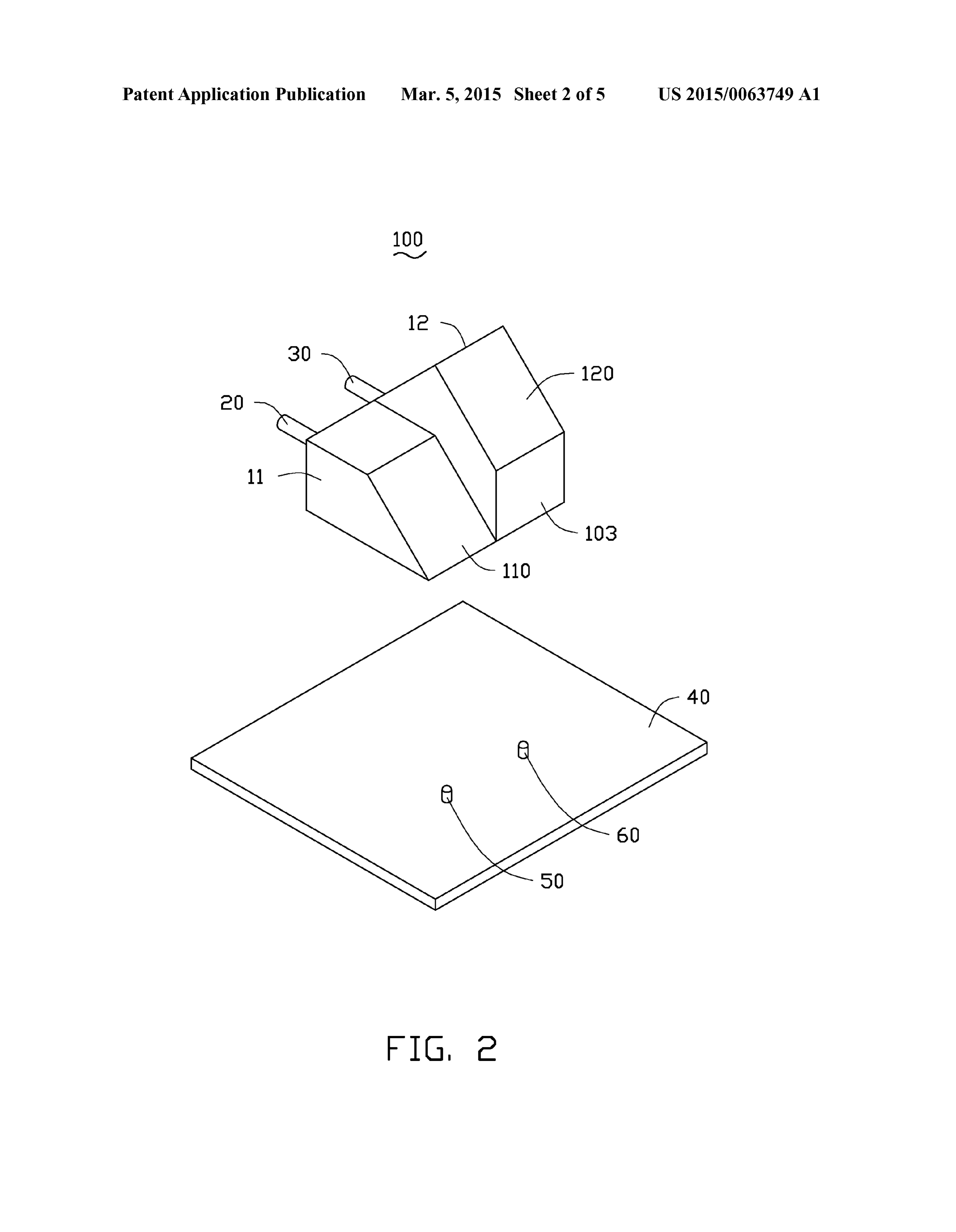
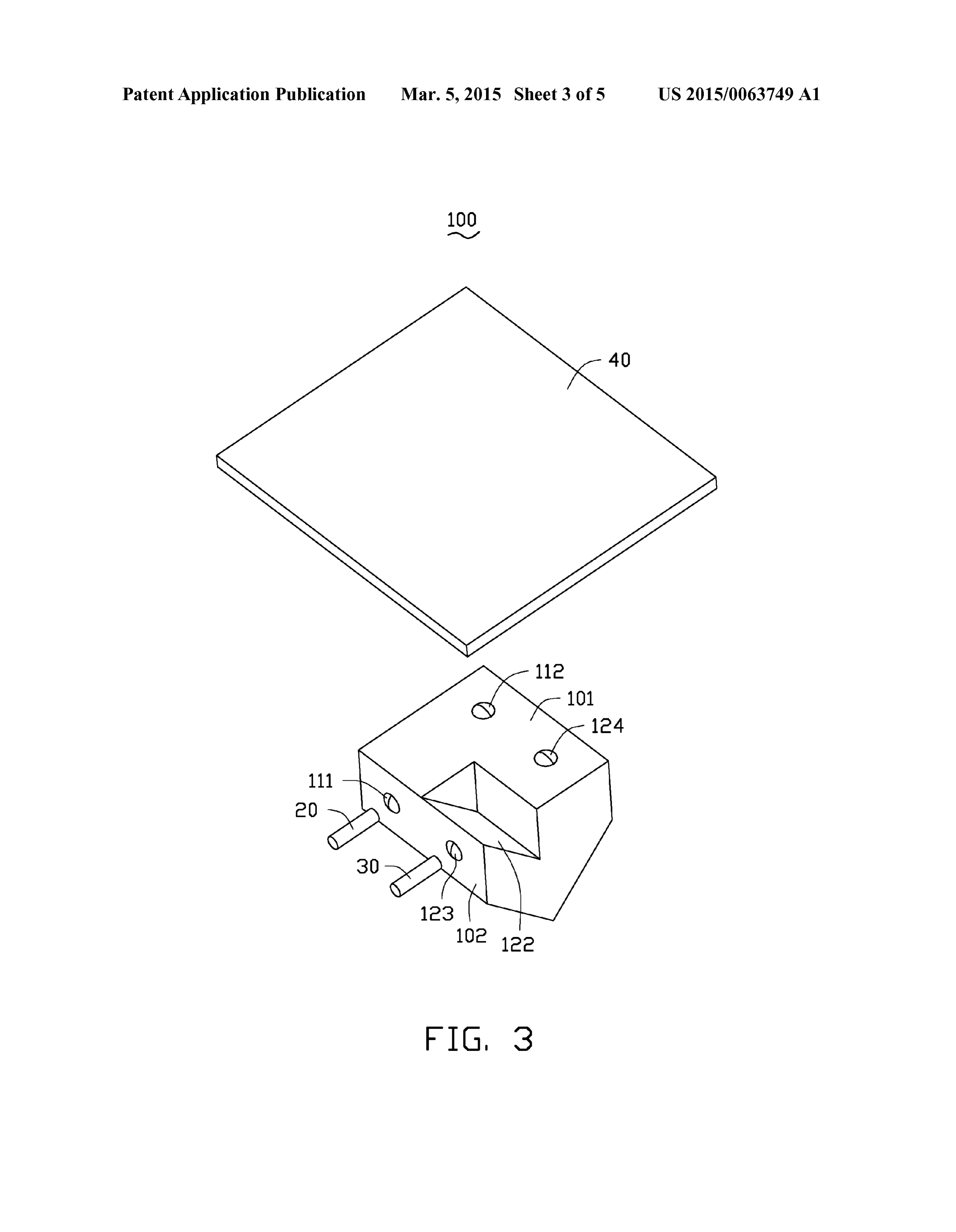
0015 The lens unit 10 includes a first portion 11 and a
BACKGROUND second portion 12. The first portion 11 is configured for 0001 1. Technical Field coupling the first optical fiber 20 to the first photoelectric unit 0002 The present disclosure relates to a lens unit and an 50. The second potion 12 is configured for coupling the sec optical communication device having the lens unit. ond optical fiber 30 to the second photoelectric unit 60. 0003 2. Description of Related Art (0016 Referring to FIGS. 4 and 5, the first portion 11 and 0004 Optical communication devices include optical the second portion 12 share a common bottom surface 101 fibers, light-emitting units, a lens unit, and light-receiving and a common first side surface 102. The first side surface 102 units. The lens unit is configured for coupling the optical is substantially perpendicular to the bottom surface 101. The fibers to the light-emitting units and the light-receiving units first side surface 102 defines a first lens 111 and a third lens 0005 Light emitted by the light-emitting units travels a 123. An optical axis of the first lens 111 is substantially certain distance in the lens unit before being coupled to the parallel to an optical axis of the third lens 123 and substan optical fibers. Light emitted by the optical fibers travels the tially perpendicular to the first side surface 102. The bottom same distance in the lens unit before being coupled to the surface 101 defines a second lens 112 and a fourth lens 124. light-receiving units. Thus, the lens unit only allows the light An optical axis of the second lens 112 is substantially parallel to travel a same distance when it is emitted and received. to an optical axis of the fourth lens 124 and substantially When the optical communication device needs light to travel perpendicular to the bottom surface 101. The first lens 111 different distances in the lens unit, two or more lens units are and the second lens 112 are located on the first portion 11. The needed, thereby increasing a size of the optical communica third lens 123 and the fourth lens 124 are located on the tion device. second portion 12.
0006. Therefore, it is desirable to provide a lens unit and 0017. The first portion 11 also includes a first reflecting an optical communication device which can overcome the surface 110. An included angle between the first reflecting limitation described. surface 110 and the bottom surface 101 is about 45 degrees. An included angle between the first reflecting surface 110 and
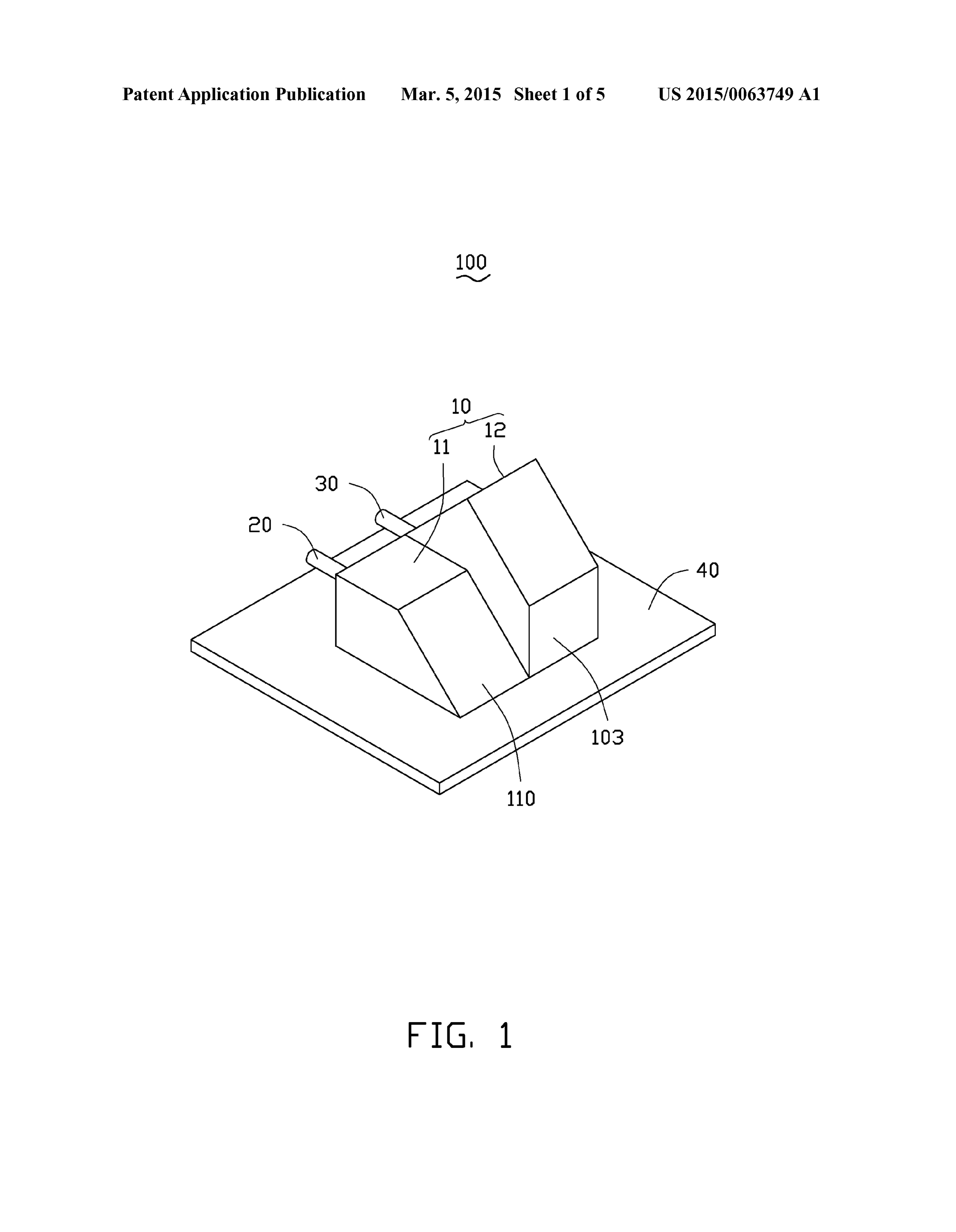
BRIEF DESCRIPTION OF THE DRAWINGS the first side surface 102 is also about 45 degrees. 0007. The components of the drawings are not necessarily 0018. The second portion 12 also includes a second side drawn to scale, the emphasis instead being placed upon surface 103, a second reflecting surface 120, a third reflecting clearly illustrating the principles of the embodiments of the surface 121, and a fourth reflecting surface 122. The second present disclosure. Moreover, in the drawings, like reference side surface 103 is substantially parallel to the first side sur numerals designate corresponding parts throughout several face 102. The second reflecting surface 120, the third reflect views. ing surface 121, and the fourth reflecting surface 122 are between the first side surface 102 and the second side surface 0008 FIG. 1 is a schematic view of an embodiment of an 103. The second reflecting surface 120 is substantially per optical communication device. pendicular and connects to the third reflecting surface 121. An 0009 FIG. 2 is an exploded view of the optical communi included angle between the second reflecting surface 120 and cation device of FIG. 1.
0010 FIG. 3 is another exploded view of the optical com the second side surface 103 is 135 degrees. The fourth reflect munication device of FIG. 1.
ing surface 122 is substantially parallel to the third reflecting surface 121. An included angel between the third reflecting 0011 FIG. 4 is a front side view of the optical communi surface 121 and the first side surface 102 is 135 degrees. The cation device of FIG. 2. fourth reflecting surface 122 extends obliquely from the bot 0012 FIG. 5 is a back side view of the optical communi tom surface 101 toward an inner middle space of the lens unit cation device of FIG. 2. 10. An included angle between the fourth reflecting surface
DETAILED DESCRIPTION
122 and the bottom surface 101 is about 45 degrees.
(0019 Referring to FIG.4, light emitted by the first optical 0013 FIGS. 1-3 show an exemplary embodiment of an fiber 20 emits onto the first reflecting surface 110 of the first optical communication device 100. The optical communica portion 11 through the first lens 111 of the first side surface tion device 100 includes a lens unit 10, a first optical fiber 20, 102. After the light is reflected by the first reflecting surface a second optical fiber 30, a circuit board 40, a first photoelec 110, the light exits from the first portion 11 through the tric unit 50, and a second photoelectric unit 60. second lens 112. The first photoelectric unit 50 receives the 0014. The circuit board 20 can be a hard circuit board or a light.
flexible circuit board. The first photoelectric unit 50 and the (0020 Referring to FIG. 5, light emitted by the second second photoelectric unit 60 are located on and electrically optical fiber 30 emits onto the fourth reflecting surface 122 of connected to the circuit board 20. In this embodiment, both the second portion 12 through the third lens 123 of the first the first photoelectric unit 50 and the second photoelectric side surface 102. The light is reflected onto the third reflecting unit 60 are light-emitting units. In other embodiment, both the surface 121. The light is then reflected onto the second reflect first photoelectric unit 50 and the second photoelectric unit 60 ing surface 120, and subsequently reflected off the second are light-receiving units. In another embodiment, one of the reflecting surface 120 to exit from the second portion 12 first photoelectric unit 50 and the second photoelectric unit 60 through the fourth lens 124. The second photoelectric unit 60 is a light-emitting unit and the other one is a light-receiving receives the light.
unit. The light-emitting unit can be a light-emitting diode or a (0021 Light emitted by the first optical fiber 20 is reflected laser diode. The light-receiving unit is a photodiode. The lens one time in the first portion 11 and is received by the first unit 20 is configured for coupling the first optical fiber 20 to photoelectric unit 50, but light emitted by the second optical
Page 8
US 2015/OO63749 A1 Mar. 5, 2015
fiber 30 is reflected three times in the second portion 12 and is of the second reflecting surface, the third reflecting surface, received by the second photoelectric unit 60. Thus, light and the fourth reflecting surface cooperatively bent a light 90 emitted by the first optical fiber 20 and the second optical fiber degrees.
30 have different optical lengths. 2. The lens unit of claim 1, wherein each of the bottom 0022. In other embodiments, both the first photoelectric Surface and the first side Surface comprises a lens. unit 50 and the second photoelectric unit 60 are light-emitting 3. An optical communication device, comprising a lens units. Light emitted by the first photoelectric unit 50 is emit unit, an optical fiber, and a photoelectric unit, the lens unit ted onto the first reflecting surface 110 through the second being configured for coupling the optical fiber to photoelec lens 112. The light is reflected by the first reflecting surface tric unit, wherein the lens unit comprises a first portion and a 110 onto the first lens 111 to enter the first optical fiber 20. second portion, the first portion and the second portion com Light emitted by the second photoelectric unit 60 enters the prises a common bottom Surface and a common first side second portion 12 through the fourth lens 124. The light is surface perpendicular with the bottom surface, the first por reflected by the second reflecting surface 120, the third tion comprises a first reflecting Surface, an included angle reflecting surface 121, and the fourth reflecting surface 122 between the first reflecting surface and the bottom surface is through the third lens 123 and onto the second optical fiber 45 degrees, an included angle between the first reflecting 3O. Surface and the first side Surface is 45 degrees, the second 0023. It is believed that the present embodiments and their portion comprises a second side Surface parallel to the first advantages will be understood from the foregoing descrip side Surface, a second reflecting Surface, a third reflecting tion, and it will be apparent that various changes may be made Surface, and a fourth reflecting Surface, the third reflecting thereto without departing from the spirit and scope of the Surface is perpendicular with the second reflecting Surface disclosure or sacrificing all of its material advantages, the and the fourth reflecting surface is parallel to the third reflect examples hereinbefore described merely being exemplary ing Surface, an included angle between the second reflecting embodiments of the disclosure. Surface and the first side Surface is 45 degrees, an included What is claimed is: angle between the third reflecting surface and the second side 1. A lens unit, comprising a first portion and a second Surface is 45 degrees, all of the second reflecting Surface, the portion connected with the first portion, wherein the first third reflecting surface, and the fourth reflecting surface portion and the second portion comprises a common bottom cooperatively bent a light 90 degrees. Surface and a common first side Surface perpendicular with 4. The optical communication device of claim 3, compris the bottom surface, the first portion comprises a first reflect ing a circuitboard, the photoelectric unit being located on and ing Surface, an included angle between the first reflecting electrically connected to the circuit board. Surface and the bottom Surface is 45 degrees, an included 5. The optical communication device of claim 4, wherein angle between the first reflecting surface and the first side the circuitboard is selected from the group consisting of hard Surface is 45 degrees, the second portion comprises a second circuit board and flexible circuit board. side surface parallel to the first side surface, a second reflect 6. The optical communication device of claim 3, wherein ing Surface, a third reflecting Surface, and a fourth reflecting the photoelectric unit is selected from the group consisting of surface, the third reflecting surface is perpendicular with the a light-emitting unit and a light-receiving unit. second reflecting Surface and the fourth reflecting Surface is parallel to the third reflecting Surface, an included angle 7. The optical communication device of claim 3, wherein between the second reflecting Surface and the second side each of the bottom surface and the first side surface comprises a lens.
surface is 135 degrees, an included angle between the third reflecting surface and the first side surface is 135 degrees, all
Provenance
- Collection
- Patents citing this work
- Original assignee
- Hon Hai Precision Industry Co Ltd
- Pages
- 8
- Method
- pdftotext (the PDF's own text layer) + pdftoppm 300dpi page scans
- Patent office record
- patents.google.com →
- Source
- Google Patents citing-documents table
- Inventors
- Yi Hung; Hon Hai Precision Industry Co Ltd
- Published
- 2015-03-05
- Transcribed from
- patentimages.storage.googleapis.com →