patent · US6328556
Gas burner for stove
11 December 2001
Page 1 — bibliographic record
(12) United States Patent (10) Patent No.: US 6,328,556 B1 Somer (45) Date of Patent: Dec. 11, 2001
(54) GAS BURNER FOR STOVE 19744564 1/1999 (DE).
(75) Inventor: Heinz Sömer, Lennestadt (DE) O 525 299 2/1993 (EP). 0751352 * 1/1997 (EP) ..................................... 431/266 (73) Assignee: Isphording Germany GmbH, O964. 203 12/1999 (EP). Attendorn (DE) 0964203 * 12/1999 (EP) ................................... 126/39 E
(*) Notice: Subject to any disclaimer, the term of this * cited by examiner patent is extended or adjusted under 35
U.S.C. 154(b) by 0 days. Primary Examiner-Carl D. Price (74) Attorney, Agent, or Firm-Herbert Dubno; Andrew
Wilford
(30) Foreign Application Priority Data A cooktop panel having a throughgoing main mounting hole and upper and lower faces has a burner having a holder
Jul. 8, 1999 (DE) .............................................. 19931 686 underneath the panel, engaging the lower face at the hole, and provided with a gas inlet and a gas nozzle and a burner (51) Int. Cl. .............................. F23D 14/06; F24C 3/08; head mainly above the panel, engaging the upper face at the F24C 3/10 hole, and forming a downwardly extending intake passage (52) U.S. Cl. ......................... 431/266; 431/354; 126/39 E into which the nozzle can feed gas. FastenerS engaged (58) Field of Search .................................. 126/38, 40, 50, through the panel between the holder and the head retain the 126/52, 214 R, 212, 214 A, 214 C, 215, holder and head against the respective lower and upper 216, 39 E; 431/354, 266 faces. A burner cover atop the burner head forms therewith an annular gas-distribution chamber comunicating with the (56) References Cited passage and forms with the burner head an annular array of
projecting rack-centering collar defining a central Seat. A 1,030,118 6/1912 O'Neil ................................... 126/52 rack atop the cover is formed centrally with a centering pin 1,291.314 9/1919 Welsenaar .............................. 126/52 engaged in the seat. The holder is formed with a radially 2,402.997 7/1946 Grayson ................................. 126/52 projecting mounting arm in turn formed with at least one 2,960,157 11/1960 Dolby. Vertically through-going igniter hole. An igniter engaged in 3.289,731 12/1966 Geber. the igniter hole projects through the panel to immediately 5,125,390 6/1992 Riehl .................................... 12/39 H 5,133,334 7/1992 Riehl. adjacent the array of outlet openings. The main mounting 5,393,224 2/1995 Allen et al. .......................... 431/266 hole is of a predetermined large diameter or a predetermined 5,443,380 8/1995 Riehl. small diameter. The holder is formed with an upwardly 5,911,572 6/1999 Williams. extending collar fitting in the hole and having a lower 5,924,860 * 7/1999 Massey et al........................ 431/266 large-diameter Step corresponding to the predetermined 6,030,207 2/2000 Salari ................................... 431/354 large diameter and an upper Small-diameter Step correspond FOREIGN PATENT DOCUMENTS ing to the predetermined Small diameter. 70 21709 3/1971 (DE). 14 Claims, 5 Drawing Sheets
Page 2
Drawing sheet — no readable text.
Page 3
Drawing sheet — no readable text.
Page 4
Drawing sheet — no readable text.
Page 5
Drawing sheet — no readable text.
Page 6
Drawing sheet — no readable text.
Page 7
GAS BURNER FOR STOVE Yet another object is to provide a burner construction that allows a cooking utensil to be set atop more than one burner,
FIELD OF THE INVENTION even if the burners are of different capacities. The present invention relates to a gas burner. More SUMMARY OF THE INVENTION particularly this invention concerns Such a burner used on a commercial- or household-duty gas Stove. A cooktop panel having a throughgoing main mounting BACKGROUND OF THE INVENTION hole and upper and lower faces has a burner having accord ing to the invention a holder underneath the panel, engaging
A Standard gas Stove has an upper cooktop panel that is the lower face at the hole, and provided with a gas inlet and formed either of sheet metal or ceramic and that is provided a gas nozzle and a burner head mainly above the panel, with a plurality of burners. Each burner comprises a burner engaging the upper face at the hole, and forming a down holder that is mounted underneath the cooktop panel and Wardly extending intake passage into which the nozzle can that is provided with a nozzle connected to a Source of feed gas. FastenerS engaged through the panel between the propane or butane, a burner head that is mainly above the holder and the head retain the holder and head against the cooktop panel and that diverts the gas from the nozzle 15 respective lower and upper faces. A burner cover atop the normally into an annular array of jets, and a rack that fits burner head forms there with an annular gas-distribution over the head and that is intended to Support a cooking chamber communicating with the passage and forms with utensil. A Spark-type electrical igniter is also normally the burner head an annular array of outlet openings. In provided at each burner. accordance with the invention this cover is formed with an The rack normally is fitted with formations made in the upwardly projecting rack-centering collar defining a central cooktop panel. When the panel is made of sheet metal, it is Seat. A rack atop the cover is for centrally with a centering relatively easy to provide appropriate Seats for centering pin engaged in the Seat.
fingers on the rack, but when the panel is of ceramic, which Thus the rack according to the invention is centered on the is much more difficult to shape and machine, Such centering 25 burner bead. No formations need be made in the cooktop, formations are more difficult or impossible to provide. Thus and the centering formation can be a simple pin which the rack can slide about or be quite difficult to position makes fitting the rack in place, for instance after cleaning, a accurately. very simple and intuitive operation. In addition the overall thickness of the cooktop panel The burner further has according to the invention a cover varies considerably. When made of enameled steel it is quite plate fitting complementarily atop the burner cover and thin, and when made of ceramic it is much thicker. In formed with a central hole exposing the Seat. This plate can addition due to the difficulty of forming mounting holes in be decorative.
ceramic, the hole in the panel through which the burner extends is normally made larger in ceramic So that Screws is According to another feature of the invention the holder formed with a radially projecting mounting arm in turn
Securing the head to the holder can pass through it, while 35 formed with a metal panel it is easy to form Separate holes for the hole. An with at least one vertically throughgoing igniter mounting Screws. it is therefore necessary to provide dif the paneligniter engaged in the igniter hole projects through to immediately adjacent the array of outlet open ferent burner constructions to accommodate the different panel thicknesses as well as the different layout of the ings. The length of the arm of the holder is enough to accommodate burners of different diameters and more than mounting Screws. 40 one hole can be formed in it. Thus the same holder can be The burners typically vary in size, mainly in diameter. A used for burners of different size.
large burner can in principle have, however, the same The igniter hole according to the invention is provided Support as a Small burner and merely needs a larger head and nozzle of greater flow croSS Section. Due to the larger head, with a liner sleeve. In addition the panel is formed offset it is necessary to provide the igniter at a different spacing 45 from the main mounting hole with a Supplemental hole from the center and, Since the igniter is mounted on the igniter aligned with the igniter hole and holding the igniter with the holder, it has to be spaced differently from the center of the radiallyhole. The burner head can also be provided with a holder for burners of different sizes. Thus using the same ing hole projecting arm formed with a vertically throughgo aligned with the Supplemental hole and ignitor hole holder is normally impossible and it is necessary to provide a separate holder for each burner size. 50 and holding the igniter therewith.
With many Standard Systems, large burners are Somewhat In accordance with another feature of the invention the taller than Small burners. Thus a pot sits Somewhat higher on main mounting hole is of a predetermined large diameter or a taller burner. This not only creates a nonuniform and a predetermined small diameter. The holder is formed with unattractive appearance, but makes it impossible to Set a an upwardly extending collar fitting in the hole and having cooking utensil, for instance a large kettle, on two adjacent 55 a lower large-diameter Step corresponding to the predeter burners of different size. mined large diameter and an upper Small-diameter Step corresponding to the predetermined Small diameter.
OBJECTS OF THE INVENTION Thus with this system the same holder can be used for It is therefore an object of the present invention to provide thick ceramic panels or thin metal panels. Normally the thick an improved gas burner for a Stove. 60 ceramic panels have a large hole So that the fastening Screws Another object is the provision of Such an improved gas can engage through them. The metal panels with the Smaller burner for a stove which overcomes the above-given mounting hole have Separate holes through which the disadvantages, which is, for example, of basically Standard mounting Screws extend.
ized construction So that most of its parts can be used both The Steps according to the invention are cylindrical and in Small and large burners. 65 coaxial. The mounting holes are usually circular. A further object is to provide such a burner which can be According to another feature of the invention the holder used both with sheet-metal and ceramic cooktops. is formed with a radially outwardly open groove and the
Page 8
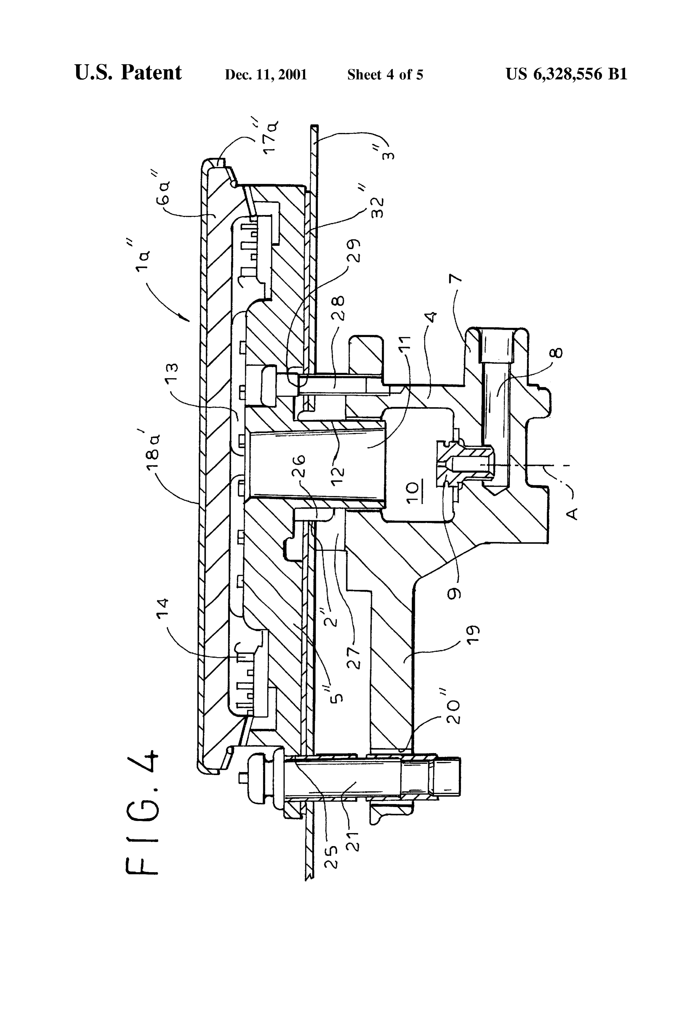
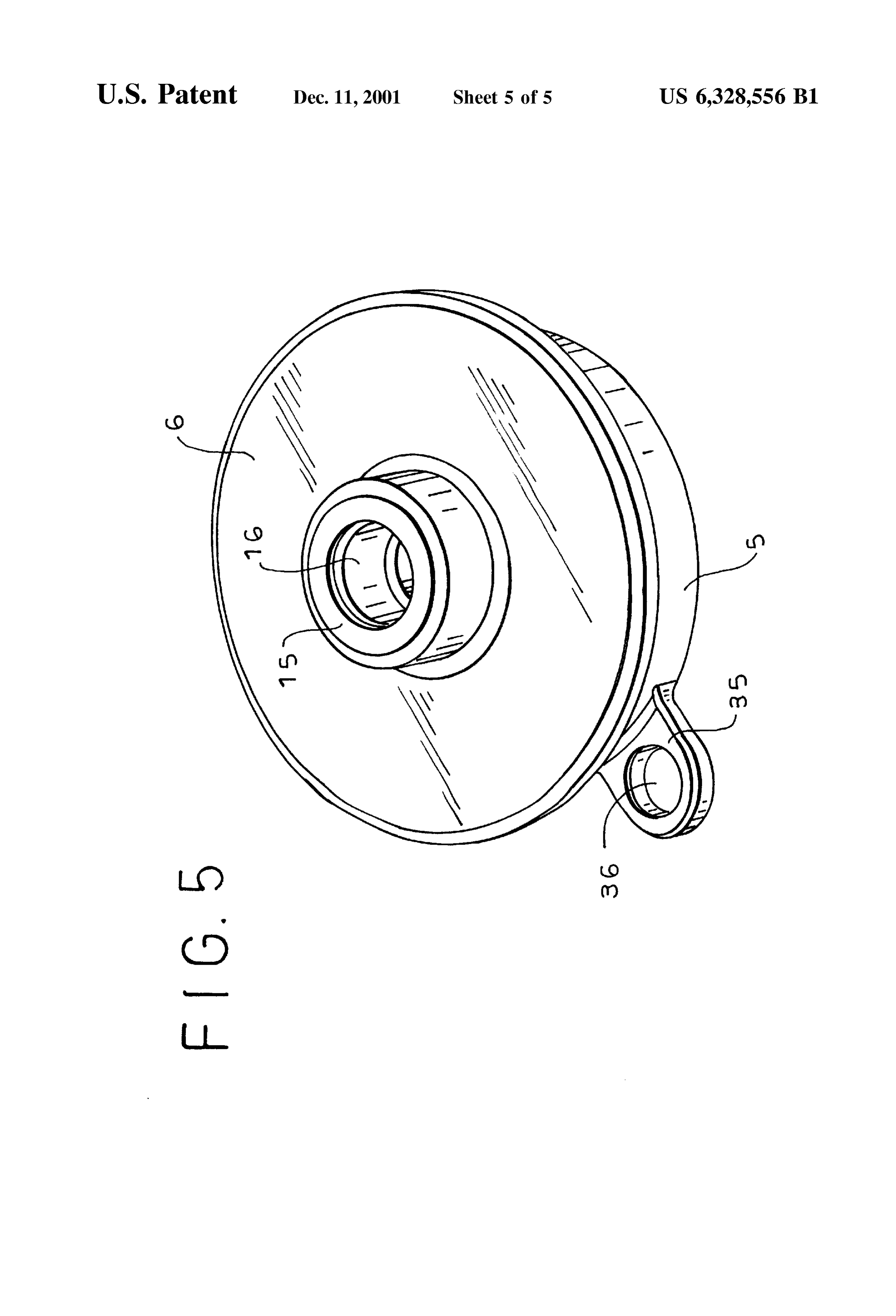
burner cover is formed with a radially outwardly projecting that is closer to the axis A is used and for a larger burner as ridge engaged in the groove. This structure ensures that in FIGS. 2 and 4, the outer hole 20" is used. Whichever hole these two parts fit together in the desired angular orientation, 20" or 20" is used, it is provided with a retaining sleeve 22 which is particularly important for aligning the ignitor with for the igniter 21. In addition the panel 3', 3" is formed in its mounting holes in the panel and head. line with whichever hole 20' or 20" is used with a hole 25 The gas-flow passage is constricted as a venturi and provided with another liner sleeve 25a. Furthermore the normally Sucks in air to aid combustion. In addition nor head 5", 5" is formed with a radially outwardly projecting mally the cooktop is formed with a plurality of Such mount flange or arm 35 formed with a vertically throughgoing hole ing holes each provided with a respective holder, burner 36 (see also FIG. 5) in line with the respective holes 20, 20" head, means, and burner cover. The burner coverS all having and 25. The cover 6, 6' can also he provided with a radially upper Surfaces spaced a predetermined identical distance extending arm provided with a hole for the igniter 21 to aid from the upper panel face. Thus the burners, whether big or alignment of this part. The igniter 21 is installed from above, Small, have an attractive uniform appearance and a cooking So it can easily be repaired or replaced without dismantling utensil can be set Stably atop two burners. the stove.
15 The head 5", 5" is formed with a radially outwardly
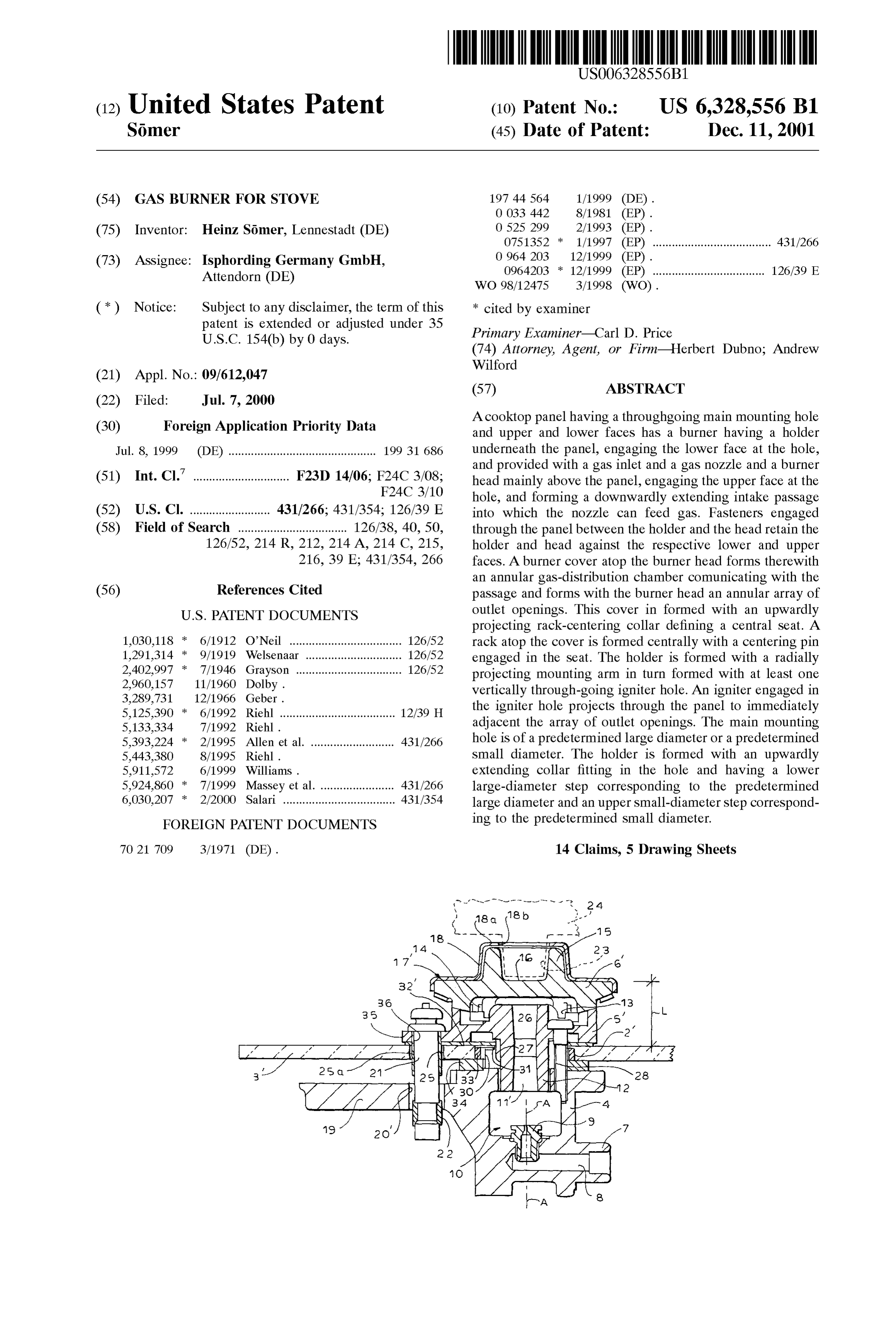
BRIEF DESCRIPTION OF THE DRAWING projecting and axially extending rib 26 that fits in a comple The above and other objects, features, and advantages will mentary groove 27 of the holder 4 to angularly position the become more readily apparent from the following head 5", 5" on the holder 4. The holder 4 is formed with a description, reference being made to the accomanying draw collar having lower and upper steps 30 and 31 respectively ing in which: of large and Small diameter. The large-diameter lower Step 30 is adapted to fit in the large-diameter hole 2" formed in the
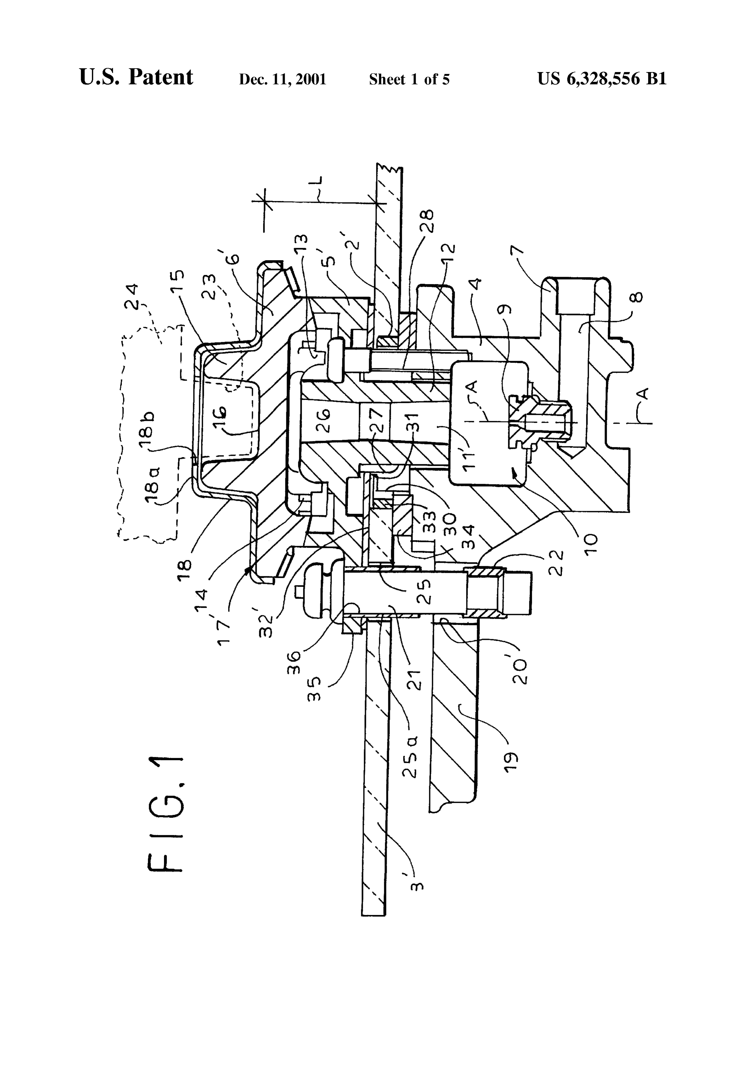
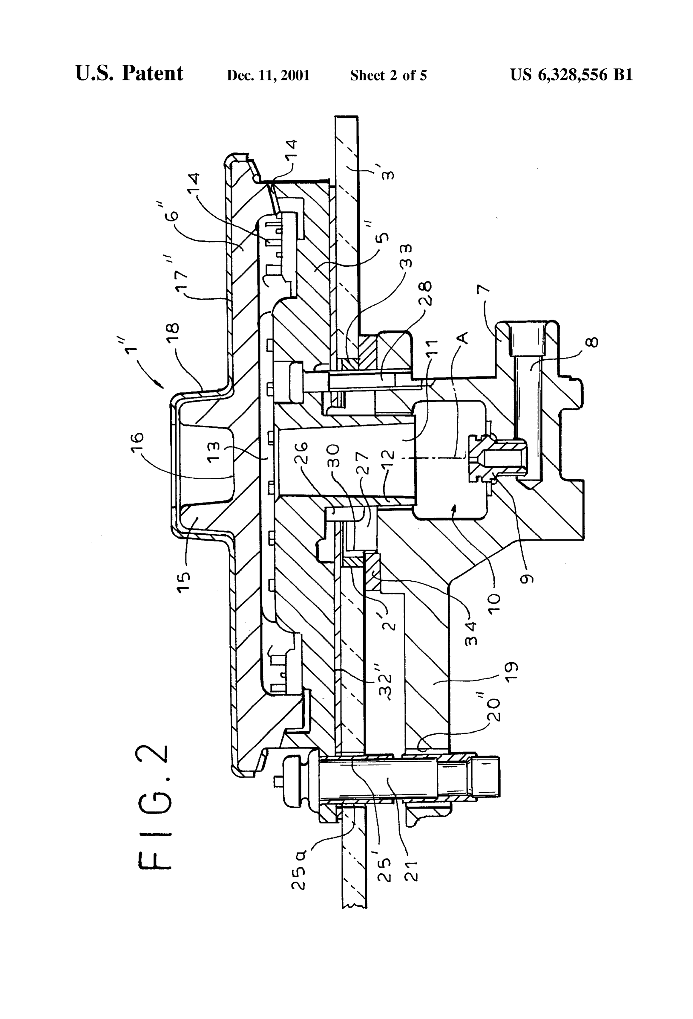
FIGS. 1 and 2 are vertical sections through a burner etrmic cooktop 3' which is made large enough to accom according to the invention in two different sizes, modate axially extending Screws 28 whose heads bear FIGS. 3 and 4 are views like FIG. 1 of another burner in downward on the head 4' and whose shanks are threaded into accordance with the invention; and 25 the holder 4. The small-diameter upper step 31 is dimen FIG. 5 is perspective view of the burner of FIG. 2. Sioned to fit in the Small-diameter hole 2" formed in a metal
SPECIFICDESCRIPTION
cooktop 3", which is formed with separate holes 29 for the
Screws 28. A large-diameter sheet washer or cushion sheet
AS seen in FIGS. 1, 2, 3, and 4 a burner 1", 1", 1a', or 1a" 32", 32" is provided between the lower face of the head 5', according to the invention extends through a hole 2" or 2", 5" and the upper face of the cooktop 3", 3", another such in a thick ceramic cooktop panel 3' (FIGS. 1 and 2) or a washer 34 is provided between the upper face of the holder thinner steel cooktop panel 3" (FIGS. 3 and 4), having a 4 and the lower face of the ceramic cooktop 3", and a further cast-metal burner holder 4 of standardized design below the lining sleeve 33 is provided between the inner edge of the cooktop 3' or 3" and a small or large burner head 5' or 5" 35 hole 2 of the cooktop 3' and the holder 4, as direct above the cooktop 3' or 3". The burner head 5", 5" has a cover metal-to-ceramic contact should be avoided. The sheet 32", 6", 6", 6a', or 6a" that fits complementarily with it. 32" has holes corresponding to the main mounting hole 2" or The standardized holder 4 has an intake fitting 7 for 2" and the ignitor hole 25.
receiving cooking gas which moves through an intake All the burners 1", 1", 1a", 1a" according to the invention passage 8 to a nozzle 9 dimensioned for the type of gas and 40 ishave a height Labove the upper face of the panel 3', 3" that the same. In addition since the holder 4 and burner head burner capacity and defining a central axis. A for the burner 1 Thence the gas enters a chamber 10 formed in the holder 5", 5" are solidly screwed to each other to opposite sides of 4 and passes up through a passage 11 formed by a tube 12 the panel 3', 3", the structure is very stable and any spills on extending downwardly from the head 5", 5" into the holder the cooktop panel 3', 3" will not run down through the hole 4. From the upper end of the tube 12 the gas enters a 45 2,What 2".
is claimed is:
basically annular distribution chamber 13 in the head 5", 5" and then exits as an annular array of jets from apertures or 1. In combination with a cooktop panel having a through notches 14 formed between the head 5,5" and its cover 6', going main mounting hole and upper and lower faces, a 6", 6a' or 6a". burner comprising:
In the arrangement of FIGS. 1 and 2 the head cover 6", 6" 50 a holder underneath the panel, engaging the lower face at is formed centered on the axis. A with an upwardly projecting the hole, and provided with a gas inlet and a gas nozzle; collar 15 forming an axially centered and upwardly open a burner head mainly above the panel, engaging the upper Seat 16 adapted to receive a center pin 23 of a rack shown face at the hole, and forming a downwardly extending partially at 24 in FIG. 1. For decorative purposes, a sheet intake passage into which the nozzle can feed gas, metal cover plate 17, 17" fits over the top of the head cover 55 means engaged through the panel between the holder and 6", 6" and has a central formation 18 that fits complemen the head and retaining the holder and head against the tarily with the collar 15, having an inwardly directed lip 18a respective lower and upper faces, forming a hole 18b giving access to the Seat 16. a burner cover atop the burner head, forming there with an In FIGS. 3 and 4 the structure is identical to that of FIG. annular gas-distribution chamber communicating with 1, except that the cover 6a, 6a" has no rack-centering collar 60 the passage, forming with the burner head an annular 15 and the respective cover plate 17a", 17a" has a planar top array of outlet openings centered on an axis, and wall 18a, 18a'. formed at the axis with an upwardly projecting rack In both systems the holder 4 is formed with a radially centering collar defining an axially upwardly open projecting flange or arm 19 formed with a plurality of central Seat; and vertically throughgoing holes 20, 20' adapted to hold an 65 a rack atop the cover and formed centrally with an axially igniter 21 of the Standard Spark type that is inserted from downwardly directed centering pin engaged in the Seat, above. For a small burner as in FIGS. 1 and 3, the hole 20' the rack being Separable from the cover.
Page 9
S 6 2. The burner defined in claim 1, further comprising a burner head mainly above the panel, engaging the upper a cover plate fitting complementarily atop the burner face at the hole, and forming a downwardly extending cover and formed with a central hole exposing the Seat. intake passage into which the nozzle can feed gas, 3. In combination with a cooktop panel having a through means engaged through the panel between the holder and going main mounting hole and upper and lower faces, a the head and retaining the holder and head against the burner comprising: respective lower and upper faces, and a holder underneath the panel, engaging the lower face at a burner cover atop the burner head, forming there with an the hole, provided with a gas inlet and a gas nozzle, and annular gas-distribution chamber communicating with formed with a radially projecting mounting arm extend 1O the passage, and forming with the burner head an ing underneath the panel and formed with at least one annular array of outlet openings. Vertically throughgoing igniter hole;
a burner head mainly above the panel, engaging the upper cylindrical The burner defined in claim 8 wherein the steps are and coaxial.
face at the hole, and forming a downwardly extending 10. The burner defined in claim 8 wherein the means intake passage into which the nozzle can feed gas, 15 includes Screws engaged through the main mounting hole in means engaged through the panel between the holder and the case same is of the predetermined large diameter. the head and retaining the holder and head against the 11. The burner defined in claim 8 wherein the means respective lower and upper faces, includes Screws engaged through the panel offset from the a burner cover atop the burner head, forming there with an main mounting hole in the case is of the predetermined Small annular gas-distribution chamber communicating with diameter.
the passage, and forming with the burner head an 12. In combination with a cooktop panel having a annular array of outlet openings, and throughgoing main mounting hole and upper and lower an igniter engaged in the igniter hole and projecting faces, a burner comprising:
upward through the panel to immediately adjacent the a holder underneath the panel, engaging the lower face at
the main mounting hole and provided with a gas inlet 4. The burner defined in claim 3 wherein the igniter hole and a gas nozzle, and formed with an upwardly extend is provided with a liner sleeve.
5. The burner defined in claim 3 wherein the panel is ing collar fitting in the hole and formed with a radially formed offset from the main mounting hole with a Supple outwardly open groove;
mental hole aligned with the igniter hole and holding the a burner head mainly above the panel, engaging the upper igniter with the igniter hole. face at the hole, forming a downwardly extending 6. The burner defined in claim 5 wherein the burner head intake passage into which the nozzle can feed gas, and is provided with a radially projecting arm formed with a formed with a radially outwardly projecting ridge Vertically throughgoing hole aligned with the Supplemental engaged in the groove, whereby the ridge and groove hole and igniter hole and holding the igniter there with. 35 prevent rotation of the head on the holder; 7. The burner defined in claim 5, further comprising means engaged through the panel between the holder and a cushion sheet between the burner head and the upper the head and retaining the holder and head against the panel face and formed with a large-diameter hole respective lower and upper faces, and corresponding to the main mounting hole and a Small 40 a burner cover atop the burner head, forming there with an diameter hole aligned with the igniter hole. annular gas-distribution chamber communicating with 8. In combination with a cooktop panel having a through the passage, and forming with the burner head an going main mounting hole of a predetermined large diameter annular array of outlet openings. or a predetermined Small diameter and upper and lower 13. The burner defined in claim 12 wherein the passage is faces, a burner comprising: 45 constricted as a venturi.
a holder underneath the panel, engaging the lower face at 14. The burner defined in claim 12 wherein the cooktop is the hole, provided with a gas inlet and a gas nozzle, and formed with a plurality of Such mounting holes each pro formed with an upwardly extending collar fitting in the Vided with a respective holder, burner head, means, and hole and having a lower large-diameter Step corre burner cover, the burner covers all having upper Surfaces sponding to the predetermined large diameter and an 50 Spaced a predetermined identical distance from the upper upper Small-diameter Step corresponding to the prede panel face.
termined Small diameter, one of the Steps fitting complementarily in the hole;
Provenance
- Collection
- Cited prior art
- Original PDF
- patentimages.storage.googleapis.com →
- Filed
- 2000-07-07
- Pages
- 9
- Method
- pdftotext (the PDF's own text layer) + pdftoppm 300dpi page scans
- Source
- Google Patents bibliographic record
- Granted
- 2001-12-11
- Inventors
- Heinz S{overscore (o)}mer; Isphording Germany GmbH
- Transcribed from
- patentimages.storage.googleapis.com →