patent · US2960157
Gas burner
15 November 1960
Page 1
Drawing sheet — no readable text.
Page 2
United States Patent Office 2,960,157 Patented Nov, 15, 1960
stantially horizontal shoulder or Step 26 is formed be tween the lower and upper portions 22 and 24.
To discharge the fuel and air mixture from the shell 2,960,157 12, a multiplicity of main ports 28 are formed through
GAS BURNER the upper, small diameter portion 24. All of the ports 28 are at the same horizontal level and are spaced a
John W. Dolby, Elgin, Ill., assignor to Configured Tube short distance above the shoulder 26. The relation be Products Co., Bellwood, Ill., a corporation of Illinois tween the shoulder or offset portion 26 and the ports 28 Filed Nov. 29, 1955, Ser, No. 549,662 is such that at low turn down the shoulder forms a pock 10 et which causes the fire from the ports to merge creat 5 Claims. (Cl, 158-116) ing, in effect, a single annular port. This action results in stable operation of the burner at extremely low flow
TafCS.
A. multiplicity of Secondary ports 30 are formed in
This invention relates to burners for use with a mix 15 the larger diameter portion 22 of the outer shell 12. It ture of gaseous fuel and air and pertains particularly to will be seen that the diameter of the secondary ports is Substantially less than that of the primary or main ports burners made of sheet metal or the like,
Thus, one principal object of the invention is to pro 28. The Secondary ports 30 are spaced a short distance vide a new and improved burner which may be made 20 below the shoulder or step 26. Very economically, principally of sheet metal or other is The flow of fuel-air mixture to the secondary ports 30 controlled by a generally tubular baffle 32 mounted thin material, yet will give outstanding performance when within the outer shell 12. It will be seem that the tubu used on a cooking Stove or some other heating appli lar baf?le 32 takes the form of a three-diameter immer
A further object is to provide a burner of the fore 25 Small shell having an upper annular element 34 of relatively going character which is extremely small in size yet is diameter, diameter, a lower element 36 of relatively great capable of adequately high heat output. and an intermediate annular element 38 of in It is another object to provide a new and improved termediate diameter. A. pair of shoulders or steps 40 burner which will provide heat output over an extremely and and 42 are formed between the intermediate element 38 wide range so that the burner may be adjusted to the 30 Astheillustrated, upper and lower elements 34 and 36. the upper element 34 is of an outer $lowest Simmer or the fastest boil or to any desired heat diameter corresponding to the inner diameter of the Setting therebetween. smaller portion 24 on the outer shell {2. The element A further object is to provide a new and improved burner of the foregoing character which is arranged to 34 is Snugly received within the lower end of the portion 24 so that a gas-tight joint will be formed therebetween.
prevent the burner flame from backfiring into the burner. 35 The
It is another object to provide a new and improved side upper side of the step 46 abuts against the lower of the step or shoulder 26 so that the inner shell burner of the foregoing character which is arranged to 32 is positively located in the outer shell 12. As shown, provide an advantageous flame distribution.
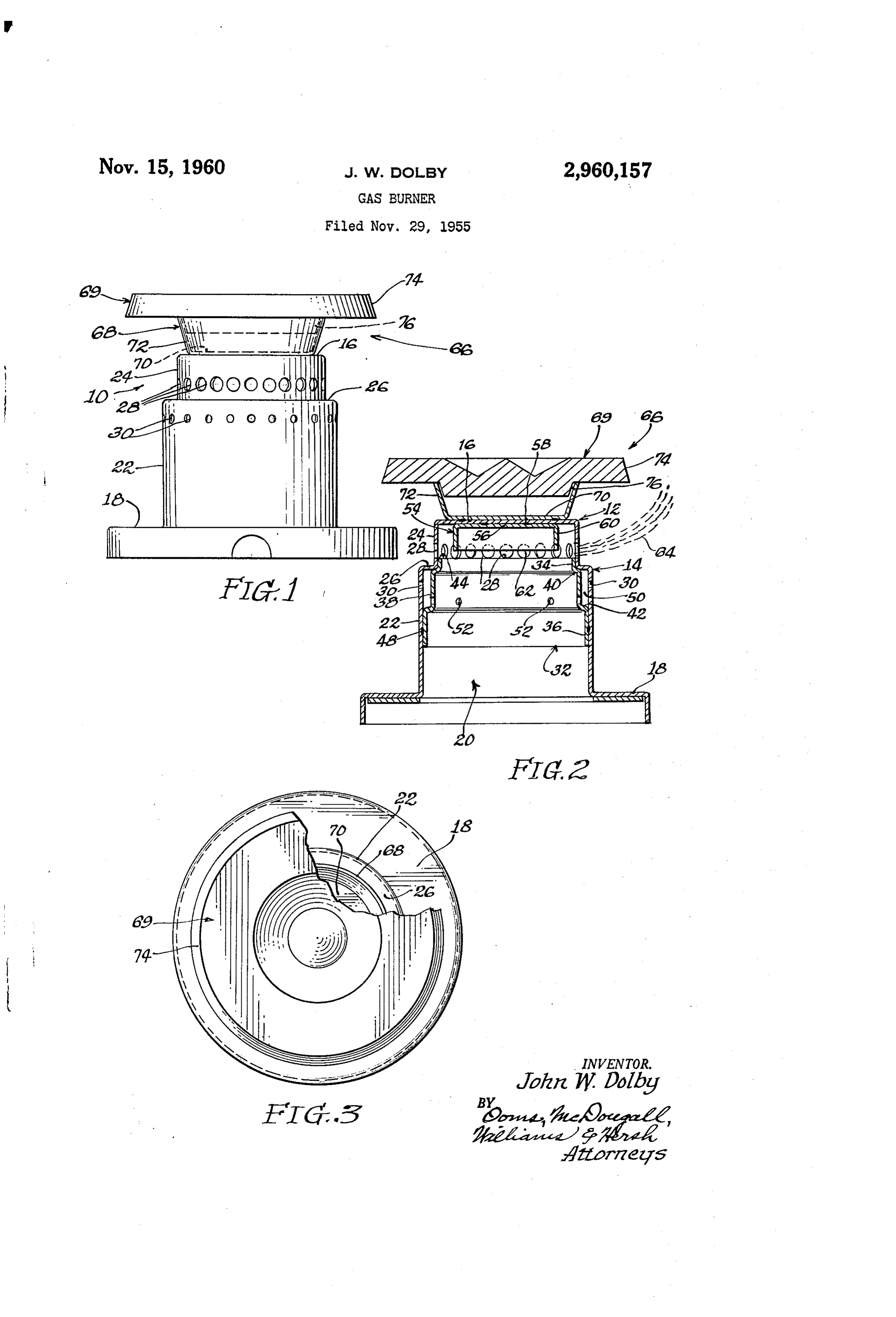
Further objects and advantages of the invention will ly the small diameter element 34 has an upper, substantial appear from the following description, taken with the 40 er horizontal annular edge 44 which is adjacent the low margins of the main ports 28. The inner shell 32 accompanying drawings, in which:
Figure 1 is an enlarged elevational view of a sheet thereby nular conveniently provides an inwardly extending an ledge at a level corresponding generally to that of metal burner constituting an illustrative embodiment of the lowermost extremities of the ports 28. The annular the present invention;
Fig. 2 is a central elevational sectional view taken 45 to ledge or edge 44, when located as shown in Fig. 2, tends through the burner of Fig. 1; and have a lowering or depressing effect on the path of Fig. 3 is a plan view of the burner of Fig. 1. the fuel-air mixture as it passes outwardly through the If the drawings are considered in greater detail, it will ports 28, so that the mixture travels outwardly at a Small be seen that they illustrate a burner 10 which is shown ledge 44. angle than it would in the absence of the er upward at about twice its actual size. It will thus be appreciated 50 The width and elevation of the ledge 44 affect the an that the burner is of extremely compact form. Neverthe leSS, the burner is capable of being adjusted continuous gle of the flame. in general, the lowering effect on the flame tends to be increased as the ledge 44 is made ly to give a heat output over an extremely wide range higher relative to the lower' extremities of the ports 28. extending, for example, between 500 and 16,000 B.t.u.’s In other words, raising the ledge increases the lowering per hour. 55
The illustrated burner is made principally of sheet met orItdepressing efect on the flame. will be seen that the large diameter lower element ai and hence may be produced at extremely low cost. 36 of the inner shell 32 corresponds in outer diameter to The small size of the burner also contributes to its eco nomical construction. Ít will be seen that the illustrated the inner diameter of the lower portion 22 on the outer shell 12. The portion 36 is snugly received within the burner 19 comprises an outer shell F2, generally of in 60 portion
Verted cup-shaped form. As shown, the outer shell 12 32 so as to form a gas-tight joint therebetween. comprises a two-diameter side wall 14 Surmounted by The inner shell 36 may be secured within the outer shell a flat horizontal top wall 16. The lower end of the shell 12 in any suitable manmer, as by spot or seam Welding, is formed into a mounting flange 18 which Surrounds an as indicated at 48 in Fig. 2.
axial opening 20 adapted to receive a mixture of fuel 65 anThe intermediate portion 38 of the inner shell 32 is of outside diameter greater than that of the smaller por and air from a suitable mixing tube or the like. The tion 34 but less than the inside diameter of the lower burner is constructed for use with all city gases, whether portion 22 on the outer shell 12. Thus, an annular space natural, manufactured or mixed, and also for use with 50 is defined between the intermediate portion 38 and liquified petroleum gases including butane and propane. the cylindrical portion 22 of the outer shell {2. A The illustrated two-diameter side wall 14 comprises a 70 plurality of metering ports 52 extend through the inter lower portion 22 of relatively large diameter and an up mediate portion per portion 24 of smaller diameter, An annular, Sub space 50. It will38betoseen admit the fuel-air mixture to the that the metering ports 52 are
Page 3
Small in size and few in number so as to restrict the flow mounted on the top of the outer shell 12. While the of mixture into the space 50. The metering ports 52 are flame spreader 66 might readily be made in one piece, at a substantially lower level than that of the secondary it is made in lower and upper parts 68 and 69 in the discharge ports 30. The arrangement of the wall por illustrated construction. It will be seen that the lower tions 22 and 38 and the ports 30 and 52 is such as to pre part 68 is made of sheet metal and is generally cup or vent backfiring through the secondary ports 30. If any disk shaped. It has a lower wall 70 which is welded or flame travels back through one of the ports 30, it will be otherwise secured to the upper wall 16 of the outer shell extinguished by the cool inner wall portion 38 and will 12. The diameter of the lower wall 70 corresponds not be propagated through the space 50 into the interior roughly but is illustrated as being slightly less than that of the shells 12 and 32. The provision of the space 5{} 10 of the wall 16. A downwardly tapering frusto-conical and the arrangement of the ports 30 and 52 stabilizes the side wall 72 extends upwardly from the lower wall 70. flames at the secondary ports 30. The flames at the In this instance, the upper part 69 of the flame Spreader secondary ports stabilize the main f?ames at the main 66 is in the form of a disk-like member having an ports 28, particularly at high rates of flow. In particu upper portion 74 which is supported on the upper edge lar, the secondary flames prevent the main flames from 15 of the side wall 72 and projects outwardly in overhang being blown away from the main ports 28. ing fashion therefrom. As illustrated, the disk-like part To direct the fuel-air mixture through the main ports 69 has a downwardly projecting lower portion 76 which 28 and prevent backfiring therethrough, the burner is is received in the upper end of the disk-shaped lower provided with an additional baffling member 54 which 20 part 68. It will be seen that the projecting lower por may assume various forms, but, as shown, is generally tion 76 is downwardly tapered in conformity with the of inverted cup-shaped form. Thus, the baffle 54 com shape of the side wall 72. As illustrated, the upper part prises a flat substantially horizontal upper wall 56 which 69 is merely retained by gravity in the lower part 68, but, is secured to the underside of the top wall 16 on the outer of course, the two parts may be suitably Welded Or shell 12. One or more spot welds 58 may be formed be 25 otherwise secured together.
tween the walls 16 and 56 to hold the baffle 54 in place. The upwardly f?aring side wall 72 and the Overhang The baffle 54 also includes an annular, substantially ing portion 74 of the disk 69 tend to spread the main cylindrical side wall or flame 60 which extends down fiames outwardly so that they will engage a large area. On wardly in depending relation to the upper wall 56. It any kettle or pot placed above the burner. will be seen that the annular side wall 60 is concentric When there is no cooking utensil over the burner, the with but spaced inwardly from the upper side wall por 30 action of the flame spreader 66 is particularly important tion 24 on the outer shell 12. The annular wall 6{} eX in controlling the upward curl of the main flames. With tends downwardly so that it will at least partly overlap a large kettle or pan over the burner, the bottom of the the main ports 28. It will be understood that the exact pan directs the flames outwardly so that they travel along level of the edge 62 may be varied to a certain extent, 35 a maximum area on the pan. Thus, the pan has a Spread with some effect upon the angle of the flames at the ing effect on the flame. In other words, the flameS tend ports 28. As illustrated in Fig. 2, the spacing between the to change in shape to adapt themselves to the Size and baf?le wall 60 and the wall 24 of the shell 12 is com shape of the pam.
parable to the size of the main ports 28, and is a mino When the burner is turned on to extremely low levels, fraction of the diameter of the baf?le. + 40 the spreader 66 spreads the heat from the flames out.
The annular baffle wall 60 substantially prevents back wardly so that the heat is directed to the outer edges of f?ring of the flames through the ports 28. If any flame the pan and is not concentrated at the center. This travels inwardly through one of the ports 28, it will be arrangement prevents scorching of food at low levels of extinguished by the cool depending flange 60. Thus, the heat output. With the present burner, it is thereby pos fiame will not be propagated into the interior of the 45 sible to cook foods at low turn down directly over the outer shell 12. The ledge 44 and the depending flange f?ame rather than using a double boiler. 60 cooperate to increase the effective depth of the main While the operation of the burner has already been ports 28. • completely described, it may be helpful to offer a brief Another important effect of the baffle 54 is to regulate summary. At high rates of fuel flow through the burner the direction or angularity of the flames at the main 50 10, both the main ports 28 and the secondary ports 389 ports 28. Generally, the lower edges of the baffie 54 support flames. The ledge 44 and the lower edge 62 of cooperate with the upper extremities of the main ports the baffie 54 cooperate to direct the main flames up 28 to determine the angularity of the upper portions of . wardly and outwardly from the main ports 28 at an angle the main flames. Thus, varying the elevation of the to th? horizontal. The outer ends of the main flameS lower edges of the baffle 54 will change the angle of the tend to curl upwardly, but this curling effect is controlled flames. Lowering the lower edge of the baffle will tend by the flame spreader 66. When there is no pan or the to deflect the flames upwardly so that they will make a like over the burner, the flame spreader 66 has its maXi higher angle to the horizontal. On the other hand, raising mum effect. The apparatus of the main flames is greatly the lower extremity of the baffle will tend to lower the improved by the flame spreader., With a Small pan OVer angle of the flames. 60 the burner, the f?ame spreader 66 directs the flames out” Thus, the direction of the flames at the main ports 28 wardly so that they will engage the outer portions of the can be varied to a considerable extent by changing the pan. Larger pans, when placed over the burner, have a elevation of the lower edge of the baffle 54 and the upper further spreading effect, with the result that the flameS edge 44 of the baffle element 34. In the illustrated con travel outwardly along the bottom of the pan and thereby struction, the upper edge or ledge 44 is at substantially 65 engage a maximum area on the pan. At low turn downs, the same elevation as the lower extremities of the main the flame spreader distributes the heat from the burner ports 28. The lower edge 62 of the baffie 54 extends and prevents scorching of food.
downwardly below the elevation of the upper extremities At high rates of fuel flow, a separate flame is main of the ports 28 and generally is at the elevation of the tained at each of the main ports 28. The maximum axes of the ports. This arrangement results in main heat output of the burner is adequately correct for any fiames which are directed upwardly at a small angle to 70 cooking operation such as rapidly bringing water to the horizontal and tend to curl upwardly as they travel outwardly. The general shape of the flame is indicated isa boil. For example, a heat output of 16,000 B.t.u.'s readily obtained.
by a flame pattern 64 in Fig. 2.
To spread the flames and control this upward curling 75 As the rate of fuel fiow is turned down, the size of effect, the burner is provided with a fiame spread?r 66 the flames at the ports 28 is decreased until all of the
Page 4
Drawing sheet — no readable text.
Page 5
horizontally alined radial secondary ports therethrough 5. In a burner, the combination comprising a shell adjacent but spaced below said shoulder, each of Said having an opening therein for receiving a mixture of secondary ports being substantially smaller than each fuel and air, said shell having a top wall and a gen main port, a generally tubular three-diameter sheet metal erally cylindrical side wall extending downwardly there baffie received within said shell, said baffle having a rel from, a plurality of spaced generally circular ports ex atively small diameter upper element received Snugly tending through said side wall and disposed therearound within said upper portion of Said shell and having an in a substantially horizontal row, means inside Said shell annular upwardly facing edge substantially at the level defining an annular ledge extending inwardly from Said of the lower margins of said main ports, Said bafile hav side wall substantially at the level of the lower mar ing an intermediate element of greater diameter than 10 gins of Said ports, and a depending bafile mounted on said upper element but of less outer diameter than the said top wall within said shell and concentric with said inner diameter of said lower shell portion, Said inter Side wall, said bafile extending downwardly below the mediate element defining an annular space between Said . level of the upper margins of Said ports and being closely intermediate element and said lower shell portion, Said Spaced inwardly from Said side wall by an amount corre secondary ports extending outwardly from Said Space, 15 sponding generally to the diameter of Said ports so that said bafile having a lower relatively large diameter ele Said bafile and said ledge will cooperate to prevent back ment Snugly received within said lower shell portion firing through said ports.
and substantially spaced below said secondary ports, said baffle having a plurality of angularly spaced meter 20 References Cited in the file of this patent ing ports extending through said intermediate element UNITED STATES PATENTS into Said annular space, a second inverted cup-shaped 365,606 Kline ----------------- June 20, 1887 bafÎle having a flat top wall mounted on the underside of 2001611 lpold ---------------- May 14, 1935 said top wall of Said shell, said Second bafile having 2,142,418 Stocker ---------------- Jan. 3, 1939 a substantially cylindrical side wall depending from said top wall thereof and Spaced radially inwardly from said 25 2,155,339
upper portion of Said shell in coaxial relation thereto, 2,220,247 Kochendorfer et al. ------ Nov. 5, 1940 the spacing between said baffie and said upper portion being a minor fraction of the diameter of Said bafile, FOREIGN PATENTS Said depending side wall having a lower annular edge
Substantially at the level of the axes of Said main ports. 30 518,289 Germany -------------- Feb. 14, 1931
Provenance
- Collection
- Cited prior art
- Original PDF
- patentimages.storage.googleapis.com →
- Filed
- 1955-11-29
- Pages
- 5
- Method
- pdftotext (the PDF's own text layer) + pdftoppm 300dpi page scans
- Source
- Google Patents bibliographic record
- Granted
- 1960-11-15
- Inventors
- John W Dolby; CONFIGURED TUBE PRODUCTS CO
- Transcribed from
- patentimages.storage.googleapis.com →