patent · US1932743
Gas burner for cook stoves
31 October 1933
Page 1
Drawing sheet — no readable text.
Page 2
Patented Oct. 31, 1933 1932,743 to
UNITED STATES PATENT OFFICE
GAS BURNER FOR COOK STOVES
Emil Kunz, Chicago, Ill.
Application March 30, 1932. Serial No. 602,115
This invention relates to improvements in gas thereof, from an inspection of which, when con burners, and more particularly to the type of sidered in connection with the following de Scription, my invention, its mode of operation, gas burner employed in cooking stoves, or the construction and assembly, and many of its ad like.
5 The main object of the invention is to provide vantages preciated.
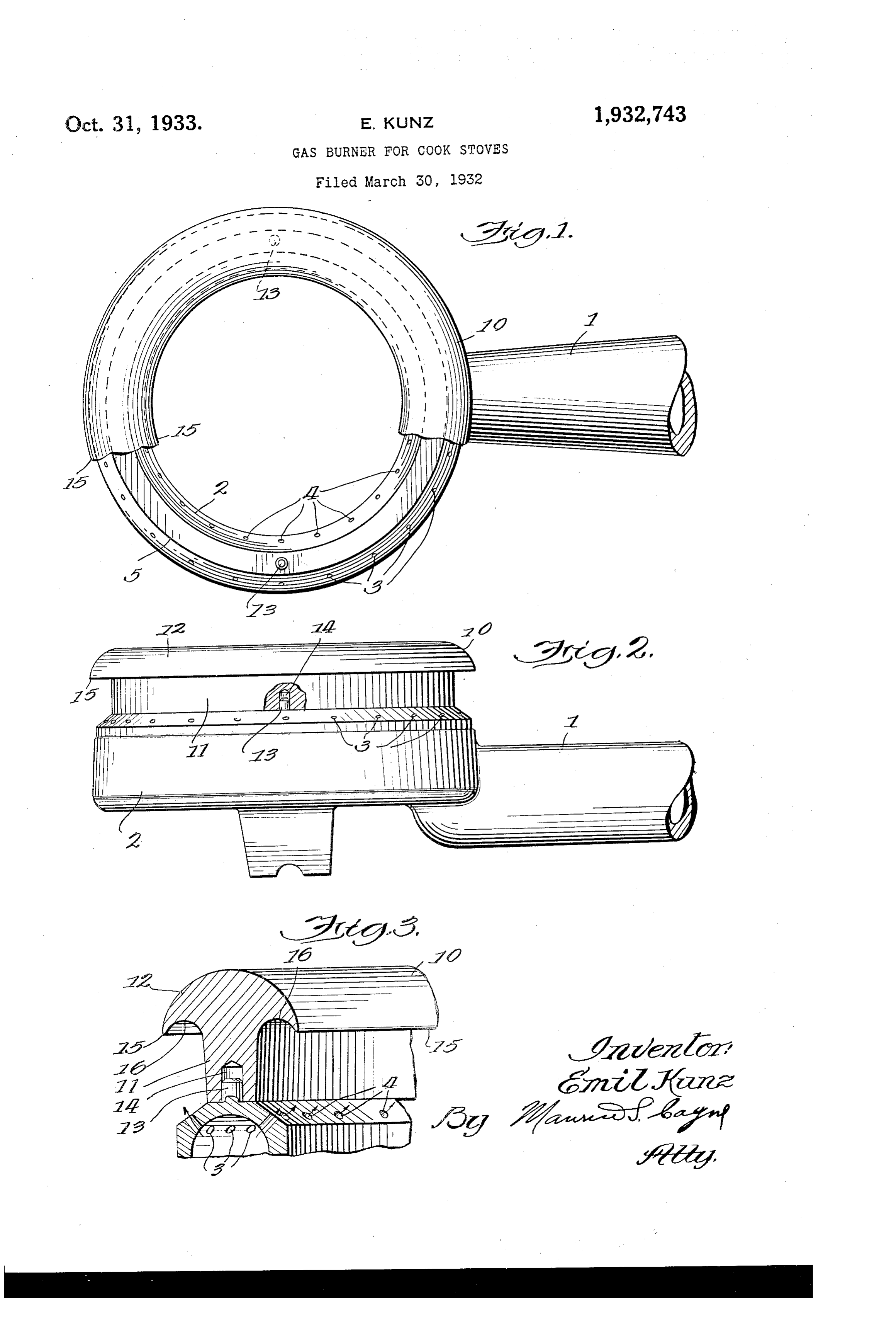
should be readily understood and ap- C3 a novel and improved attachment for the gas Referring to the drawing, in which similar burner of a cook stove, or the like, which attach characters of reference are employed to indi ment is adapted to be disposed on Said burner cate corresponding or similar parts through the in position to protect the flames issuing from the 10 escape-orifices from becoming extinguished either several figures of the drawing: Figure 1 is a top plan view of a burner illus from a gust of wind, or from the spilling of liq trating my improved attachment disposed there uid that may drop down onto the burner.
Another object of this invention is to provide on, part of the latter being broken away for the for a gas burner of a cook stove or the like a plurpose of clearneSS;
Figure 2 is a side elevational view of a burn- 40 15 novel and improved attachment adapted for de er provided with my improved attachment; and tachable engagement onto the burner, to be dis posed thereon in position to protect the flame in Figure 3 is a view partly in section and partly issuing from the escape-orifices from becoming provided withof my elevation a fragmentary portion of a burner extinguished, said attachment being also adapted Referring to theimproved attachment thereon. drawing more specifically by 5 20 for becoming heated by the gas flame and to re characters of reference, the numeral 1 desig tain the heat for some period of time after the nates the gas inlet through which a supply of Supply of gas has been shut off. gas and air is furnished to the burner 2, the A further object of this invention is to provide latter being of annular formation and is pro a novel and improved attachment for a gas burn vided adjacent the upper end thereof with an 30 er, comprising a ring adapted for disposition. On annular row of the burner in such a manner as to protect the thereof and an annular escape-orifices 3 on the outside flame issuing from the escape-orifices of the on the inside thereof. The row of escape-orifices 4 burner from becoming extinguished either from orifices are Spaced from each said rows of escape a gust of wind, or by reason of liquid Spilling tively flat portion 5. The structure other by a rela 30 thereon, said ring being detachably secured in so far de- 35 place on the burner. scribed may be of standard and well known con A still further object of this invention is to struction,invention and as the same forms no part of the provide a novel and improved attachment present it is not thought necessary to adapted for use with gas burners for preventing describe it in more detail. My improved attachment, which is designated 90 35 the extinguishing of the fame issuing from the generally by the reference character 10, com escape-Orifices, said attachment being adapted prises a stem portion 11 and a hood portion 12, for easy connection with said burner, may be said stem portion being adapted for resting on manufactured at a low cost, and is highly effi cient for carrying out the purposes for which it the portion 5 of the burner. There are provided at diametrically opposite points on said burner 95 40 is designed.
With the foregoing and other objects in view a pair of upstanding pins or lugs 13, which are which will appear as the description proceeds, the adapted to cooperate with a pair of recesses 14 invention consists in certain novel and improved provided holding in the under side of the stem 11 for features of construction, arrangement and com Securely burner. The the attachment in place on the attachment may be made of any 100 45 bination of parts hereinafter more fully de suitable material, such as scribed, illustrated in the accompanying draw material is adapted to retain the iron or the like, which heat for a con ing and particularly pointed out in the appended siderable period of time after the supply of gas claims, it being understood that various changes in the form, size, shape and minor details of the has been shut off.
The hood portion 12 is curved on its upper sur- 105 50 construction may be made without departing face, as shown in the drawing and as the side from the Spirit or Sacrificing any of the advan portions 15 thereof project beyond the escape tages of the invention.
For the purpose of facilitating an understand orifices 3 and 4, it will prevent the spilling of . ing of my invention, I have illustrated in the liquid onto Said escape-orifices. As shown more clearly in Figure 3 of the drawing, the project- ll.0 accompanying drawing a preferred embodiment
Page 3
ing portions i5 of the hood are also curved as It is believed that my invention, its mode of shown at 16, So that the meeting edges of the construction and assembly, and many of its ad outer and inner curved surfaces of the hood por vantages should be readily understood from the tion 12 will come to a distinct point to form a foregoing without further description, and it will sharp edge as shown at 15 in Figure 3, whereby be manifest that while a preferred embodiment 80 the dropping of liquid onto Said outer curved of the invention has been shown and described, Surface of the hood 12 will result in said liquid for illustrative purposes, the structural details dropping off Said hood at the edges 15, which are, nevertheless, capable of Wide variation with will be beyond the escape-orifices. in the purview of my invention as defined in 0. By reason of the curved inner surface 16 of the appended claims.
the hood, the possibility of liquid traveling along What I claim and desire to secure by Letters said surface and down the stem 11 will be prac Patent of the United States is:- tically avoided. By reason of the above con 1. A gas burner having in combination a Sup Struction it will be apparent that should any ply tube, and an annular gas receiving chamber, liquid be Spilled onto the hood 12, the same Will said chamber being formed Within a ring, the 90 roll off the Side portions thereof without coming upper portion of which is contracted and is pro into contact with the escape-orifices to cause the vided with inner and outer concentric lines of extinguishing of the flame issuing therefron. orifices arranged just below the uppermost edge A further feature of this construction is that of said ring, and an attachment disposed on the 20 it will not be possible for a gust of wind or the upper edge of said ring being of Substantially 95 like to cause the extinguishing of the flame. T-shaped cross section, the stem portion of Said The reason for this is if this gust of wind should attachment resting on the upper edge of Said strike the burner on one side thereof, it will be ring and the hood portion of Said attachment noted that it will only be possible to extinguish projecting over both of said inner and outer the flame issuing from the orifices disposed on lines of orifices, the projecting sides of Said hood 00 the side from which the wind is coming, and it portion terminating in sharp edges. will not reach those orifices disposed on the in 2. A gas burner having in combination a Sup side of the burner, or on the outside of the re ply tube and an annular gas receiving chamber, note side of the burner. For that reason there said chamber being formed within a ring, which 30 will always be a Sufficient number of orifices still ring is provided at its upper portion with inner 105 left burning so as to prevent the extinguishing of and Outer lines of escape orifices arranged just the entire flame issuing from the burner. below the uppermost edge of Said ring, and a It will thus be noted that I have provided a member of substantially T-shaped CrOSS Section simple and inexpensive device, which may be disposed on Said upper edge of Said ring, means readily disposed in place on a gas burner, and for detachably securing said member in place on O when so disposed it will not only prevent the said ring, the upper portion of Said member extinguishing of the fame by reason of any having side edges thereof projecting over the Said spilled liquid onto the burner, or by any gusts of lines of orifices, the underside of Said projecting wind directed against the burner, but will also portions being curved. EM, KUNZ. 15 40 act as a heat retainer for a considerable period of time after the shutting off of the gas supply.
Provenance
- Collection
- Cited prior art
- Original PDF
- patentimages.storage.googleapis.com →
- Filed
- 1932-03-30
- Pages
- 3
- Method
- pdftotext (the PDF's own text layer) + pdftoppm 300dpi page scans
- Source
- Google Patents bibliographic record
- Granted
- 1933-10-31
- Inventors
- Kunz Emil
- Transcribed from
- patentimages.storage.googleapis.com →