patent · US4023939
Method and arrangement for purifying gases
17 May 1977
Page 1 — bibliographic record
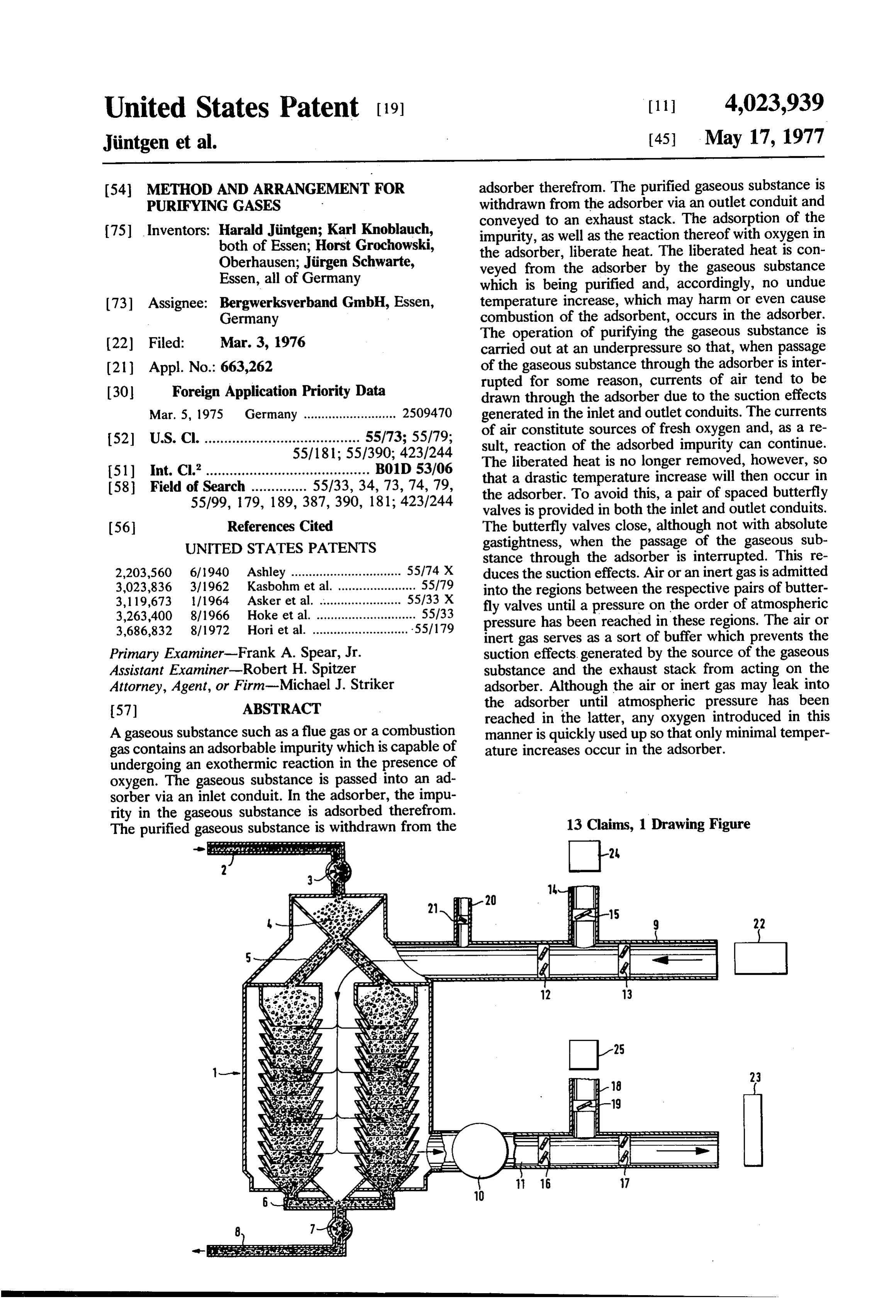
United States Patent (19) 11 4,023,939 Jintgen et al. (45) May 17, 1977 54 METHOD AND ARRANGEMENT FOR adsorber therefrom. The purified gaseous substance is PURIFYING GASES withdrawn from the adsorber via an outlet conduit and (75) Inventors: Harald Jintgen; Karl Knoblauch, conveyed to an exhaust stack. The adsorption of the both of Essen; Horst Grochowski, impurity, as well as the reaction thereof with oxygen in the adsorber, liberate heat. The liberated heat is con
Oberhausen; Jirgen Schwarte, veyed from the adsorber by the gaseous substance Essen, all of Germany which is being purified and, accordingly, no undue (73) Assignee: Bergwerksverband GmbH, Essen, temperature increase, which may harm or even cause Germany combustion of the adsorbent, occurs in the adsorber. The operation of purifying the gaseous substance is (22) Filed: Mar. 3, 1976 carried out at an underpressure so that, when passage (21) Appl. No.: 663,262 of the gaseous substance through the adsorber is inter 30 Foreign Application Priority Data rupted for some reason, currents of air tend to be drawn through the adsorber due to the suction effects
Mar. 5, 1975 Germany .......................... 2509470 generated in the inlet and outlet conduits. The currents 52 U.S. Cl. ....................................... 55/73; 55/79; of air constitute sources of fresh oxygen and, as a re 55/181; 55/390; 423/244 sult, reaction of the adsorbed impurity can continue.
(51) int. Cl”......................................... B01D 53/06 The liberated heat is no longer removed, however, so (58) Field of Search .............. 55/33, 34, 73,74, 79, that a drastic temperature increase will then occur in 55/99, 179, 189, 387, 390, 181; 423/244 the adsorber. To avoid this, a pair of spaced butterfly valves is provided in both the inlet and outlet conduits.
56 References Cited The butterfly valves close, although not with absolute UNITED STATES PATENTS gastightness, when the passage of the gaseous sub stance through the adsorber is interrupted. This re 2,203,560 6/1940 Ashley ............................... 55774 X duces the suction effects. Air or an inert gas is admitted 3,023,836 3/1962 Kasbohm et al. ...................... 55179 into the regions between the respective pairs of butter 3,119,673 1/1964 Asker et al. ......... ... 55/33 X fly valves until a pressure on the order of atmospheric 3,263,400 8/1966 Hoke et al. ............................ 55/33 pressure has been reached in these regions. The air or 3,686,832 8/1972 Hori et al. ........................... .55/179 inert gas serves as a sort of buffer which prevents the Primary Examiner-Frank A. Spear, Jr. suction effects, generated by the source of the gaseous Assistant Examiner-Robert H. Spitzer substance and the exhaust stack from acting on the Attorney, Agent, or Firm-Michael J. Striker adsorber. Although the air or inert gas may leak into 57) ABSTRACT the adsorber until atmospheric pressure has been reached in the latter, any oxygen introduced in this
A gaseous substance such as a flue gas or a combustion manner is quickly used up so that only minimal temper gas contains an adsorbable impurity which is capable of ature increases occur in the adsorber. undergoing an exothermic reaction in the presence of oxygen. The gaseous substance is passed into an ad sorber via an inlet conduit. In the adsorber, the impu rity in the gaseous substance is adsorbed therefrom. 13 Claims, 1 Drawing Figure The purified gaseous substance is withdrawn from the
Page 2
Drawing sheet — no readable text.
Page 3
adsorption zone. The stream of the gaseous substance
METHOD AND ARRANGEMENT FOR PURFYING is interrupted and thereafter a quantity of gas selected GASES from the group consisting of air and inert gases (waste BACKGROUND OF THE INVENTION gases such as flue gases or power plant combustion 5 gases, as well as other inert gases, may be used) is
The invention relates generally to the purification of forcibly admitted into both the upstream and down gaseous substances. Of particular interest to the inven stream sections of the path so as to raise the pressure in tion are a method and arrangement for the purification these sections of the path at least to the order of atmo of gaseous substances using adsorption, and especially spheric pressure.
a method and arrangement for removing oxides of 10 The raising of the pressures in the upstream and sulfur from waste gases at temperatures between about downstream sections of the pathis effective for restrict 80' and 160° C using carbonaceous adsorbents. ing the entry into the adsorption zone or adsorber of air It is known that waste gases such as, for example, the currents due to leakage and suction effects so that the combustion gases of power plants, may be desulfurized oxygen available in the adsorber and, resultantly, the at temperatures between about 80° and 160° C by the 15 extent of the exothermic reaction of the adsorbable adsorption of sulfur dioxide on carbonaceous adsor component, are restricted and an undue temperature bents. In the adsorber, the adsorbed sulfur dioxide increase in the adsorber due to the exothermic reaction (SO) oxidizes to SO which, in turn, leads to the for may be prevented.
mation of sulfuric acid. These reactions, as well as the The upstream section of the path along which the adsorption process, liberate heat so that a temperature 20 gaseous substance or waste gas flows may be located in increase occurs in the adsorbent. During the operation an inlet conduit which communicates with the adsorber of the apparatus in which the adsorption takes place, and with a source of the waste gas, e.g., a power plant. the liberated heat is removed from the adsorber by the The downstream section of the path along which the flowing waste gases so that no substantial temperature waste gas flows may be located in an outlet conduit increase occurs in the adsorbent. 25 which communicates with the adsorber and with an When the adsorber is put out of operation, uncon exhaust stack, for instance.
trolled quantities of air are sucked into the adsorber. Although the air or inert gas introduced into the This is due to the fact that the adsorption process is upstream and downstream sections of the path, that is, carried out at subatmospheric pressures. Thus, since into the inlet and outlet conduits, may be able to flow unavoidable leaks are present in the apparatus, and 30 into the adsorber, since the power plant and the exhaust stack through pressure interiorlysuch of flow will continue only until the the adsorber reaches the pressure which the purified waste gases are exhausted generate existing in the inlet and outlet conduits. This pressure is a suction effect, currents of air will be drawn into the advantageously approximately equal to atmospheric adsorber. These currents of air constitute a fresh source of oxygen and, as a result, reaction of the ad 35 pressure. After the pressure in the adsorber reaches the sorbed sulfur dioxide continues. In turn, heat continues air or inertthe pressure in gas inlet and outlet conduits, practically all admitted into the conduits will flow to be liberated in the adsorber. However, since the flow towards the exhaust stack. Any oxygen introduced into of the waste gases has been discontinued, the liberated the adsorber during the period in which the pressure in heat is no longer being removed from the adsorber so the latter is being equalized with that in the inlet and that a temperature increase can occur in the adsorbent. 40 outlet conduits is combusted or used in oxidation of the The temperature increase may be so large as to cause adsorbed impurity thereby causing a temperature in combustion of the carbonaceous material used as an adsorbent. crease in the adsorber. However, since the introduction of oxygen into the adsorber will be completely or al
SUMMARY OF THE INVENTION 45 most completely terminated upon equalization of the The invention intends to create a remedy for this pressures interiorly of the adsorber and the conduits, problem and to provide a method and arrangement for the temperature increase will be slight. The air or inert the purification of gaseous substances using adsorption gas admitted into the inlet and outlet conduits serves as which enable harmful temperature increases in the a sort of buffer which prevents the suction effects gen adsorbent to be avoided when operation of the adsor 50 erated by the power plant and exhaust stack from hav bent is interrupted. ing any substantial effect on the adsorber and, in partic This object, as well as others which will become ap ular, from continuously drawing currents of air into the parent as the description proceeds, are achieved in adsorber through leaks or openings which exist in the accordance with the invention. According to one as adsorber. It is such continuous currents of air which, in pect of the invention, there is provided a method of 55 the prior art, are responsible for the continued and purifying a gaseous substance, e.g., a waste gas such as dangerous oxidation of the adsorbed impurity subse flue gas or power plant combustion gas, which contains quent to interruption of the flow of the waste gases an adsorbable component or impurity, e.g., sulfur diox through the adsorber. Thus, as mentioned earlier, since ide, capable of undergoing exothermic reaction in the the heat generated by the oxidation is not removed presence of oxygen when adsorbed upon an adsorbent. 60 from the adsorber when the flow of waste gases through The method comprises conveying a stream of the gase the latter is interrupted, sharp temperature increases, ous substance along a path which includes an upstream which might harm the adsorbent, can occur in the ad section, a downstream section and an adsorption Zone sorber.
or adsorber for the adsorption of the adsorbable com As indicated previously, of special interest to the ponent intermediate the upstream and downstream 65 invention is a method of removing oxides of sulfur from sections. The conveying operation is carried out while waste gases by means of carbonaceous adsorbents. The maintaining subatmospheric pressures in the upstream adsorption is favorably carried out at temperatures and downstream sections of the path as well as in the between about 80 and 160 C.
Page 4
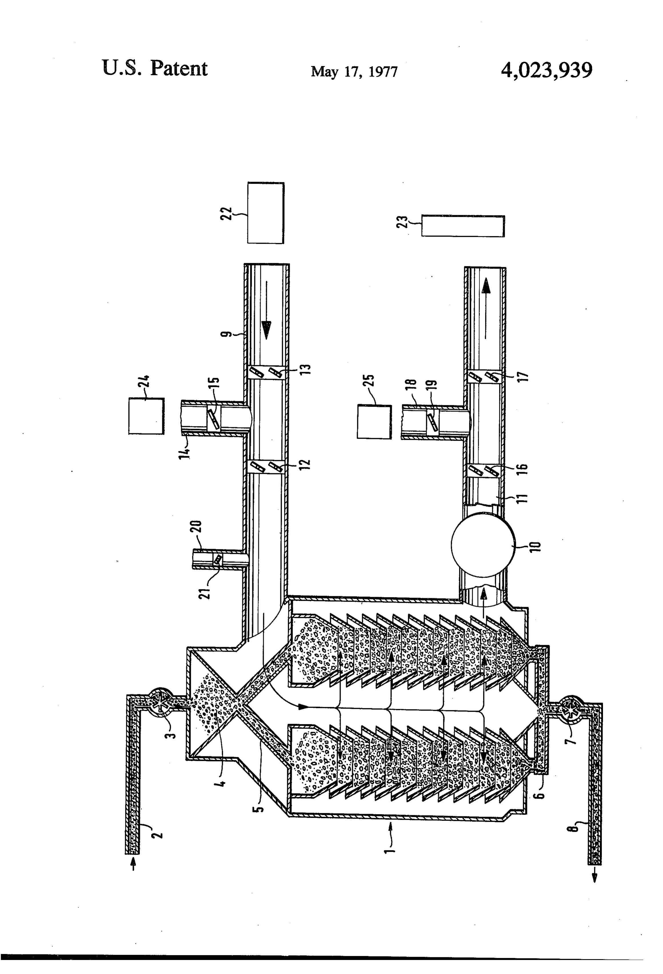
Thus, a preferred aspect of the invention relates to a The novel features which are considered as charac method of removing sulfur dioxide from waste gases teristic for the invention are set forth in particular in which are conveyed through an adsorber charged with the appended claims. The invention itself, however, a carbonaceous adsorbent. both as to its construction and its method of operation, According to a particularly advantageous embodi together with additional objects and advantages ment of the invention, the objects of the invention are thereof, will be best understood from the following achieved in that a pair of spaced valve members, e.g., description of specific embodiments when read in con butterfly valves, are provided in the conduit connecting nection with the accompanying drawing. the adsorber with the exhaust stack and in the conduit BRIEF DESCRIPTION OF THE DRAWING connecting the adsorber with the source of the waste 10 The single FIGURE is a schematic representation of gases, e.g., a power plant. The respective pairs of valve one embodiment of an arrangement in accordance with members are open during flow of the waste gases through the adsorber. Upon interruption of the stream the invention which may be used for carrying out a of waste gases, the respective pairs of valve members method according to the invention.
are closed. Subsequently, either air or inert gas, which 15 DESCRIPTION OF THE PREFERRED may be waste gas or some other inert gas, is admitted EMBODIMENTS into the spaces existing between the respective closed Referring to the single FIGURE, it is noted that the pairs of valve members in order to provide for a pres reference sure in these spaces which approximates atmospheric 20 tails of thenumeraladsorber 1 identifies an adsorber. Some de will be presented here not by way pressure. of limitation but, rather, in order to provide some per In order to achieve the desired pressure in the spaces spective.
between the respective pairs of valve members, it is The adsorber 1 is of annular configuration and has an possible to provide a regulating device which, upon overall diameter of 2.75 meters. The interior of the closing of the valve members, activates one or more 25 adsorber 1 also has the form of an annulus and the blowers which admit air or inert gas into the intermedi ate spaces between the respective pairs of valve mem diameter of the larger or outer ring of the internal annulus is 1.75 meters whereas the diameter of the bers until atmospheric pressure has been reached. smaller or inner ring of the internal annulus is 1 meter. It has been further found that a favorable safety mea The adsorber 1 has a height of 12 meters. sure resides in that the pressure in the inoperative ad 30 Three hundred cubic meters of a particulate carbo sorber is increased to above atmospheric pressure by naceous adsorbent are slowly moved through the ad the direct introduction of inert gas separately from the sorber 1 from the top to the bottom thereof. The dwell air or inert gas which is admitted into the spaces be time of the adsorbent in the adsorber 1 is 50 hours. tween the respective pairs of valve members. Depend The adsorbent is conveyed into the adsorber 1 via a ing upon the circumstances, the pressure in the ad 35 conduit 2. The adsorbent is passed into a charging sorber may be increased to a level which is only slightly device 3, which is here shown as being in the form of a above atmospheric pressure. The directly introduced bucket wheel, and is thereafter introduced into an ad inert gas makes it possible to avoid oxidation reactions mitting chamber 4. From the chamber 4, the adsorbent of the carbon in an adsorber containing a carbonaceous is fed into a conduit 5 of annular configuration which adsorbent with even greater certainty than would be 40 feeds the adsorbent into the annular interior of the possible otherwise. adsorber 1.
The invention also provides an arrangement for puri The adsorbent moves downwardly through the ad fying a gaseous substance, e.g., a waste gas such as flue sorber 1 and, upon reaching the bottom of the latter, gas or power plant combustion gas, which contains an enters a conduit 6. From the conduit 6, the adsorbent is adsorbable component or impurity capable of undergo 45 passed to a feeding member 7, which is here shown as ing exothermic reaction in the presence of oxygen being in the form of a bucket wheel. The feeding mem when adsorbed on an adsorbent. The arrangement ber 7 conveys the adsorbent into an outlet conduit 8 via comprises means defining a flow path for the waste gas which the adsorbent is discharged. and the flow path includes an upstream section, a The waste gas to be purified in the adsorber 1 is downstream section and an adsorption zone or ad 50 obtained from a source 22 of waste gas. Although the sorber intermediate these sections. Means is provided source 22 is here assumed to be a power plant so that for conveying the waste gas along the flow path under the waste gas is in the form of power plant combustion conditions such that subatmospheric pressures are gas, it will be understood that the source 22 could be maintained in the upstream and downstream sections any suitable source of gas to be purified and that the of the flow path as well as in the adsorber. The arrange 55 waste gas could, for example, be in the form offlue gas. ment further comprises means for forcibly admitting duitFrom 9 the source 22, the waste gas travels into a con which communicates with the interior of the gas into the upstream and downstream sections of the flow path so that, upon interruption of the flow of the adsorber 1. The conduit 9 is provided with a pair of waste gas along the flow path, the pressures in the valve members 12 and a pair of valve members 13 upstream and downstream sections of the flow path 60 which are in the form of butterfly valves in the illus may be raised to the order of atmospheric pressure. trated embodiment. The valve members 12 and the This enables the entry into the adsorber of air currents valve members 13 are spaced from one another in due to leakage and suction effects to be restricted longitudinal direction of the conduit 9. The valve mem whereby the oxygen available in the adsorber and, bers 12 and the valve members 13 are open when waste resultantly, the extent of the exothermic reaction of the 65 gasAfrom the source 22 flows through the conduit 9. conduit 14 communicates with the interior of the adsorbed component, may be restricted and an undue conduit 9 intermediate the valve members 12 and 13, temperature increase in the adsorber due to the exo that is, the conduit 14 opens into the space between the thermic reaction may be prevented.
Page 5
valve members 12 and the valve members 13. The and 13, as well as the valve members 16 and 17, are conduit 14 is provided with a valve member 15 which is closed.
here illustrated as being in the form of a butterfly valve. For a better understanding of the invention, it is The valve member 15 is closed when waste gas from mentioned here that valve members of the type illus the source 22 flows through the conduit 9. trated do not, as a rule, close so as to be gastight. This The conduit 14 is connected with a blower or com is of significance for an understanding of the method pressor 24. The blower 24, in turn, communicates with according to the invention. It is further pointed out that a source of air such as the atmosphere or with a source the adsorption arrangement is operated at a certain underpressure. Depending upon the power plant, the of inert gas.
In addition to the conduit 14, a conduit 20 communi adsorption 10 arrangement may, for instance, be operated cates with the interior of the conduit 9. The conduit 20 height of 350corresponding at a pressure millimeters.
to a water column having a is provided with a valve member 21 which is here also After the valve members 12 and 13, as well as the illustrated as being in the form of a butterfly valve. valve members 6 and 17, have been closed, the valve Similarly to the valve member 15, the valve member 21 15 members 15 and 19 are opened. Thereafter, air or inert is closed when waste gas from the source 22 flows gas is blown into the space between the closed valve through the conduit 9. The conduit 20 communicates members 12 and 13, as well as the space between the with a source of inert gas and a blower or compressor closed valve members 16 and 17, via the conduits 14 may be provided for admitting the inert gas from the and 18, respectively. In the illustrated embodiment, the conduit 20 into the conduit 9.
20 air or inert gas is blown into these intermediate spaces
After passing through the conduit 9, the waste gas enters the adsorber 1. The waste gas flows through the by the two blowers 24 and 25. However, it is to be understood that a single blower could be provided in adsorber 1 in a direction from top to bottom of the lieu of the two blowers 24 and 25 for blowing the air or adsorber 1 and the manner in which the waste gas flows inert gas into the through the adsorber 1 is indicated schematically by 25 The blowers 24 intermediate and 25 feed spaces.
air or inert gas into the the arrows in the adsorber 1. As the waste gas flows intermediate spaces until the pressure in the intermedi through the adsorber 1, the impurity or impurities ate spaces is on the order of atmospheric which it is desired to remove from the waste gas are is, the blowers 24 and 25 feed air or inertpressure, gas into that the adsorbed by the particulate carbonaceous adsorbent intermediate spaces in order to achieve atmospheric moving downwardly through the adsorber 1. It will be 30 pressure therein. Favorably, the blowers 24 and 25 are assumed here that the waste gas contains oxides of regulated in dependence upon the internal pressure of sulfur and, in particular, sulfur dioxide, and that it is the adsorber 1 in such a manner that they feed air or desired to remove the sulfur dioxide from the waste inert gas into the intermediate spaces for a period suffi gas, that is, that it is desired to desulfurize the waste cient for the pressure in the intermediate spaces to gas. 35 reach the vicinity of atmospheric pressure. In this man After having passed through the adsorber 1, the now ner, it becomes possible to avoid the uncontrolled entry purified waste gas leaves the latter via a blower or of air, which may cause dangerous temperature in compressor 10 which is installed in an outlet conduit creases due to oxidation reactions, into the adsorber 1. 11. The conduit 11 leads to an exhaust stack 23 The air or inert gas in the intermediate spaces serves as through which the purified waste gas may be exhausted 40 a sort of buffer between the adsorber 1 on the one hand into the atmosphere. and the power plant 22 and exhaust stack 23 on the The conduit 11 is provided with a pair of valve mem other hand. In this connection, it may be pointed out bers 16 and a pair of valve members 17 which are here that, if no means were provided for forcing air or inert illustrated as being in the form of butterfly valves. The gas into the conduits 9 and 11 and only the valve mem valve members 16 and the valve members 17 are 45 bers 12 and 16 were present in these conduits, air spaced from one another in longitudinal direction of would be sucked into the absorber 1 via the conduits 2 the conduit 11. The valve members 16 and the valve and 8 and sucked out of the adsorber 1 via the valve members 17 are open when purified waste gas from the members 12 and 16. The continuous air currents which adsorber 1 flows through the conduit 11. would be generated in the adsorber 1 in this manner are A conduit 18 communicates with the interior of the 50 responsible for the dangerous oxidation leading to conduit 11 intermediate the valve members 16 and 17, sharp temperature increases which may occur in the that is, the conduit 18 opens into the space between the inoperative adsorbers of the prior art. valve members 16 and the valve members 17. The As mentioned earlier, the valve members 12 and 13, conduit 18 is provided with a valve member 19 which is as well as the valve members 16 and 17, do not close here shown as being in the form of a butterfly valve. 55 with absolute gastightness. Therefore, the air or inert The valve member 19 is closed when purified waste gas gas blown into the intermediate spaces enters the ad from the adsorber 1 flows through the conduit 11. sorber 1 through the valve members 12 and 16 in rela The conduit 18 is connected with a blower or com tively significant amounts. Nevertheless, it is possible to pressor 25. The blower 25, in turn, communicates with blow air into the intermediate spaces instead of inert a source of air such as the atmosphere or with a source 60 gas. This is based on the fact that the gas introduced of inert gas. into the intermediate spaces flows into the adsorber 1 About 150,000 cubic meters of waste gas are con only until atmospheric pressure is reached in the ad veyed through the adsorber 1 per hour. The tempera sorber 1. As soon as atmospheric pressure is reached in ture in the adsorbent is between 130 and 140°C. It will the adsorber 1 or, more precisely, as soon as the pres be understood that the values provided here are only 65 sure in the adsorber 1 reaches the pressure in the inter exemplary. mediate spaces, practically all of the gas introduced In order to interrupt the desulfurization of the waste into the intermediate spaces will flow towards the gas, the blower 10 is shut off. The valve members 12 power plant 22 and the exhaust stack 23. Thus, the
Page 6
major part of the gas introduced into the intermediate tial characteristics of the generic or specific aspects of spaces will flow towards the power plant 22 and the this invention.
exhaust stack 23. The oxygen initially introduced into What is claimed as new and desired to be protected the adsorber 1 when air is blown into the intermediate by Letters Patent is set forth in the appended claims: spaces will combust so that a temperature increase contains 1. A method of purifying a gaseous substance which occurs in the adsorber 1. However, this temperature ing exothermic an adsorbable component capable of undergo increase is slight and insignificant and the oxygen is when adsorbed upon reaction in the presence of oxygen soon used up or else enters the adsorber 1 in such small ing a stream of said angaseousadsorbent, comprising convey amounts that any temperature increases remain slight. O which includes an upstream substance along a path section, a downstream
In the event that the nature of the adsorbent dictates section and an adsorption zone for the adsorption of that even a slight, transient increase in the temperature said of the adsorbent should be avoided, or in the event that veyingcomponent intermediate said sections, said con it is desirable to achieve a cooling or the adsorbent, spheric being carried out while maintaining subatmo inert gas such as, for example, nitrogen, may be intro 15 sections pressures in said upstream and downstream duced into the adsorber 1 via the conduit 20. In such a rupting said stream and of said path
in said adsorption zone; inter said gaseous substance; and case, the valve member 21, which is otherwise closed, thereafter forcibly admitting is shifted to its open position. The inert gas admitted via from the group consisting ofa air quantity of gas selected and inert gases into the conduit 20 is in addition to the gas which is intro each of said upstream and downstream duced into the intermediate spaces via conduits 14 and 20 path so as to raise the pressures in said sections sections of said of said 18. It is possible to increase the pressure in the ad path at least to the order of atmospheric pressure, said sorber 1 to above atmospheric pressure by the intro raising of the pressures being effective for restricting duction of inert gas through the conduit 20 and, de pending upon the circumstances, the pressure in the the entry into said adsorption zone of air currents due adsorber 1 may be increased to a value which is only 25 able in saidand to leakage suction effects so that the oxygen avail adsorption zone and, resultantly, the extent slightly above atmospheric pressure. of said exothermic reaction, are restricted and an Favorably, gas is admitted into the intermediate undue temperature increase in said adsorption zone spaces of the conduits 9 and 11 in such a manner, at due to said exothermic reaction may be prevented. least for the embodiment of the invention where no 2. A method as defined in claim 1, said upstream inert gas is introduced via the conduit 20, that the 30 section having an upstream end and said downstream pressures in the intermediate spaces are substantially section having a downstream end; and wherein said equal. This is especially advantageous when air is ad ends are partially blocked when said stream is inter mitted into the intermediate spaces. In the embodiment rupted so as to reduce suction effects in said adsorption of the invention where inert gas is introduced via the zone and said upstream and downstream sections of conduit 20, the pressure in the conduit 9 may exceed 35 said paths, at least part of said gas being admitted into that in the conduit 11. said upstream section downstream of said end thereof, Air should not be introduced through the conduit 20 and at least part of said gas being admitted into said since this may result in a significant temperature in downstream section upstream of said end thereof. crease in the adsorber 1. The conduit 20 is foreseen 3. A method as defined in claim 2, said upstream since inert gas such as nitrogen is expensive. Thus, if 40 section of said path having a downstream end, and said the inert gas which it is contemplated to introduce via downstream section of said path having an upstream the conduit 20 were to be introduced via the conduit 14 end; and wherein said downstream end of said up or the conduit 18, relatively substantial amounts of the stream section and said upstream end of said down inert gas would be lost through the valve member 13 or stream section are partially blocked when said stream is the valve member 17. By admitting the inert gas 45 interrupted so as to further restrict suction effects in through the conduit 20, these losses may be reduced. said adsorption zone, at least part of said gas being In order to renew operation of the arrangement, that admitted into said upstream section intermediate said is, in order to once again provide for desulfurization of ends thereof, and at least part of said gas being admit the waste gas, the valve members 15, 19 and 21 are ted into said downstream section intermediate said closed. The blower 10 is again activated and the valve 50 ends thereof.
members 12 and 13, as well as the valve members 16 4. A method as defined in claim 3, said upstream and 17, are opened. section of said path communicating with a combustion It will be understood that each of the elements de zone, and said downstream section of said path com scribed above, or two or more together, may also find municating with an exhaust stack; and wherein said a useful application in other types of methods and con 55 gaseous substance includes the combustion products structions differing from the types described above. from said combustion zone and said component is sul While the invention has been illustrated and de fur dioxide, said adsorption zone comprising a carbona scribed as embodied in a method and an arrangement ceous adsorbent, and said gas including a member of for desulfurizing combustion gases, it is not intended to the group consisting of air, flue gases and combustion be limited to the details shown, since various modifica 60 engine exhaust gases.
tions and structural changes may be made without 5. A method as defined in claim 1, wherein said gase departing in any way from the spirit of the present ous substance comprises a member of the group con invention. sisting of flue gases and power plant combustion gases. 6. A method as defined in claim 1, wherein said gas
Without further analysis, the foregoing will so fully 65 comprises reveal the gist of the present invention that others can, a member of the group consisting of air, flue by applying current knowledge, readily adapt it for gases and power plant combustion gases. various applications without omitting features that, 7. A method as defined in claim 1, said gas entering from the standpoint of prior art, fairly constitute essen said adsorption zone and raising the pressure therein to
Page 7
at most atmospheric pressure; and wherein an addi that, upon interruption of the flow of the gaseous sub tional quantity of gas in the form of inert gas is intro stance along said flow path, the pressures in said up duced into said adsorption zone so as to increase the stream and downstream sections may be raised to the pressure therein to above atmospheric pressure and order of atmospheric pressure so as to restrict the entry further restrict said exothermic reaction. into said adsorption zone of air currents due to leakage 8. A method as defined in claim 7, wherein said addi and suction effects, whereby the oxygen available in tional gas quantity increases the pressure in said ad said adsorption zone and, resultantly, the extent of sorption zone to a level which is only slightly above exothermic reaction of the adsorbed component, may atmospheric pressure. be restricted and an undue temperature increase in said 9. An arrangement for purifying a gaseous substance 10 adsorption zone due to the exothermic reaction may be which contains an adsorbable component capable of prevented, said admitting means including first admit undergoing exothermic reaction in the presence of ting means arranged to admit gas into said inlet conduit oxygen when adsorbed on an adsorbent, comprising intermediate said first and second valve members, and means defining a flow path for the gaseous substance, said admitting means including second admitting said flow path including an upstream section, a down 15 means arranged to admit gas into said outlet conduit stream section and an adsorption zone intermediate intermediate said other and additional valve members. said sections, and said means comprising an inlet con 10. An arrangement as defined in claim 9, wherein duit which includes said upstream section and an outlet said first and second admitting means each comprise an conduit which includes said downstream section, said admitting conduit opening into said inlet and outlet inlet conduit being provided with a first valve member 20 conduits, respectively; and valve members in said ad at an upstream end of said upstream section and with a mitting conduits.
second valve member at a downstream end of said 11. An arrangement as defined in claim 10, said ad upstream section, and said outlet conduit being pro sorption zone comprising a carbonaceous adsorbent; vided with another valve member at a downstream end and wherein said inlet conduit communicates with a of said downstream section and with an additional 25 combustion zone and said outlet conduit communi valve member at an upstream end of said downstream cates with an exhaust stack.
section, said valve members having open positions for 12. An arrangement as defined in claim 9, comprising permitting flow of the gaseous substance along said additional admitting means for admitting inert gas into flow path, and said valve members also having non-gas said adsorption zone so as to permit the exothermic tight closed positions to permit suction effects in said 30 reaction of the adsorbed component to be further re adsorption zone and said upstream and downstream stricted.
sections of said flow path to be reduced when flow of 13. An arrangement as defined in claim 9, said admit the gaseous substance along said flow path is inter ting means comprising at least one blower for blowing rupted; means for conveying the gaseous substance gas into said upstream and downstream sections of said along said flow path under conditions such that subat 35 flow path; and wherein said one blower is operative for mospheric pressures are maintained in said upstream admitting gas into said upstream and downstream sec and downstream sections thereof and in said adsorption tions of said flow path in dependence upon the pressure zone; and means for forcibly admitting gas into said existing interiorly ofck saidk adsorption
zone.
upstream and downstream sections of said flow path so

Provenance
- Collection
- Cited prior art
- Original PDF
- patentimages.storage.googleapis.com →
- Filed
- 1976-03-03
- Pages
- 7
- Method
- pdftotext (the PDF's own text layer) + pdftoppm 300dpi page scans
- Source
- Google Patents bibliographic record
- Granted
- 1977-05-17
- Inventors
- Harald Juntgen; Karl Knoblauch; Horst Grochowski; Jurgen Schwarte; Bergwerksverband GmbH
- Transcribed from
- patentimages.storage.googleapis.com →