patent · US2914688
Homopolar motor
24 November 1959
Page 1
Drawing sheet — no readable text.
Page 2
United States Patent Office 2,914,688 Patented Nov. 24, 1959
2,914,688 relatively large diameter connected thereto by a web
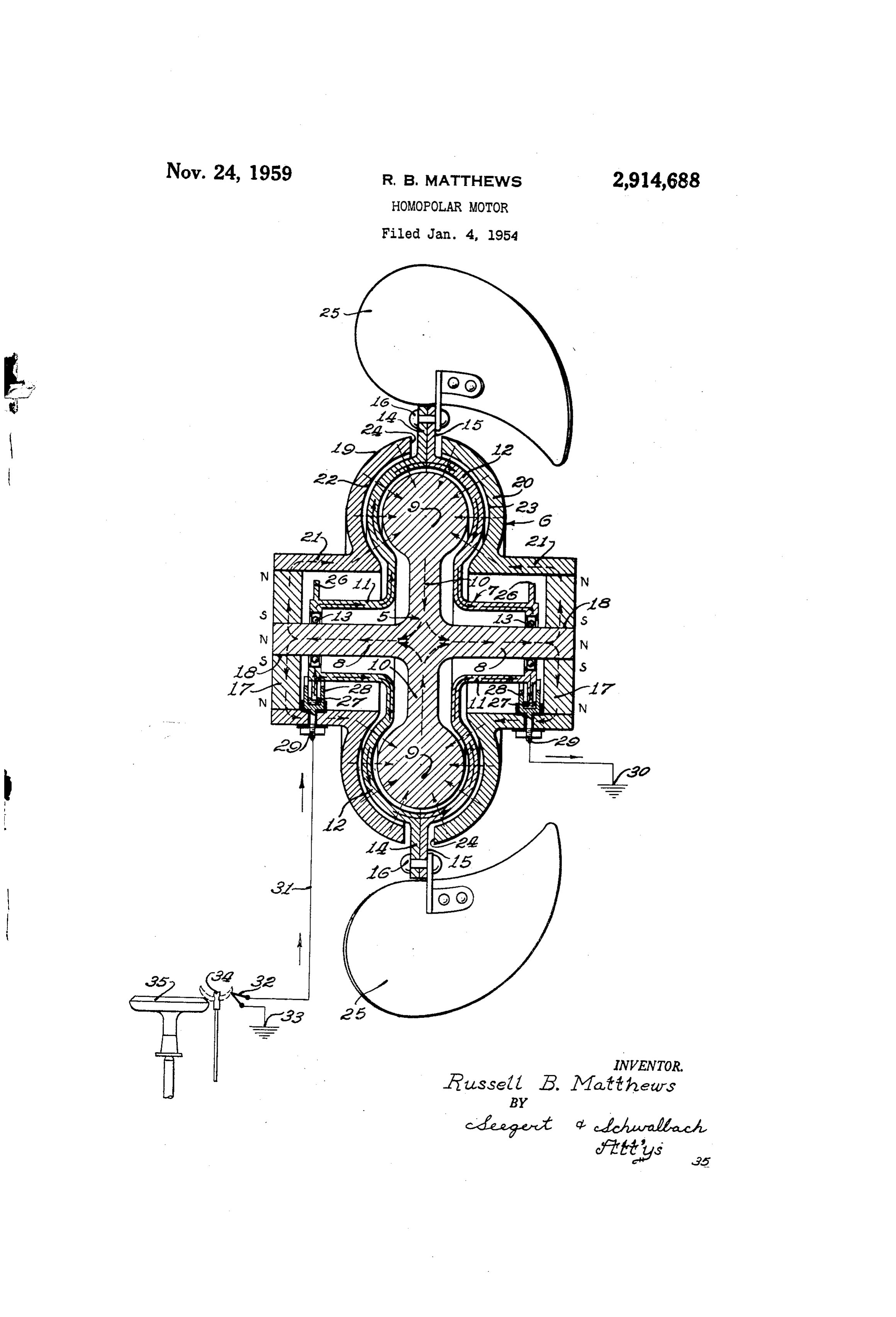
HOMOPOLAR MOTOR portion 10. The toroidal portion 9 may be generally circular in cross section, as shown.
Russell B. Matthews, Wauwatosa, Wis., assignor to Baso The rotor 7 is made of non-magnetic and electrically Inc., Milwaukee, Wis., a corporation of Wisconsin 5 conductive material, for example copper, and may com Application January 4, 1954, Serial No. 401,817 prise tubular cylindrical end portions 1 coaxially sur 10 Claims. (C. 310-178) rounding the core portion 8 in spaced relation, said rotor also being formed with an intermediate toroidal shell
This invention relates to improvements in electric like portion 12 which is spaced from and conforms to motors, and more particularly to motors which are oper 10 the contours of the portions 9 and 10 of the core 5. able on relatively small amounts of power, for example The outer ends of the rotor portions 11 are insulatably the power available from a thermoelectric generator. mounted on Suitable bearings 13, by which said rotor There are many installations in which it is desirable is journaled on the core portion 8. The rotor 7 may be formed in two sections as shown, said sections being to perform certain mechanical operations without utiliz 5 provided ing line power. Illustrative of such a case is the use with complementary peripheral flanges. 14 and of fresh air circulating means in a fluid fuel burning 15 suitably secured together as, by rivets 16. heater for increasing the heat transfer rate and thereby A pair of preferably identical circular permanent the efficiency of the apparatus in heating a given space. magnets 7 are centrally bored, as at 18, to receive the While thermoelectric power can be made readily avail 20 outer ends of the core portions 8 in flux conducting able in such apparatus, no satisfactory motor has been relation. The polarity of each of the magnets 17 is such developed which is operable on the limited power avail that one pole thereof is located at the margin of the aperture i8, and the other pole thereof is located at the able from a thermoelectric generator and which is capable periphery.
of performing a usable amount of work, for example powering air circulating means. The casing or frame 6 is formed of a pair of substan It is therefore a principal object of the present inven tially identical sections 19 and 20 which may take the tion to provide a motor of novel, and more particularly, form of metal stampings, each of said sections having a unipolar construction, said motor being operable on tubular cylindrical portion 21, the outer end of which thermoelectric power. has a coaxial Snug fit on the periphery of one of the Another object of the invention is to provide an im 30 permanent magnets 17 to provide a flux conducting proved electric motor characterized by high efficiency and connection. The casing sections 19 and 20 are also very low resistance. - provided with inner surface portions 22 and 23 which Another object of the invention is to provide an are spaced from and conform to the contours of the improved electric motor of the aforementioned character toroidal portion 12 of the rotor 7, as shown, to provide which lends itself to economical manufacture, said motor an effective air gap of generally toroidal shape between being fabricated largely from metal stampings and being 35 said Surface portions and said toroidal core portion. entirely devoid of windings. It is apparent that the Spacing between the casing sec A more specific object of the invention is to provide tions 19 and 20 provides a peripheral slot 24 in said an electric motor of the character described having a casing through which the rotor flanges i4 and 15 project magnetically permeable core and a magnetically per 40 for connection with one or more driven members, for meable casing having portions in flux conducting connec example impeller blades 25 fixed thereto by the rivets 16. tion and having other portions spaced to provide an Low-resistance and low-friction electrical connections annular air gap, there being permanent magnet means to the rotor 7 are afforded in the illustrated embodi for causing magnetic flux flow in said core, casing and said ment by radially outwardly directed ilanges 26 formed air gap, there also being a rotor of non-magnetic and 45 in the outer ends of the tubular rotor portions 11, said electrically conductive material having portions movable flanges extending into electrical contact with pools 27 in said air gap, and means including a source of thermo- . of an electrically conductive liquid, for example mercury, electric current for causing flow of said current through contained in metal receptacles 28. The receptacles 28 said rotor portions, to thereby cause turning movement are insulatably mounted within the casing 6 and have of the rotor. 50 terminal connectors 29 insulatably extending through Another object of the invention is to provide an said casing. One of the connectors 29 may be grounded, improved electric motor of novel toroidal construction as at 30, and a conductor 31 may connect the other which produces maximum rotor torque for a given flux connector 29 in circuit with one terminal of a source flow across the air gap and current flow through the rotor, of thermoelectric current, for example a thermocouple, said construction at the same time affording improved 55 said thermocouple having its other terminal grounded compactness. : as at 33. The thermocouple 32 may be suitably heated, Other objects and advantages of the invention will for example by subjecting it to the heat of the flame become apparent as the description proceeds, reference of a pilot burner 34, which burner may also coact with a main fuel burner 35.
being had to the accompanying drawing illustrating one form of the invention and wherein: - In the operation of the improved motor, magnetic ... The sole figure is a vertical sectional view of an 60 flux is generated by the permanent magnets 17 and flow electrical motor constructed in accordance with the therefrom, for example, as indicated by the broken arrows, invention and having electrical connections with a ther air i.e. through the casing sections 19 and 20, across the moelectric generator associated therewith and illustrated gap separating said sections from the portion 9 of 65 the core 5, and through said core back to the magnets 17.
Referring more particularly to the drawing, the im As indicated by the solid arrows, thermoelectric current proved electric motor is known generally as being of the from the thermocouple 32 enters one end of the rotor unipolar type and comprises, a core 5, a frame or casing 7 and flows through said rotor, including the portion 12 6 and a rotor 7. The core 5 is made of magnetically thereof located in the air gap, said current leaving the permeable material, and has a shaft-like portion 8. 70 rotor through the opposite end thereof and returning to Intermediate the ends of the shaft-like portion 8, the the thermocouple 32 through the ground circuit between core 5 is formed with a coaxial toroidal portion 9 of . grounds 30 and 33.
Page 3
The flow of thermoelectric current through the portion conforming to the shape of said air gap; permanent mag net means for causing magnetic flux flow in said casing, 12 of the rotor 7 establishes a field which reacts with the flux flowing across the air gap to provide a motor flow core and air gap; and a single thermocouple for causing action which urges the rotor 7 in a clockwise direction of low voltage current from one end of said rotor as viewed from the right in the drawing. Turning move 5 through the portion thereof within said air gap to the other end of said rotor to thereby effect turning move ment of the rotor 7, of course, causes actuation of the driven member or members, which in the illustrated en ment of said rotor, said rotor having a low resistance bodiment are the impeller blades 25, and which, when substantially equal to that of said thermocouple. actuated, provide gentle air circulation, for example in 2. An electric motor comprising: a magnetically the jacket of a space heater in which said motor may be O permeable core having intermediate and opposite end por mounted. tions; a magnetically permeable casing surrounding said The operation of the improved motor may be more core and comprising spaced sections non-rotatably fixed easily understood if it will be assumed that the rotor 7 thereto by flux-conducting connections with said opposite is comprised of an infinite number of conductors ex core end portions, portions of said casing sections being tending from one end of the rotor to the other. Thermo spaced from said intermediate core portions to provide electric current flow in each of the hypothetical conduc air gaps therewith; a low resistance rotor mounted for tors creates a circumferential field thereabout. The fiux rotation relative to said core and casing and having por flow in the air gap, being normal to said conductor, tions of non-magnetic and electrically conductive mate opposes and neutralizes the circumferential field on one 20 ed rial movable in said air gaps; a driven member connect side of the conductor and reinforces said field on the to said rotor in the space between said casing sections; opposite side of the conductor. The resulting unbal permanent magnet means for causing magnetic flux flow ance urges the conductor in a direction toward the side through said core, said casing sections and said air gaps; of the conductor at which the field thereof is neutralized. and a single thermocouple for causing flow of low volt By virtue of the fact that the toroidal air gap is spaced age electric current through the portions of said rotor a Substantial distance from the axis of the rotor, maxi within said air gaps to thereby effect turning movement of said rotor and actuation of the driven member, said mum torque is exerted on the rotor for a given amount of flux flow across the air gap and current flow through rotor portions having a low resistance substantially equal the rotor. This provides maximum efficiency, and the to 3.thatAnofelectric said thermocouple. motor comprising: a shaft-like core of novel toroidal conformation of the air gap and rotor affords relatively high power output for a given size 30 magnetically permeable material having an intermediate toroidal portion of enlarged diameter; a casing of mag notor.
netically permeable material having tubular end portions
The improved motor structure is characterized by very surrounding low resistance, being entirely devoid of energizing wind a toroidal inner the ends of said core, said casing also having ings and a commutator, and having a one piece rotor of the toroidal portion surface portion conforming to the shape of inherently low resistance. The low resistance of the to provide a toroidal airof gap, the core and spaced therefrom said casing being formed improved motor can be matched to the internal resist ance of the particular thermoelectric generator 32 utilized, with an annular peripheral slot at the toroidal surface portion thereof separating said casing into two spaced
So that maximum use is made of the power available Sections; an annular permanent magnet disposed with from said generator in operation of the motor.
It is within the concept of the invention to provide that 40 in the outer end of each casing section and surrounding the adjacent core end portion to afford a fixed flux-con the core 5 be a permanent magnet for producing the ducting connection with said core and casing end por flux flow indicated in the drawing. In such an event tions; a low resistance rotor of non-magnetic and elec the circular end members 17 need be only of magnetical ly permeable material rather than permanent magnet ma trically conductive material mounted for rotation relative to said core and casing and having a portion in the form terial. If desired, however, both the core 5 and the 45 of a toroidal shell disposed within and conforming to members 17 may form a single permanent magnet. the shape of said air gap; a driven member connected While the drawing illustrates the improved motor be ing used as part of an air circulating means, its use is tonentsaidmagnetsrotor through said annular casing slot; said perma causing magnetic flux flow in said core, cas by no means limited to the illustrated application, since ing sections and air gap; and a single thermocouple for it can be utilized equally well as a source of rotative 50 causing flow of low voltage electric current through the power in other applications.
The specific illustration and corresponding descrip portion of said rotor within said air gap to thereby effect tion are used for the purpose of disclosure only and are turning movement of said rotor and actuation of said driven member, said rotor having a low resistance sub not intended to impose unnecessary limitations on the 55 stantially equal to that of said thermocouple. claims, or to confine the patented invention to a particu 4. An electric motor comprising: a shaft-like core of lar use. Various changes and modifications may be made magnetically permeable material having an intermediate without departing from the spirit of the invention, and toroidal portion of enlarged diameter; a casing of mag all of such changes are contemplated as may come with netically permeable material having tubular end portions in the scope of the claims. 60 Surrounding the ends of said core, said casing also having What is claimed as the invention is:
1. An electric motor comprising: a shaft-like core of a toroidal inner surface portion conforming to the shape magnetically permeable material having an intermediate of the toroidal portion of the core and spaced therefrom toroidal portion of enlarged diameter; a casing of mag to provide a toroidal air gap; an annular permanent mag netically permeable material surrounding said core and 65 net disposed within each casing end portion and sur rounding the adjacent core end portion to afford a fixed non-rotatably fixed thereto by a flux-conducting connec flux-conducting connection with said core and casing end tion therewith, said casing also having a toroidal inner portions; a rotor of non-magnetic and electrically con surface portion conforming to the shape of the toroidal ductive material mounted for rotation relative to said portion of the core and spaced therefrom to provide a toroidal air gap; a tubular low resistance rotor of non 70 core and casing and having a portion in the form of a magnetic and electrically conductive material mounted toroidal shell disposed within and conforming to the shape of said air gap; said permanent magnets causing magnetic for rotation relative to said core and casing and coaxially surrounding said core within said casing, said rotor hav flux flow in said core, casing and air gap; and means for ing opposite ends and also having an intermediate por connecting said rotor to a source of direct current for tion in the form of a toroidal shell disposed within and s causing flow of direct current through the portion of
Page 4
said rotor within said air gap to thereby effect turning magnetic and electrically conductive material mounted movement of said rotor. for rotation relative to said core and casing and coaxial 5. An electric motor comprising: a shaft-like perma ly surrounding said core within said casing, said rotor nent magnet core having an intermediate toroidal por having opposite ends and also having an intermediate tion of enlarged diameter; a casing of magnetically perme portion in the form of a toroidal shell disposed within able material having tubular end portions surrounding the and conforming to the shape of said air gap; permanent ends of said, core, said casing also having a toroidal magnet means for causing magnetic flux flow in said cas inner surface portion conforming to the shape of the ing, core and air gap; and means for causing flow of toroidal portion fo the core and spaced therefrom to unidirectional current from one end of said rotor through provide a toroidal air gap; means affording a fixed flux the portion thereof within said air gap to the other end conducting connection between the adjacent core and of said rotor to thereby effect turning movement of said casing end portions; a rotor of non-magnetic and elec rotor.
trically conductive material mounted for rotation rela 9. An electric motor comprising: a magnetically perme tive to said core and casing and having a portion in the able core having intermediate and opposite end portions; form of a toroidal shell disposed within and conforming a magnetically permeable casing Surrounding said core to the shape of said air gap; the permanently magnetic and comprising spaced sections non-rotatably fixed there character of said core causing magnetic flux flow in said to by flux conducting connections with said opposite core casing and air gap; and means for connecting said rotor end portions, portions of said casing section being spaced to a source of direct current for causing flow of direct from said intermediate core portions to provide air gaps current through the portion of said rotor within said air 20 therewith; a low resistance rotor mounted for rotation gap to thereby effect turning movement of said rotor. relative to said core and casing and having portions of 6. An electric motor comprising: a shaft-like core of non-magnetic and electrically conductive material mov magnetically permeable material having an intermediate able in said air gaps; a driven member connected to said toroidal portion of enlarged diameter; a casing of mag rotor in the space between said casing sections; perma netically permeable material having tubular end portions 25 nent magnet means for causing magnetic flux flow through surrounding the ends of said core, said casing also having said core, said casing sections and said air gaps; and means a toroidal inner surface portion conforming to the shape for causing flow of unidirectional current through the of the toroidal portion of the core and spaced therefrom portions of said rotor within said air gaps to thereby to provide a toroidal air gap; an annular permanent mag effect turning movement of said rotor and actuation of the net disposed within each casing end portion and surround 30 driven member.
ing the adjacent core end portion to afford a fixed flux 10. An electric motor comprising: a shaft-like core of conducting connection with said core and casing end magnetically permeable material having an intermediate portions; a rotor of non-magnetic and electrically conduc toroidal portion of enlarged diameter; a casing of mag tive material mounted for rotation relative to said core netically permeable material having tubular end portions and casing and having a portion in the form of a toroidal 35 surrounding the ends of said core, said casing also having shell disposed within and conforming to the shape of said a toroidal inner surface portion conforming to the shape air gap; said permanent magnets causing magnetic flux of the toroidal portion of the core and spaced therefrom flow in said core, casing and air gap; means for connecting to provide a toroidal air gap, said casing being formed said rotor to a source of direct current for causing flow within an annular peripheral slot at the toroidal sur of direct current through the portion of said rotor with 40 face portion thereof separating said casing into two space in said air gap to thereby effect turning movement of sections; an annular permanent magnet disposed within said rotor; a member to be driven; and means affording the outer end of each casing section and surrounding the a driving connection between said rotor and said mem adjacent core end portion to afford a fixed flux-conducting ber to be driven. connection with said core and casing end portions; a low 7. An electric motor comprising: a shaft-like perma 45 resistance rotor of non-magnetic and electrically conduc nent magnet core having an intermediate toroidal por tive material mounted for rotation relative to said core tion of enlarged diameter; a casing of magnetically perme and casing and having a portion in the form of a toroidal able material having tubular end portions surrounding the shell disposed within and conforming to the shape of said ends of said core, said casing also having a toroidal inner air gap; a driven member connected to said rotor through surface portion conforming to the shape of the toroidal 50 said annular casing slot; Said permanent magnet causing portion of the core and spaced therefrom to provide a magnetic flux flow in said core, casing sections and air toroidal air gap; means affording a fixed flux conducting gap; and means for causing flow of unidirectional elec connection between the adjacent core and casing end por tric current through the portion of said rotor within said tions; a rotor of non-magnetic and electrically conductive air gap to thereby effect turning movement of said rotor material mounted for rotation relative to said core and 55 and actuation of said driven member. casing and having a portion in the form of a toroidal shell disposed within and conforming to the shape of References Cited in the file of this patent said air gap; the permanently magnetic character of said UNITED STATES PATENTS core causing magnetic flux flow in said casing and air 288,817 Kimball -------------- Nov. 20, 1883 gap; means for connecting said rotor to a source of di 60 293,758 Lubke ---------------- Feb. 19, 1884 rect current for causing flow of direct current through the 341,097 DeFerranti------------ May 4, 1886 portion of said rotor within said air gap to thereby effect 375,255 Blades ---------------- Dec. 20, 1887 turning movement of said rotor; a member to be driven; 1,199,444 Varley ---------------- Sept. 26, 1916 and means affording a driving connection between said 65 1,236,309 Johnson -------------- Aug. 7, 1917 rotor and said member to be driven. 1,262,585 Hollingshead ------------ Apr. 9, 1918 8. An electric motor comprising; a shaft-like core of 1,564,877 Marcellus -------------- Dec. 8, 1925 magnetically permeable material having an intermediate 1,838,146 Klopsteg -------------- Dec. 29, 1931 toroidal portion of enlarged diameter; a casing of mag 2,362,259 Findley ---------------- Nov. 7, 1944 netically permeable material surrounding said core and 70 2,482,847 Godman -------------- Sept. 27, 1949 non-rotatably fixed thereto by a flux conducting connec 2,539,569 Clark ----------------- Jan. 30, 1951 tion therewith, said casing also having a toroidal inner FOREIGN PATENTS surface portion conforming to the shape of toroidal 59,409 Germany -------------- Oct. 17, 1891 portion of the core and spaced therefrom to provide a 701,855 Germany -------------- Jan. 24, 1941 toroidal air gap; a tubular low resistance rotor of non 5 894,422 France --------------- Mar. 13, 1944
Provenance
- Collection
- Cited prior art
- Original PDF
- patentimages.storage.googleapis.com →
- Filed
- 1954-01-04
- Pages
- 4
- Method
- pdftotext (the PDF's own text layer) + pdftoppm 300dpi page scans
- Source
- Google Patents bibliographic record
- Granted
- 1959-11-24
- Inventors
- Russell B Matthews; Baso Inc
- Transcribed from
- patentimages.storage.googleapis.com →