patent · US4270282
Housed clothes dryer
2 June 1981
Page 1 — bibliographic record
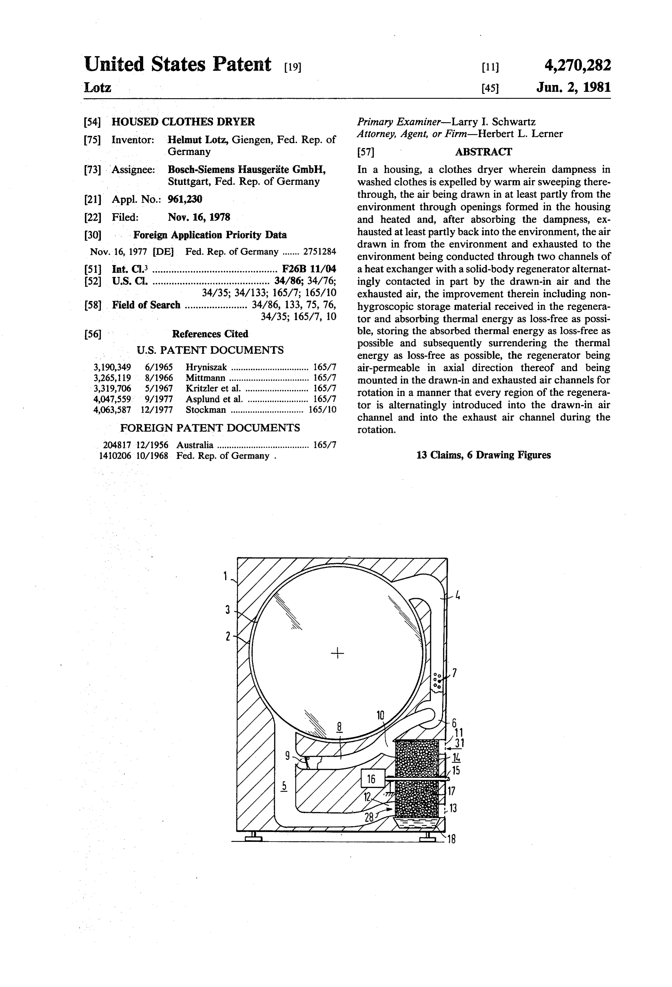
United States Patent (19) (11) 4,270,282 Lotz 45 Jun. 2, 1981 54 HOUSED CLOTHES DRYER Primary Examiner-Larry I. Schwartz (75) Inventor: Helmut Lotz, Giengen, Fed. Rep. of Attorney, Agent, or Firm-Herbert L. Lerner Germany 57 ABSTRACT 73 Assignee: Bosch-Siemens Hausgeräte GmbH, In a housing, a clothes dryer wherein dampness in Stuttgart, Fed. Rep. of Germany washed clothes is expelled by warm air sweeping there (21) Appl. No.: 961,230 through, the air being drawn in at least partly from the environment through openings formed in the housing 22 Filed: Nov. 16, 1978 and heated and, after absorbing the dampness, ex 30 . . . Foreign Application Priority Data hausted at least partly back into the environment, the air drawn in from the environment and exhausted to the
Nov. 16, 1977 DE Fed. Rep. of Germany ....... 2751284 environment being conducted through two channels of 51 int. C. .............................................. F26B 11/04 a heat exchanger with a solid-body regenerator alternat 52 U.S.C. ........................................... 34/86; 34/76; ingly contacted in part by the drawn-in air and the 34/35; 34/133; 165/7; 165/10 exhausted air, the improvement therein including non 58. Field of Search ....................... 34/86, 133, 75, 76, hygroscopic storage material received in the regenera 34/35; 165/7, 10 tor and absorbing thermal energy as loss-free as possi 56) References Cited ble, storing the absorbed thermal energy as loss-free as
possible and subsequently surrendering the thermal energy as loss-free as possible, the regenerator being 3,190,349 6/1965 Hryniszak ................................ 165/7 air-permeable in axial direction thereof and being 3,265, 19 8/1966 Mittmann ................................. 165/7 mounted in the drawn-in and exhausted air channels for 3,319,706 5/1967 Kritzler et al. .......................... 65/7 rotation in a manner that every region of the regenera 4,047,559 9/1977 Asplund et al. ......................... 165/7 tor is alternatingly introduced into the drawn-in air 4,063,587 - 12/1977 Stockman .............................. 65/10 channel and into the exhaust air channel during the
FOREIGN PATENT DOCUMENTS rotation.
20481712/1956 Australia ...................................... 165/7 1410206 10/1968. Fed. Rep. of Germany . 13 Claims, 6 Drawing Figures
XeX
Page 2
Drawing sheet — no readable text.
Page 3
Drawing sheet — no readable text.
Page 4
free as possible and subsequently surrendering the ther
HOUSED CLOTHES DRYER mal energy as loss-free as possible, the regenerator being air-permeable in axial direction thereof and being
The invention relates to a housed clothes dryer i.e. a mounted in the drawn-in and exhausted air channels for clothes dryer installed in a housing, wherein moisture or 5 rotation in a manner that every region of the regenera dampness in washed clothes is expelled by warm air tor is alternatingly introduced into the drawn-in air sweeping therethrough the air being drawn in at least channel and into the exhaust air channel during the partly from the environment and heated and, after ab rotation.
sorbing the dampness, exhausted at least partly back In the clothes dryer according to the invention, the into the environment, the air drawn in or supplied from 10 condensate cannot be transported in the regenerator to the environment and the air exhausted to the environ the supplied or drawn-in air because it drains off before ment being conducted through two channels of a heat hand due to the action of gravity. The supplied or exchanger with a solid-body regenerator alternatingly drawn-in air therefore remains dry. It merely absorbs, in contacted in part by the drawn-in or supplied air and the regenerator, only the thermal energy contained in the exhausted air. 15 the storage material whereby a great part of the injected Such a clothes dryer has become known heretofore thermal energy is continuously kept in circulation from German Published Non-Prosecuted Application within the dryer. Only a small part of the thermal en DE-OS No. 14 10 206 wherein two hollow members ergy escapes unavoidably with the draining condensate. formed of porous concrete are respectively provided The invention has the further advantage that, with con with two connecting channels, a respective one of 20 tinuous, slow rotation of the regenerator, a very exten which being connected to ambient air. Both of the other sive and uniform heat return by and dehumidification of connecting channels are alternately connectible by the exhaust gas can be attained.
means of a change-over valve to a supplied or drawn-in In accordance with another feature of the invention, air channel or to an exhaust air channel. Moisture or that is of relatively simple construction and especially dampness contained in the exhaust air condenses in the 25 economical, the regenerator comprises a basket filled initially cooler hollow member and must be removed with the storage material.
therefrom in a manner not disclosed in the German When, further in accordance with the invention, the published application. This hollow member gradually basket is filled with mineral granules, with ceramic absorbs so much thermal energy from the exhaust air filling bodies having a glazed surface or with metal as and the condensate, however, that heat transfer from 30 storage material or with an helical sheetmetal coil hav the exhaust air to the hollow members and condensation ing winding cross sections disposed at an angle to be can barely occur. At the latest, by that time, the valve axis or shaft of the regenerator, it may be of advantage, must change over, thereby connecting the other hollow in accordance with an added feature of the invention to member, which had been cooled by the drawn-in or provide, in the regenerator, the drawn-in or supplied supplied air in the interim, to the exhaust air channel 35 and the exhaust air channels with a spacing therebe and the heated-up hollow member to the drawn-in or tween which is greater than the lengths of drawn-in and supplied air channel. exhaust air travel paths within the regenerator. In the heretofore known embodiment of the afore On the other hand, in accordance with an alternate mentioned German published application, the exhaust feature of the invention, at least three partitions are air is cooled down and dehumidified only very nonuni disposed in the basket in a manner that, independently formly and incompletely. Due to the construction of the of the rotary position of the regenerator, no air flow hollow members and the material used therefor, the from the exhaust air channel to the drawn-in or supplied drawn-in or supplied air is, in fact, fed back again to the air channel within the regenerator is permitted to the part of the condensate which has been absorbed by the respective air flow in the drawn-in or supplied air chan material of the hollow body out of the exhaust air. The 45 nel and in the exhaust air channel. drying operation can thereby last considerably longer When, in accordance with the invention, the regener and can consume considerably more energy than with ator comprises an air-permeable array of metal sheets the conventional method of condensing the moisture or disposed in axial direction of the regenerator, there is dampness in a water-cooled condenser. provided, in accordance with yet another feature of the It is accordingly an object of the invention to provide 50 invention, that the metal sheets are radially directed. an improved clothes dryer which affords more effective Then, the condensate depositing on the metal sheets can utilization of the thermal energy that is employed and drain off downwardly and be collected. which avoids any use of cooling water for drying. In accordance with yet a further feature of the inven With the foregoing and other objects in view, there is tion, the drawn-in or supplied and the exhaust air chan provided, in accordance with the invention, in a hous 55 nels have a cross-sectional area corresponding substan ing, a clothes dryer wherein dampness in washed tially to a circular sector whereby the heat exchange clothes is expelled by warm air sweeping therethrough, occurs in the greatest possible areal or spatial sector of the air being drawn in at least partly from the environ the regenerator. All of the storage bodies of the regen ment through openings formed in the housing and erator can thereby be utilized uniformly for heat trans heated and, after absorbing the dampness, exhausted at 60 fer.
least partly back into the environment, the air drawn in tionIn the accordance with yet an added feature of the inven exhaust air channel is located in a lowermost from the environment and exhausted to the environ ment being conducted through two channels of a heat region of the regenerator, whereby the condensate exchanger with a solid-body regenerator alternatingly draining downwardly due to the action of gravity can contacted in part by the drawn-in air and the exhausted 65 be discharged without special expense. air, non-hygroscopic storage material received in the In order to afford unrestricted drainage of the con regenerator and absorbing thermal energy as loss-free as densate, in accordance with yet an additional feature of possible, storing the absorbed thermal energy as loss the invention, the solid bodies of which the storage
Page 5
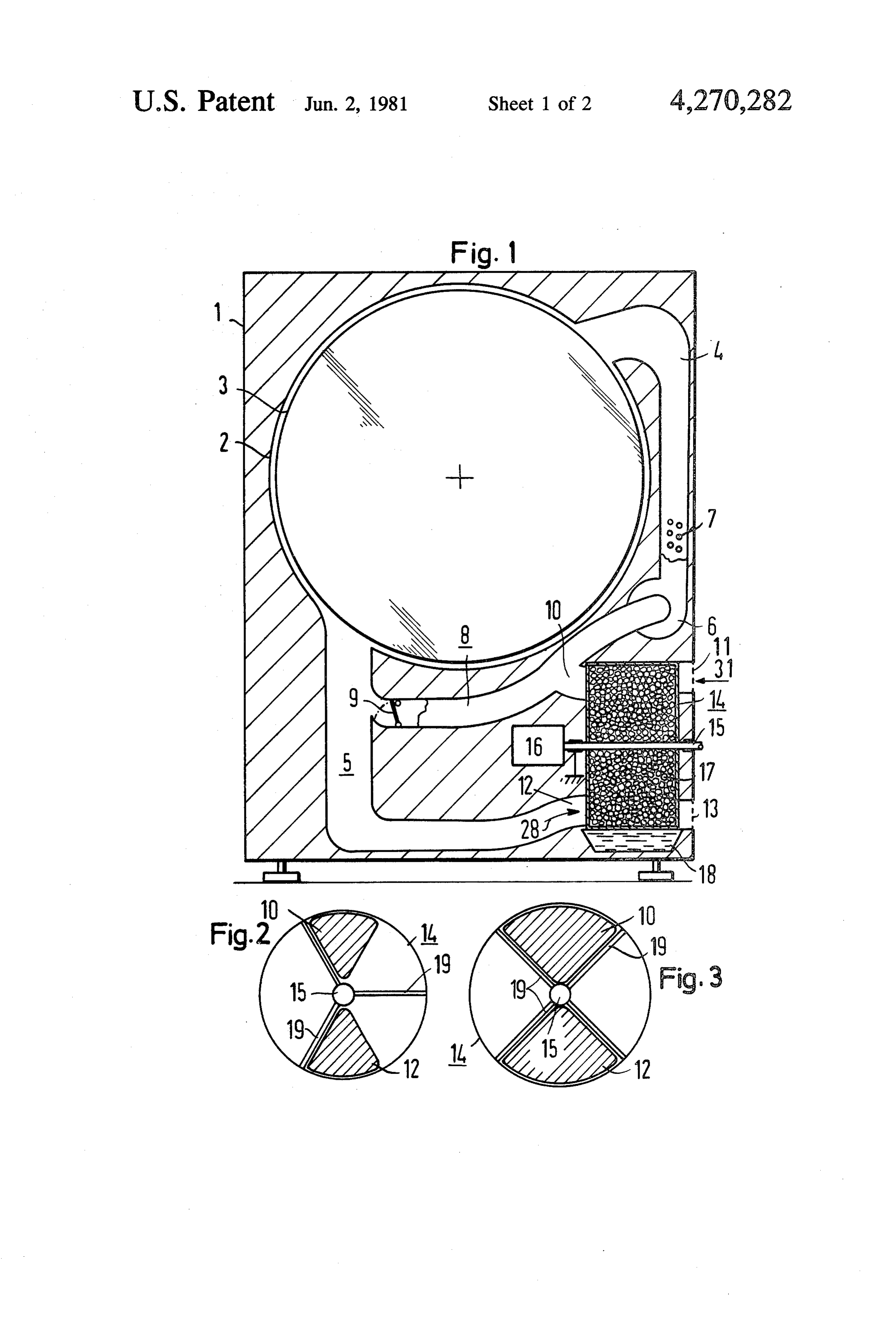
material is formed have a shape and location in the down transmission or reduction gearing. The regenera regenerator for facilitating flow-off or drainage of the tor 14 is formed primarily of a basket-like container water condensing from the exhaust air in a direction filled with a non-hygroscopic storage material 17. This transverse to the flow of exhaust air in the channel storage material 17 is supposed to absorb, free of any thereof. losses as possible, thermal energy tendered thereto, and In accordance with a concomitant feature of the in to surrender, free of any losses as possible, thermal vention, a condensate collecting vessel is disposed energy demanded therefrom. Thermal energy absorbed below the regenerator substantially in alignment with by the storage material should, however, remain stored the exhaust air channel. The condensate collecting ves as free of any losses as possible. Mineral granular mate sel can be connected, for example, to a discharge or 10 rial (stones or rocks), ceramic filling or packing material drain line. with glazed surfaces and metal, for example, are suitable Other features which are considered as characteristic materials for adequately satisfying the foregoing condi for the invention are set forth in the appended claims. tions.
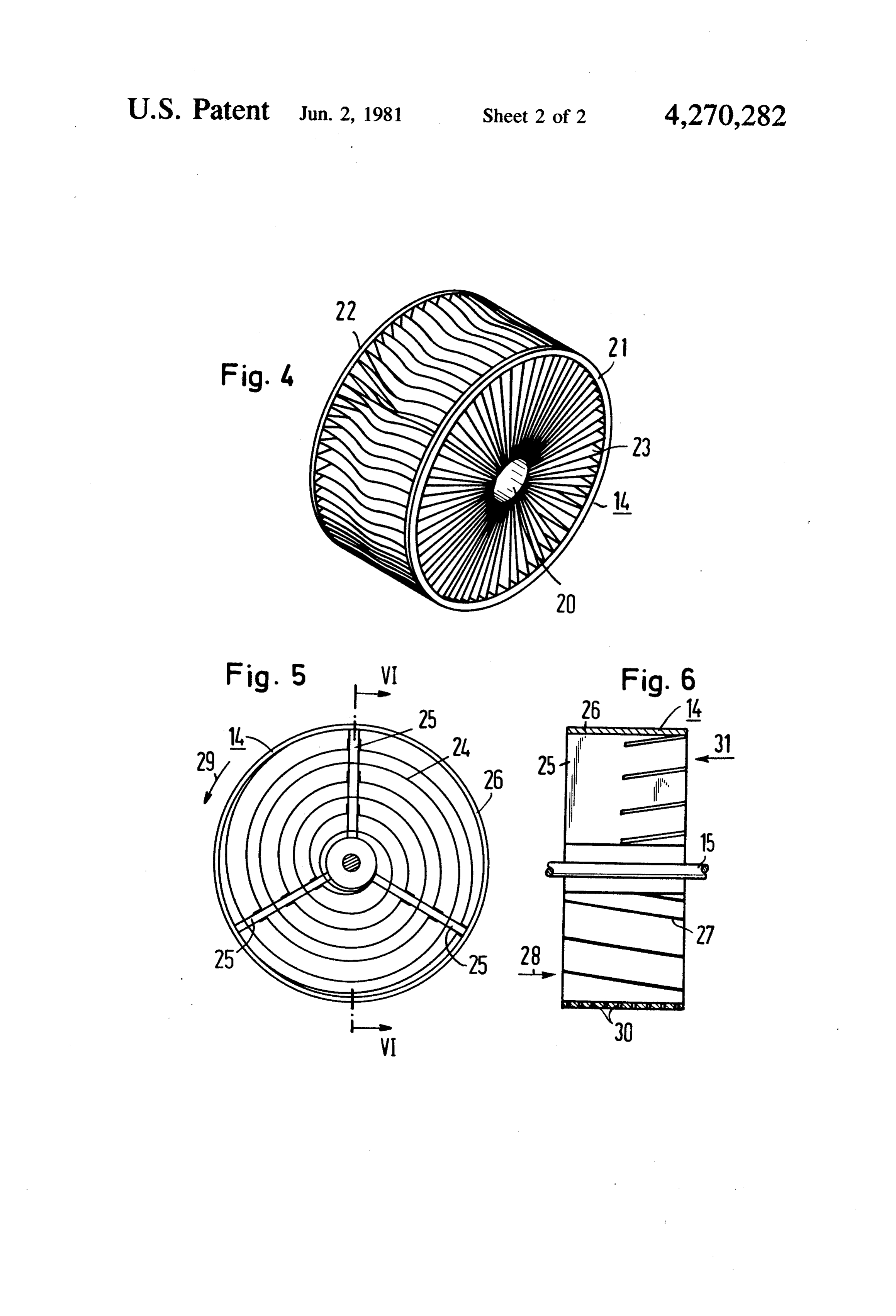
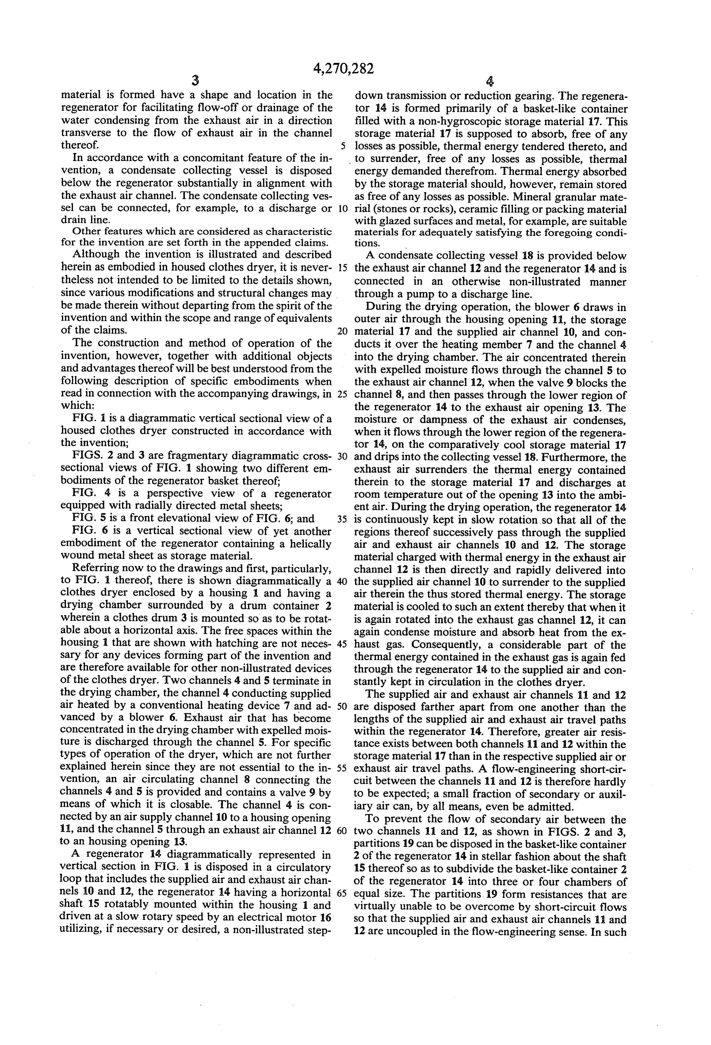
Although the invention is illustrated and described A condensate collecting vessel 18 is provided below herein as embodied in housed clothes dryer, it is never 15 the exhaust air channel 12 and the regenerator 14 and is theless not intended to be limited to the details shown, connected in an otherwise non-illustrated manner since various modifications and structural changes may through a pump to a discharge line. be made therein without departing from the spirit of the During the drying operation, the blower 6 draws in invention and within the scope and range of equivalents outer air through the housing opening 11, the storage of the claims. 20 material 17 and the supplied air channel 10, and con The construction and method of operation of the ducts it over the heating member 7 and the channel 4 invention, however, together with additional objects into the drying chamber. The air concentrated therein and advantages thereof will be best understood from the with expelled moisture flows through the channel 5 to following description of specific embodiments when the exhaust air channel 12, when the valve 9 blocks the read in connection with the accompanying drawings, in 25 channel 8, and then passes through the lower region of which: the regenerator 14 to the exhaust air opening 13. The FIG. 1 is a diagrammatic vertical sectional view of a moisture or dampness of the exhaust air condenses, housed clothes dryer constructed in accordance with when it flows through the lower region of the regenera the invention; tor 14, on the comparatively cool storage material 17 FIGS. 2 and 3 are fragmentary diagrammatic cross 30 and drips into the collecting vessel 18. Furthermore, the sectional views of FIG. 1 showing two different em exhaust air surrenders the thermal energy contained bodiments of the regenerator basket thereof; therein to the storage material 17 and discharges at FIG. 4 is a perspective view of a regenerator room temperature out of the opening 13 into the ambi equipped with radially directed metal sheets; ent air. During the drying operation, the regenerator 14 FIG. 5 is a front elevational view of FIG. 6; and 35 is continuously kept in slow rotation so that all of the FIG. 6 is a vertical sectional view of yet another regions thereof successively pass through the supplied embodiment of the regenerator containing a helically air and exhaust air channels 10 and 12. The storage wound metal sheet as storage material. material charged with thermal energy in the exhaust air Referring now to the drawings and first, particularly, channel 12 is then directly and rapidly delivered into to FIG. 1 thereof, there is shown diagrammatically a the supplied air channel 10 to surrender to the supplied clothes dryer enclosed by a housing 1 and having a air therein the thus stored thermal energy. The storage drying chamber surrounded by a drum container 2 material is cooled to such an extent thereby that when it wherein a clothes drum 3 is mounted so as to be rotat is again rotated into the exhaust gas channel 12, it can able about a horizontal axis. The free spaces within the again condense moisture and absorb heat from the ex housing 1 that are shown with hatching are not neces 45 haust gas. Consequently, a considerable part of the sary for any devices forming part of the invention and thermal energy contained in the exhaust gas is again fed are therefore available for other non-illustrated devices through the regenerator 4 to the supplied air and con of the clothes dryer. Two channels 4 and 5 terminate in stantly kept in circulation in the clothes dryer. the drying chamber, the channel 4 conducting supplied The supplied air and exhaust air channels 11 and 12 air heated by a conventional heating device 7 and ad 50 are disposed farther apart from one another than the vanced by a blower 6. Exhaust air that has become lengths of the supplied air and exhaust air travel paths concentrated in the drying chamber with expelled mois within the regenerator 14. Therefore, greater air resis ture is discharged through the channel 5. For specific tance exists between both channels 11 and 12 within the types of operation of the dryer, which are not further storage material 17 than in the respective supplied air or explained herein since they are not essential to the in 55 exhaust air travel paths. A flow-engineering short-cir vention, an air circulating channel 8 connecting the cuit between the channels 11 and 12 is therefore hardly channels 4 and 5 is provided and contains a valve 9 by to be expected; a small fraction of secondary or auxil means of which it is closable. The channel 4 is con iary air can, by all means, even be admitted. nected by an air supply channel 10 to a housing opening To prevent the flow of secondary air between the 11, and the channel 5 through an exhaust air channel 12 60 two channels 11 and 12, as shown in FIGS. 2 and 3, to an housing opening 13. partitions 19 can be disposed in the basket-like container A regenerator 14 diagrammatically represented in 2 of the regenerator 14 in stellar fashion about the shaft vertical section in FIG. 1 is disposed in a circulatory 15 thereof so as to subdivide the basket-like container 2 loop that includes the supplied air and exhaust air chan of the regenerator 14 into three or four chambers of nels 10 and 12, the regenerator 14 having a horizontal 65 equal size. The partitions. 19 form resistances that are shaft 15 rotatably mounted within the housing 1 and virtually unable to be overcome by short-circuit flows driven at a slow rotary speed by an electrical motor 16 so that the supplied air and exhaust air channels 11 and utilizing, if necessary or desired, a non-illustrated step 12 are uncoupled in the flow-engineering sense. In such
Page 6
a construction of the regenerator container 2, the effec regenerator and held substantially radially symmetri tive cross sections of the air channels 11 and 12 can be cally in a hollow cylinder, said metal sheets being increased to such an extent that at least one partition 19 formed of a helical sheetmetal coil having winding is always located between the inlets thereof into the cross sections disposed at an angle to the axis of the regenerator 14 independently of the rotary position of 5 regenerator.
the regenerator container 2. If the cross sections of the 2. Clothes dryer according to claim 1 wherein the inlets of the air channels 10 and 12 to the regenerator 14 regenerator further comprises a basket filled with said are circular sector-shaped, as in the embodiments of storage material.
FIGS. 2 and 3, the greatest possible cross-section sur 3. Clothes dryer according to claim 2 wherein said face can be attained, on the one hand, and the condensa 10 storage material is formed of mineral granules. tion and heat exchange in all parts of the storage mate 4. Clothes dryer according to claim 2 wherein said rial 17 can be uniformly effected, on the other hand. storage material is formed of ceramic filling bodies The embodiment of the regenerator 14 shown in having a glazed surface.
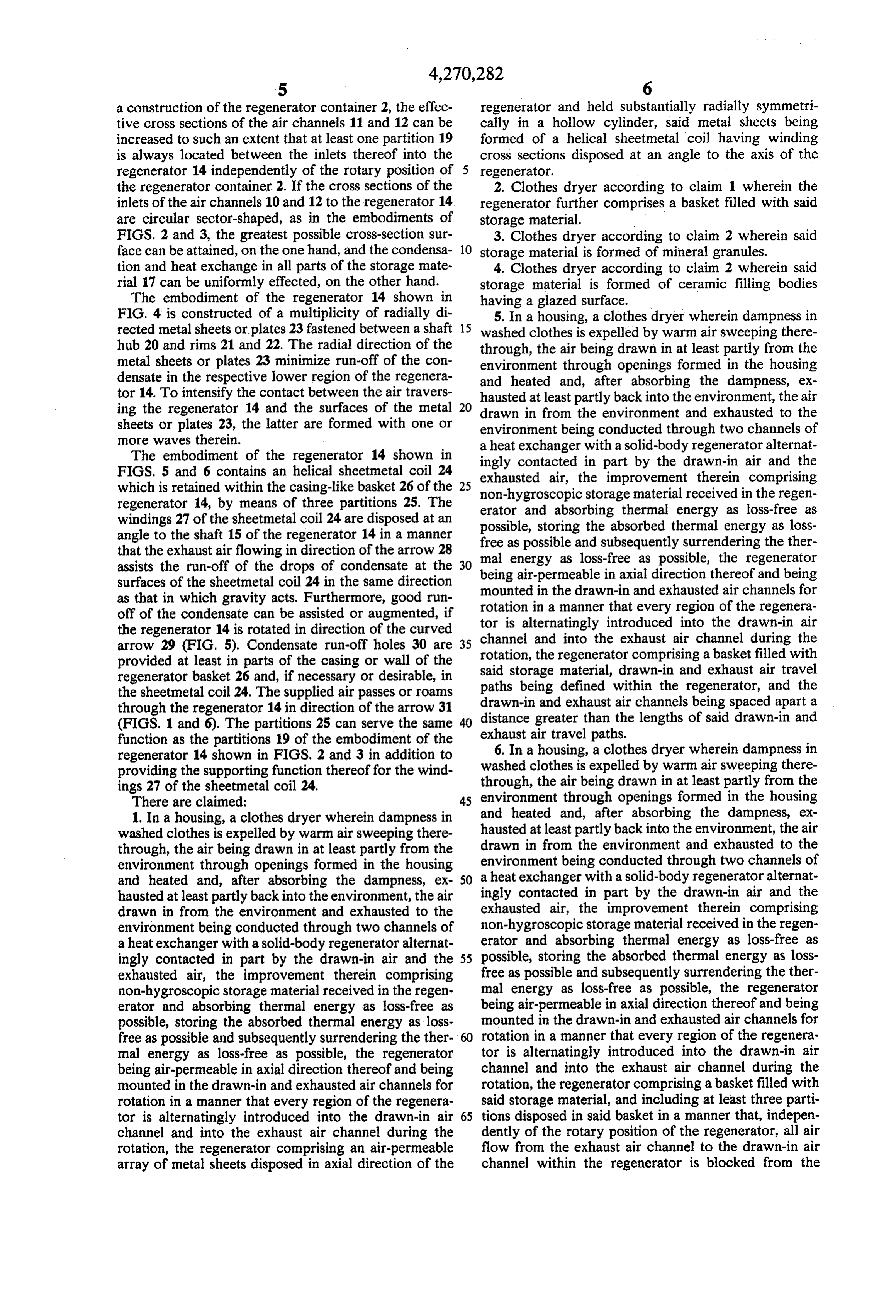
FIG. 4 is constructed of a multiplicity of radially di 5. In a housing, a clothes dryer wherein dampness in rected metal sheets or plates 23 fastened between a shaft 15 washed clothes is expelled by warm air sweeping there hub 20 and rims 21 and 22. The radial direction of the through, the air being drawn in at least partly from the metal sheets or plates 23 minimize run-off of the con environment through openings formed in the housing densate in the respective lower region of the regenera and heated and, after absorbing the dampness, ex tor 14. To intensify the contact between the air travers hausted at least partly back into the environment, the air ing the regenerator 14 and the surfaces of the metal 20 drawn in from the environment and exhausted to the sheets or plates 23, the latter are formed with one or environment being conducted through two channels of more waves therein. a heat exchanger with a solid-body regenerator alternat The embodiment of the regenerator 14 shown in ingly contacted in part by the drawn-in air and the FIGS. 5 and 6 contains an helical sheetmetal coil 24 which is retained within the casing-like basket 26 of the 25 exhausted air, the improvement therein comprising non-hygroscopic storage material received in the regen regenerator 14, by means of three partitions 25. The erator and absorbing thermal energy as loss-free as windings 27 of the sheetmetal coil 24 are disposed at an possible, storing the absorbed angle to the shaft 15 of the regenerator 14 in a manner free as possible and subsequentlythermal energy as loss surrendering the ther that the exhaust air flowing in direction of the arrow 28 mal energy as loss-free as possible, the regenerator assists the run-off of the drops of condensate at the being air-permeable in axial direction thereof and being
surfaces of the sheetmetal coil 24 in the same direction mounted in the drawn-in and exhausted air channels for as that in which gravity acts. Furthermore, good run rotation in a manner that every region of the regenera off of the condensate can be assisted or augmented, if tor is alternatingly the regenerator 14 is rotated in direction of the curved channel and into theintroduced into the drawn-in air arrow 29 (FIG. 5). Condensate run-off holes 30 are rotation, the regenerator comprisingchannel
provided at least in parts of the casing or wall of the said storage material, drawn-in and aexhaust basket filled with regenerator basket 26 and, if necessary or desirable, in paths being defined within the regenerator,airandtravel the sheetmetal coil 24. The supplied air passes or roams drawn-in and exhaust air channels being spaced apartthea through the regenerator 14 in direction of the arrow 31 distance greater than the lengths of said drawn-in and (FIGS. 1 and 6). The partitions 25 can serve the same function as the partitions 19 of the embodiment of the exhaust air travel paths.
6. In a housing, a clothes dryer wherein dampness in regenerator 14 shown in FIGS. 2 and 3 in addition to providing the supporting function thereof for the wind washedthrough, clothes is expelled by warm air sweeping there the air being drawn in at least partly from the ings 27 of the sheetmetal coil 24.
There are claimed: 45 environment through openings formed in the housing 1. In a housing, a clothes dryer wherein dampness in and heated and, after absorbing the dampness, ex washed clothes is expelled by warm air sweeping there hausted at least partly back into the environment, the air through, the air being drawn in at least partly from the drawn in from the environment and exhausted to the environment through openings formed in the housing environment being conducted through two channels of and heated and, after absorbing the dampness, ex SO a heat exchanger with a solid-body regenerator alternat hausted at least partly back into the environment, the air ingly contacted in part by the drawn-in air and the drawn in from the environment and exhausted to the exhausted air, the improvement therein comprising environment being conducted through two channels of non-hygroscopic storage material received in the regen aheat exchanger with a solid-body regenerator alternat erator and absorbing thermal energy as loss-free as ingly contacted in part by the drawn-in air and the 55 possible, storing the absorbed thermal energy as loss exhausted air, the improvement therein comprising free as possible and subsequently surrendering the ther non-hygroscopic storage material received in the regen mal energy as loss-free as possible, the regenerator erator and absorbing thermal energy as loss-free as being air-permeable in axial direction thereof and being possible, storing the absorbed thermal energy as loss mounted in the drawn-in and exhausted air channels for free as possible and subsequently surrendering the ther rotation in a manner that every region of the regenera mal energy as loss-free as possible, the regenerator tor is alternatingly introduced into the drawn-in air being air-permeable in axial direction thereof and being channel and into the exhaust air channel during the mounted in the drawn-in and exhausted air channels for rotation, the regenerator comprising a basket filled with rotation in a manner that every region of the regenera said storage material, and including at least three parti tor is alternatingly introduced into the drawn-in air 65 tions disposed in said basket in a manner that, indepen channel and into the exhaust air channel during the dently of the rotary position of the regenerator, all air rotation, the regenerator comprising an air-permeable flow from the exhaust air channel to the drawn-in air array of metal sheets disposed in axial direction of the channel within the regenerator is blocked from the
Page 7
respective air flow in the drawn-in air channel and in tional area corresponding substantially to a circular SectOr.
the exhaust air channel.
11. Clothes dryer according to claim 1, 5 or 6 wherein 7. Clothes dryer according to claim 5 or 6 wherein said exhaust air channel is located in a lowermost region said storage material is formed of metal. of the regenerator.
8. Clothes dryer according to claim 5 or 6 wherein 12. Clothes dryer according to claim 11 wherein said storage the regenerator comprises an air-permeable array of and location material is formed of solid bodies having a shape in the regenerator for assisting in a flow-off metal sheets disposed in axial direction of the regenera of water condensing from the exhaust air in a direction tor and held substantially radially symmetrically in a 10 transverse to the flow of exhaust air in said channel hollow cylinder. thereof, 13. Clothes dryer according to claim 12 including a 9. Clothes dryer according to claim 8 wherein said condensate metal sheets are radially directed. collecting vessel disposed below the regen erator substantially in alignment with the exhaust air 10. Clothes dryer according to claim 6 wherein said 15 channel.
drawn-in and exhaust air channels have a cross-sec
Provenance
- Collection
- Cited prior art
- Original PDF
- patentimages.storage.googleapis.com →
- Filed
- 1978-11-16
- Pages
- 7
- Method
- pdftotext (the PDF's own text layer) + pdftoppm 300dpi page scans
- Source
- Google Patents bibliographic record
- Granted
- 1981-06-02
- Inventors
- Helmut Lotz; Bosch Siemens Hausgerate GmbH
- Transcribed from
- patentimages.storage.googleapis.com →