patent · US6215212
Shaftless rotor construction
10 April 2001
Page 1 — bibliographic record
(12) United States Patent (10) Patent No.: US 6,215,212 B1 Grennan et al. (45) Date of Patent: *Apr. 10, 2001
(54) SHAFTLESS ROTOR CONSTRUCTION 3,867,655 * 2/1975 Stengel et al. ......................... 310/66 3.882,336 * 5/1975 Boyd et al. .......................... 310/216 (75) Inventors: Robert Grennan, Stillman Valley; 3,932,778 * 1/1976 Watanbe.......... ... 310/61 William Greenlee, Caledonia; David 2- Y -
iZuyama et al. .
Italy, Rish Wise Smith, 4,469,970 * 9/1984 Neumann ............ . . 310/156 aleClOn 1a, all O 4,614,888 9/1986 Mosher et al. ....................... 310/261 4,864,176 9/1989 Miller et al. ......................... 310/194 (73) Assignee: Hamilton Sundstrand Corporation, 5,086.246 2/1992 Dymond et al. . 310/269 Rockford, IL (US) 5,703,421 * 12/1997 Durkin ........ ... 310/61 - 0 5,898.246 * 4/1999 Hoffman ..... ... 310/60 R (*) Notice: Subject to any disclaimer, the term of this 5,994,804 * 11/1999 Grennan et al. ................... 310/60 R patent is extended or adjusted under 35 sk -
U.S.C. 154(b) by 0 days. cited by examiner
Primary Examiner Tran Nguyen
This patent is Subject to a terminal dis- (74) Attorney, Agent, or Firm- Wood Phillips VanSanten claimer. Clark & Mortimer
(21) Appl. No.: 09/373,322 (57)
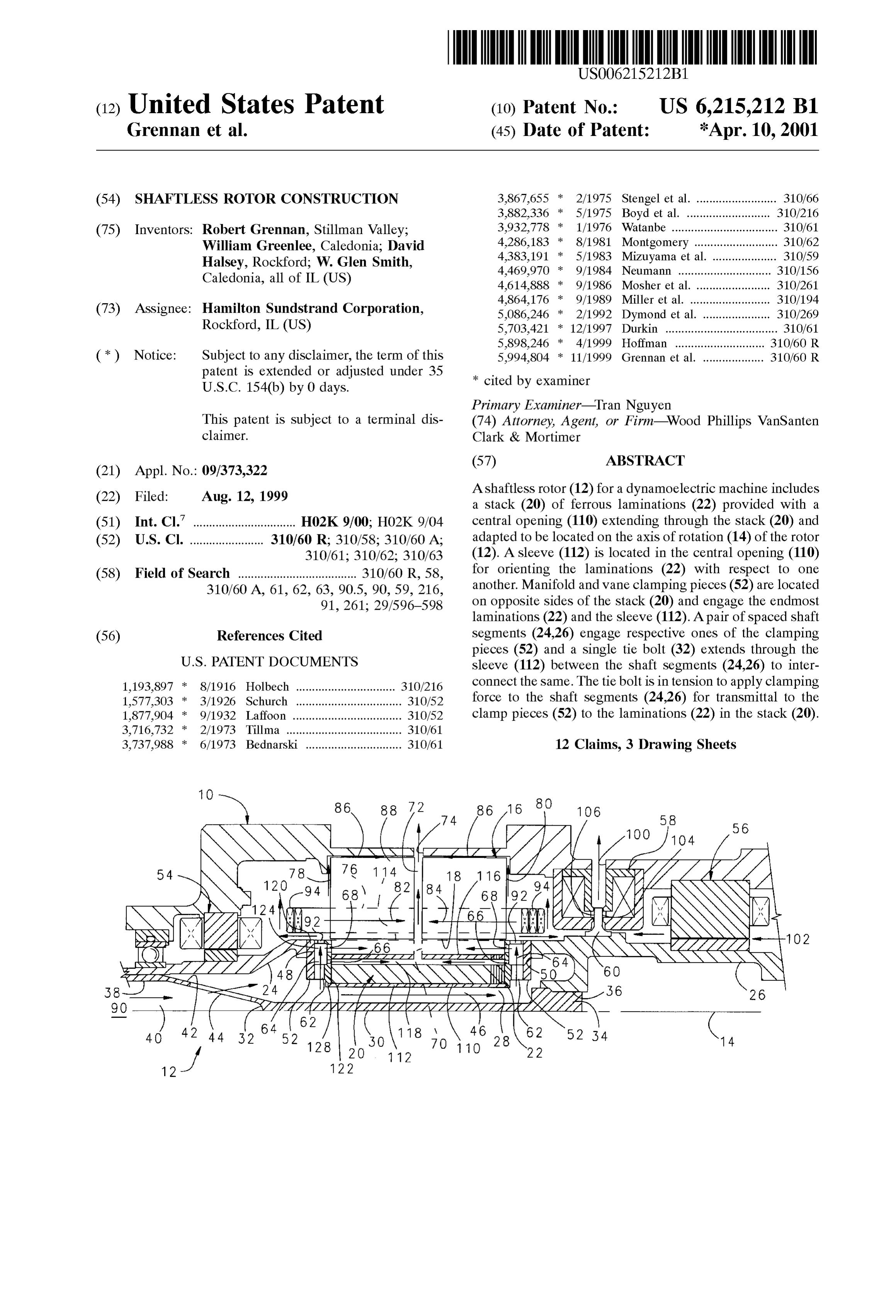
Ashaftless rotor (12) for a dynamoelectric machine includes (22) Filed Aug. 12, 1999 a stack (20) of ferrous laminations (22) provided with a (51) Int. Cl." ................................ H02K9/00; HO2K9/04 central opening (110) extending through the Stack (20) and (52) U.S. Cl. ....................... 310/60 R; 310/58; 310/60 A; adapted to be located on the axis of rotation (14) of the rotor 310/61; 310/62; 310/63 (12). A sleeve (112) is located in the central opening (110) (58) Field of Search ..................................... 310/60 R, 58 for orienting the laminations (22) with respect to one 310/60 A, 61, 62, 63, 90.5, 90,59 216. another. Manifold and Vane clamping pieces (52) are located s s/ -- was 9. 261. 29,596-59s on opposite sides of the Stack (20) and engage the endmost s a s/ us laminations (22) and the sleeve (112). A pair of spaced shaft (56) References Cited Segments (24.26) engage respective ones of the clamping pieces (52) and a single tie bolt (32) extends through the
1,193,897 8/1916 Holbech ............................... 310,216 connect the same. The tie bolt is intension to apply clamping 1577303 * 3/1926 Schurch ................................. 31.0/52 force to the shaft segments (24.26) for transmittal to the 1,877,904 9/1932 Laffoon .................................. 31.0/52 clamp pieces (52) to the laminations (22) in the stack (20). 3,716,732 2/1973 Tillma .................................... 310/61 3,737,988 6/1973 Bednarski .............................. 310/61 12 Claims, 3 Drawing Sheets
76N AN1 ANTS
a1a2.11a22 1 O2
2's VS22 52 34 (
Page 2
Drawing sheet — no readable text.
Page 3
Drawing sheet — no readable text.
Page 4
Drawing sheet — no readable text.
Page 5
SHAFTLESS ROTOR CONSTRUCTION orients the laminations with respect to one another. Clamp ing pieces are disposed on opposite ends of the Stack and
FIELD OF THE INVENTION engage the end most laminations in the Stack and the Sleeve. This invention relates to dynamoelectric machines, and A pair of Spaced Shaft elements, one at each end of the Stack, are provided to engage respective ones of the clamp pieces.
more particularly, to a shaftleSS rotor construction for use in The Shaft Segments are located on the rotational axis of the Such machines.
rotor. A Single tie bolt extends through the Sleeve between
BACKGROUND OF THE INVENTION the shaft Segments and interconnects the Same. The tie bolt is in tension to apply clamping force to the Shaft Segments
Dynamoelectric machines come in widely varying shapes, for transmittal through the clamp pieces to the laminations sizes and capacities. Some are employed as motors while in the Stack.
others are employed as generators. And Some are employed In one embodiment of the invention, the sleeve is cylin as combination motors-generators, meaning that they can be drical and includes an inner diameter Substantially larger operated either as a motor or as a generator, depending upon than the tie bolt So that an annular coolant passage exists exactly what function is desired of the machine at a given 15 between the sleeve inner diameter and the tie bolt and which point in time. extends from end to end of the lamination Stack. In Some cases, Volume and weight constraints are Preferably, the clamping pieces include fluid passages in minimal, while in others they are critical. For example, in fluid communication with the annular coolant passage. aerospace applications, weight is always a concern. Volume In a preferred embodiment, the fluid passages include constraints are also a concern lest the machine occupy too Vanes for pumping coolant from the annular coolant passage much space on an aircraft or even contribute to a leSS to both ends of the stack.
efficient aerodynamic shape as a result of its bulk. In one embodiment of the invention, the tie bolt is Most such machines have a shafted rotor which is to say enlarged and includes a chamber. The chamber has an inlet that a single shaft extends through the rotor body to journal 25 end adapted to be in fluid communication with a Source of the same for rotation about an axis within a Stator. This is, coolant and openings are located in the tie bolt to extend however, not always desirable. For example, in Some from the chamber to the exterior of the tie bolt for estab machines, the presence of a shaft extending through the rotor lishing fluid communication between the inlet end and the body may interfere with the magnetic flux path of the annular coolant passage.
machine and thus contribute to magnetic inefficiency which In a highly preferred embodiment, the tie bolt has a in turn may lower the capacity of a machine having a given reduced diameter central Section that is connected to the size. This is particularly true in dynamoelectric machines enlarged end by a frusto-conical Section. The openings are having a relatively Small number of poles on the rotor. In located in the frusto-conical Section. Such cases, it may be desirable to provide a shaftless rotor. According to another facet of the invention, a shaftleSS See, for example, commonly assigned U.S. Pat. No. 4,562, 35 rotor for a dynamoelectric machine is provided and includes 641 issued Jan. 7, 1986 to Mosher et al. In other cases, the a Stack of ferrous laminations having opposed ends. Means presence of a single Shaft may contribute to weight and/or are provided dictate enlargement of the rotor for a given application in a rotor body. toA align the laminations in the Stack to define that rotor components cannot be located in the area of the and has a first size. A opening central extends through the Stack tie bolt, having a central Section rotor occupied by the shaft. This in turn requires that Such 40 extending through the central opening is provided. The tie components be located elsewhere in the rotor which may bolt central Section has a Second size less than the first size increase its size in order to house the components and/or to define an annular coolant passage between the tie bolt may decrease magnetic efficiency as a result of locating Such central Section and the central opening. The rotor includes a components radially outward of the Shaft. In Such cases it would be desirable to provide a shaftless rotor for the 45 pair of Spaced shaft Segments, one at each end of the opposed ends of the Stack which are interconnected by the purpose of reducing weight and/or allowing the part of the tie bolt. The rotor that would otherwise be occupied by the shaft to be for the shaft tie bolt is in tension to provide a clamping force used for housing other rotor components to thereby reduce of the Stack to clampforthe
Segments transmission to the opposed ends laminations in the Stack in overall rotor size. It would also be desirable from the
Standpoint of reducing the mass of the rotating components 50 assembled relation.
of the dynamoelectric machine to enhance the ability of the machine A preferred embodiment envisions a dynamoelectric dynamoelectric machine to operate at high Speed. including a Stator having a rotor receiving opening and a rotor
The present invention is directed to providing Such a the rotor receiving construction Such as Set forth above disposed in opening. Means are provided for jour shaftleSS rotor for a dynamoelectric machine. nalling the Shaft Segments to journal the rotor within the SUMMARY OF THE INVENTION 55 StatOr.
Other objects and advantages will become apparent from
It is the principal object of the invention to provide a new the following specification taken in connection with the and improved shaftless rotor for use in a dynamoelectric accompanying drawings.
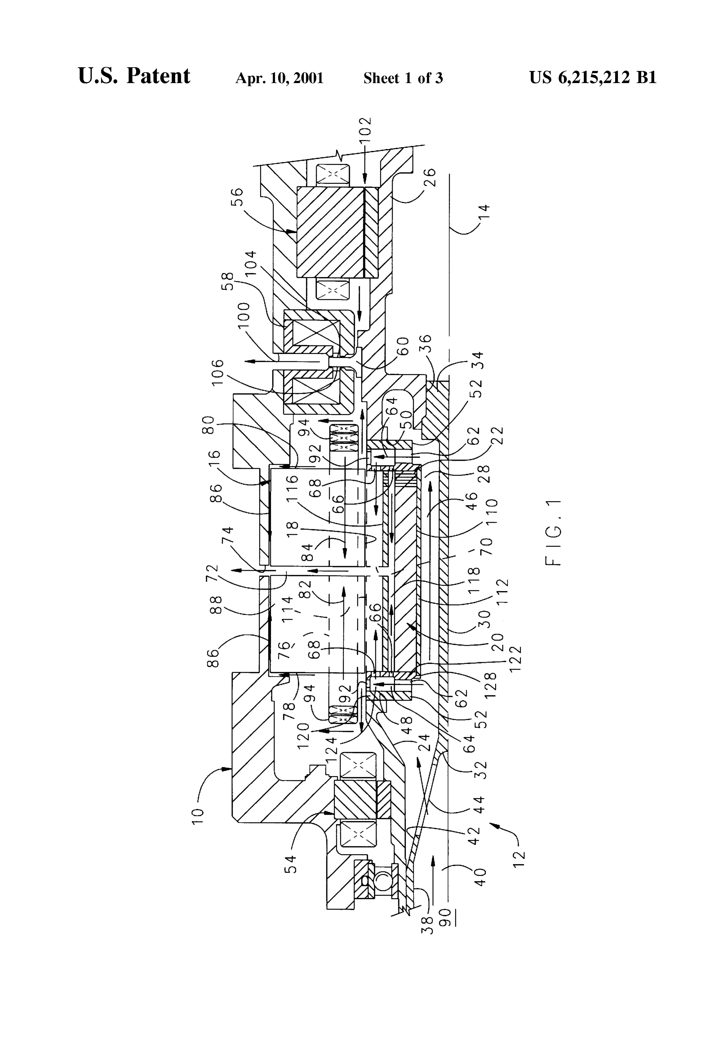
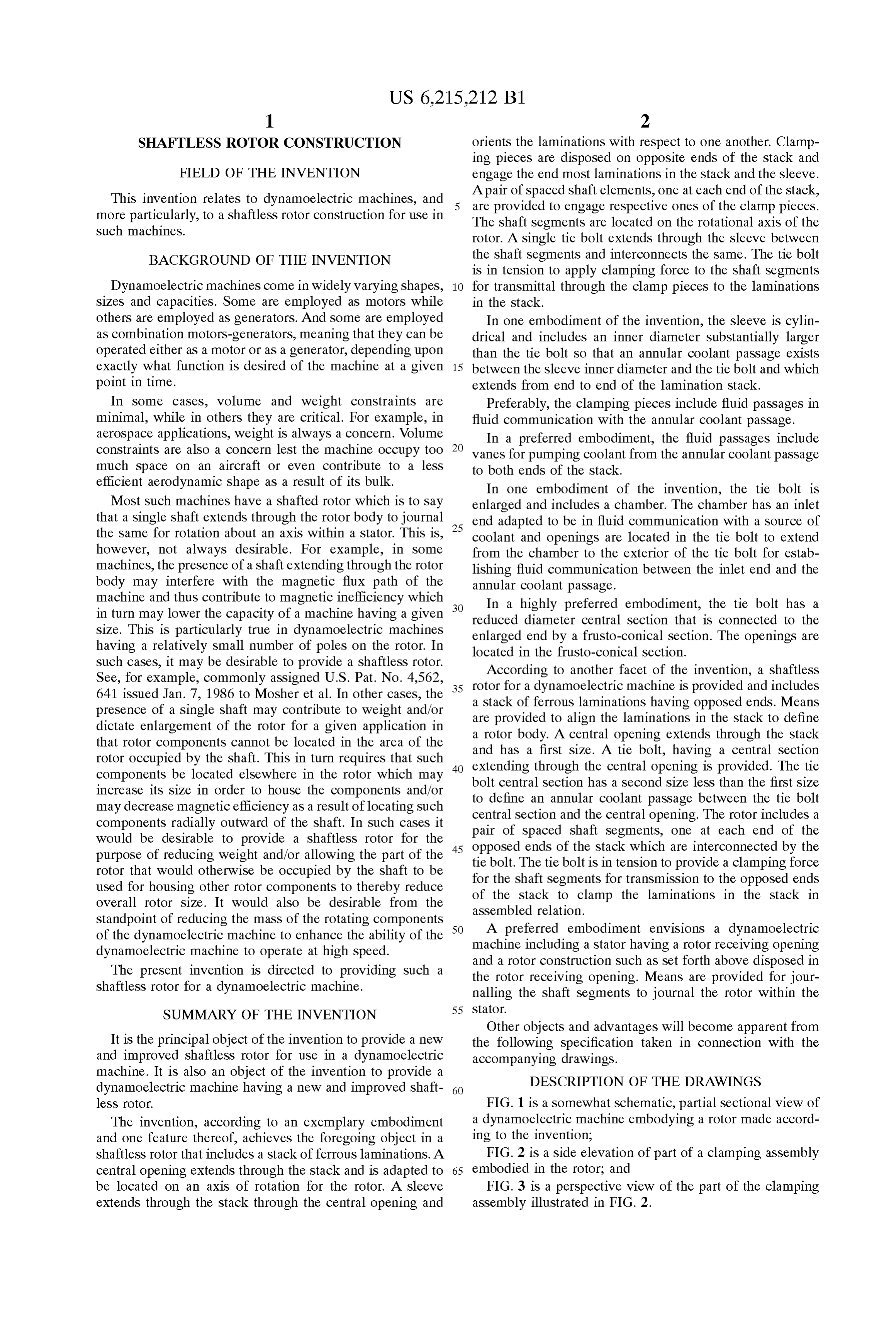
machine. It is also an object of the invention to provide a DESCRIPTION OF THE DRAWINGS dynamoelectric machine having a new and improved shaft 60 less rotor. FIG. 1 is a Somewhat Schematic, partial Sectional view of The invention, according to an exemplary embodiment a dynamoelectric machine embodying a rotor made accord and one feature thereof, achieves the foregoing object in a ing to the invention;
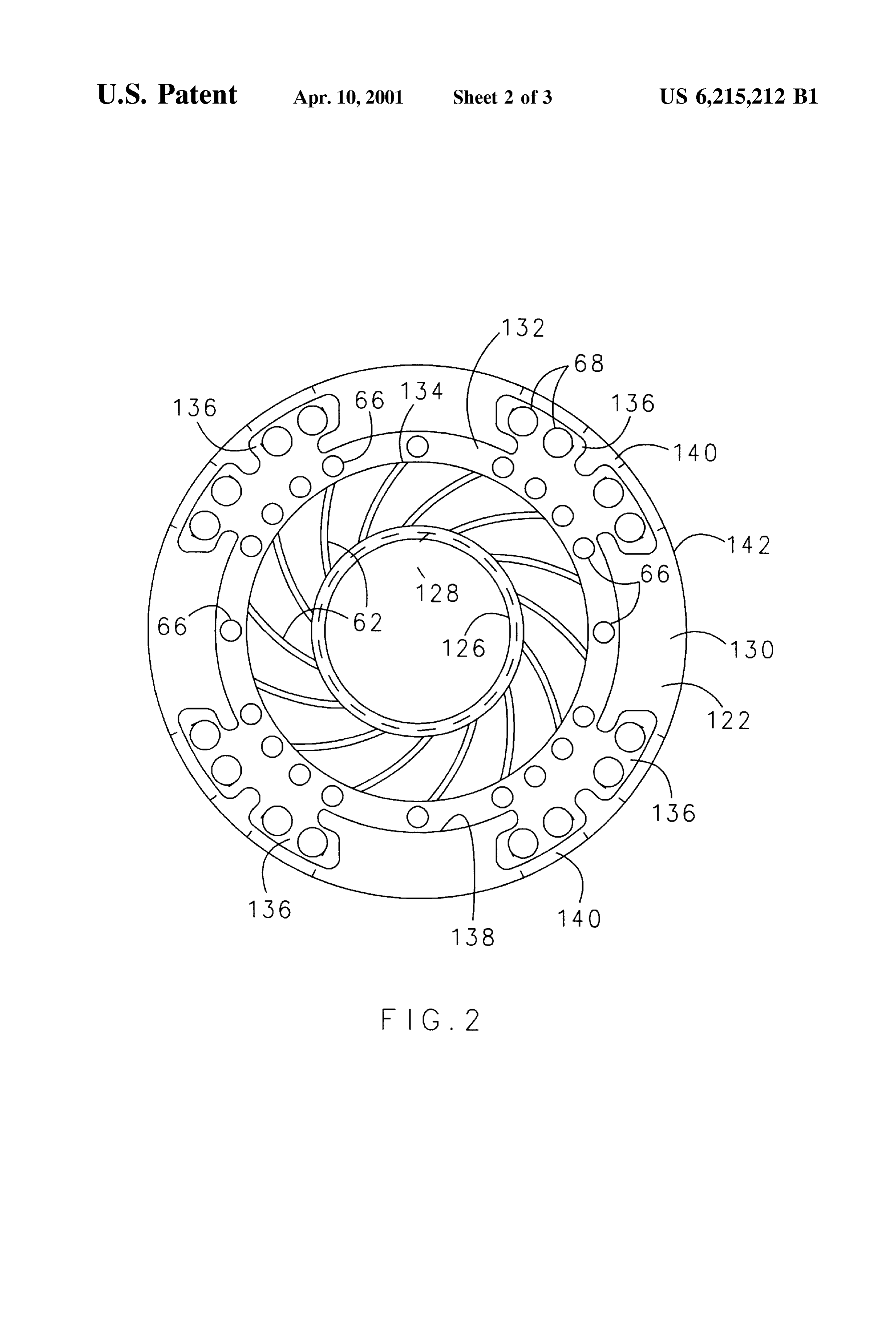
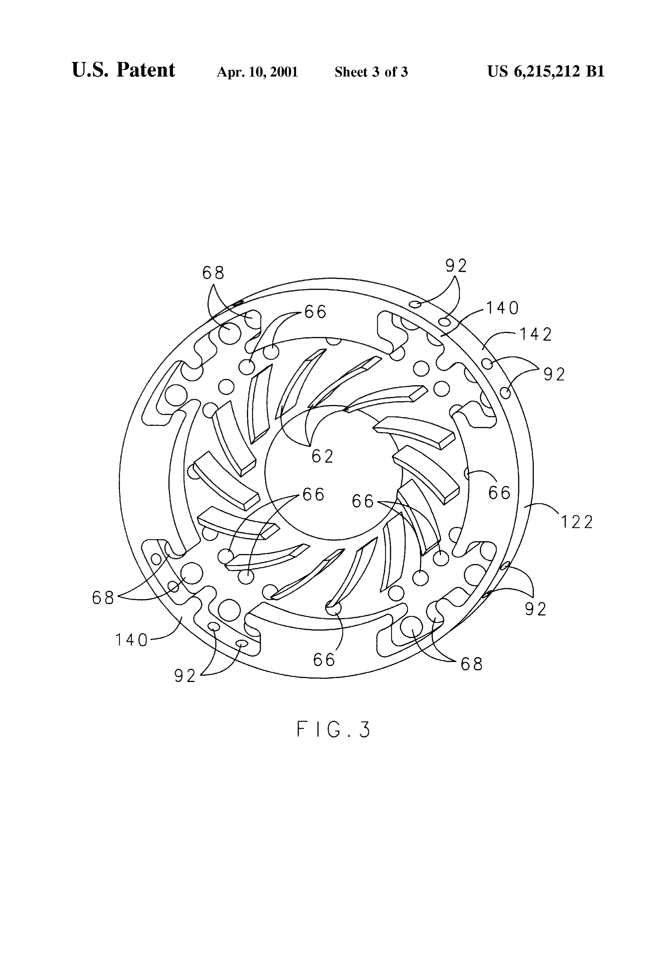
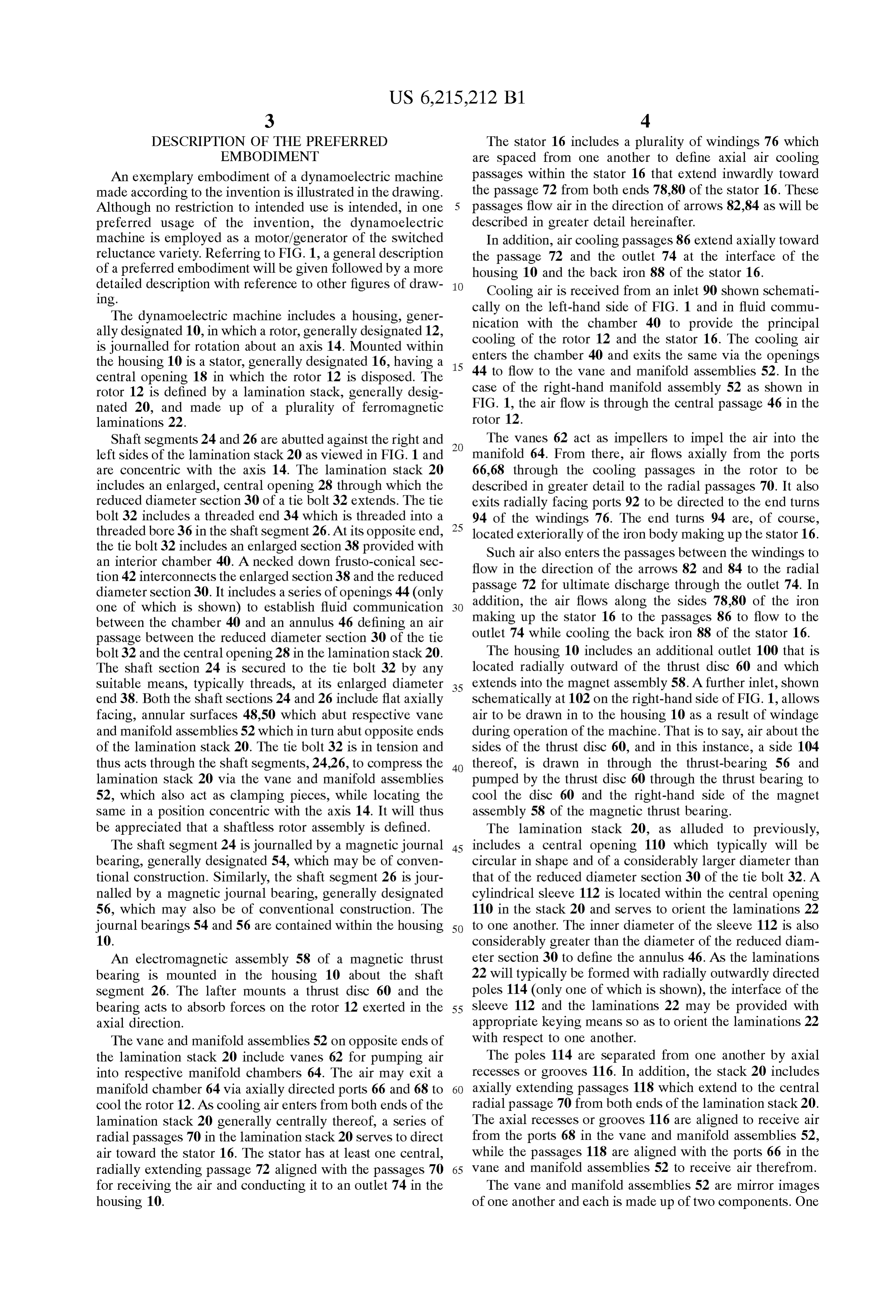
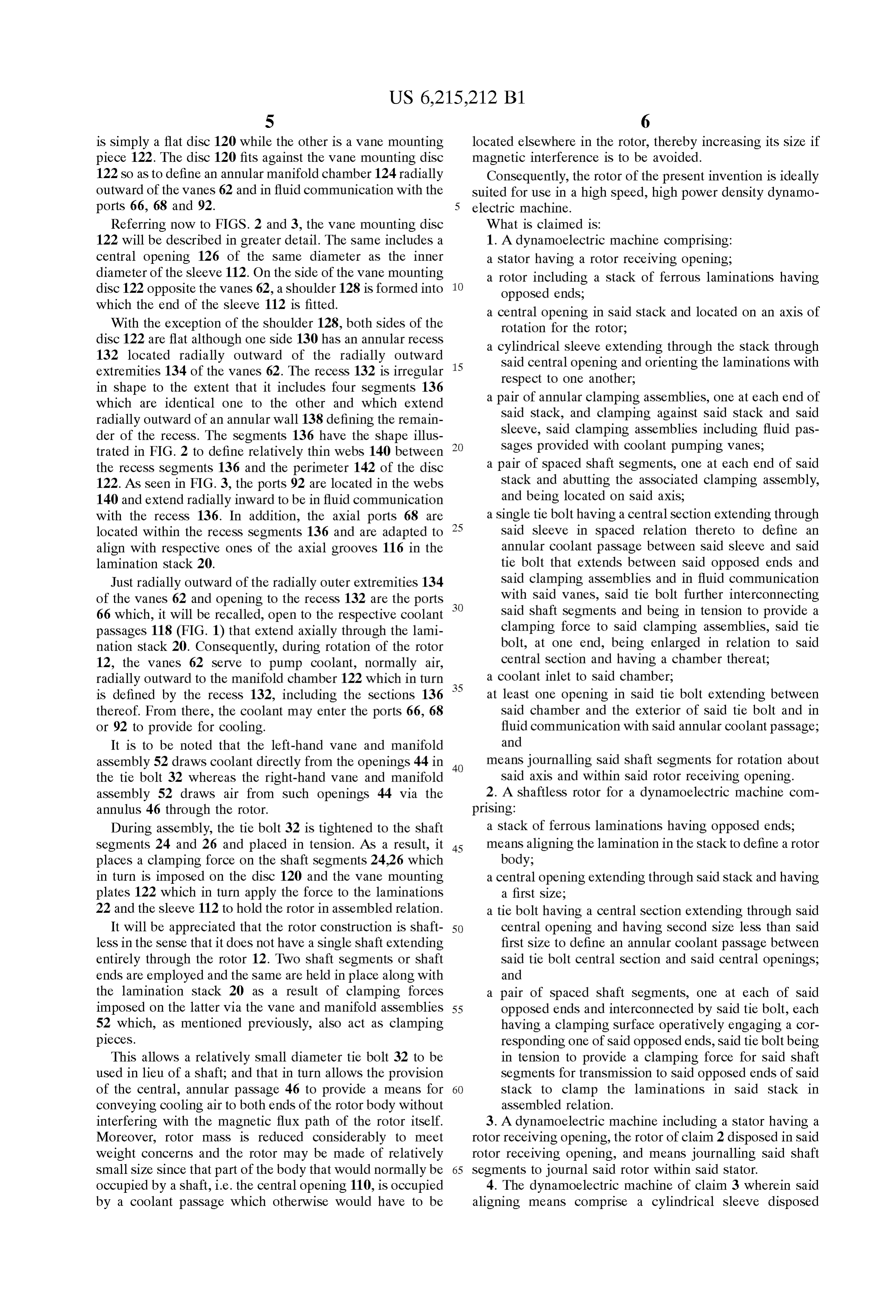
shaftleSS rotor that includes a Stack of ferrous laminations. A FIG. 2 is a side elevation of part of a clamping assembly central opening extends through the Stack and is adapted to 65 embodied in the rotor; and be located on an axis of rotation for the rotor. A sleeve FIG. 3 is a perspective view of the part of the clamping extends through the Stack through the central opening and assembly illustrated in FIG. 2.
Page 6
DESCRIPTION OF THE PREFERRED The stator 16 includes a plurality of windings 76 which EMBODIMENT are Spaced from one another to define axial air cooling An exemplary embodiment of a dynamoelectric machine passages within the Stator 16 that extend inwardly toward made according to the invention is illustrated in the drawing. the passage 72 from both ends 78.80 of the stator 16. These Although no restriction to intended use is intended, in one passages flow air in the direction of arrows 82.84 as will be preferred usage of the invention, the dynamoelectric described in greater detail hereinafter.
machine is employed as a motor/generator of the Switched In addition, air cooling passages 86 extend axially toward reluctance variety. Referring to FIG. 1, a general description the passage 72 and the outlet 74 at the interface of the of a preferred embodiment will be given followed by a more housing 10 and the back iron 88 of the stator 16. detailed description with reference to other figures of draw Cooling air is received from an inlet 90 shown schemati Ing.
The dynamoelectric machine includes a housing, gener cally on the left-hand side of FIG. 1 and in fluid commu nication with the chamber 40 to provide the principal ally designated 10, in which a rotor, generally designated 12, is journalled for rotation about an axis 14. Mounted within cooling of the rotor 12 and the stator 16. The cooling air enters the chamber 40 and exits the same via the openings the housing 10 is a Stator, generally designated 16, having a 15 44 to flow to the vane and manifold assemblies 52. In the central opening 18 in which the rotor 12 is disposed. The rotor 12 is defined by a lamination Stack, generally desig case of the right-hand manifold assembly 52 as shown in nated 20, and made up of a plurality of ferromagnetic FIG. 1, the air flow is through the central passage 46 in the laminations 22. rotor 12.
Shaft Segments 24 and 26 are abutted against the right and The vanes 62 act as impellers to impel the air into the left sides of the lamination stack 20 as viewed in FIG. 1 and manifold 64. From there, air flows axially from the ports are concentric with the axis 14. The lamination stack 20 66,68 through the cooling passages in the rotor to be includes an enlarged, central opening 28 through which the described in greater detail to the radial passages 70. It also reduced diameter section 30 of a tie bolt 32 extends. The tie exits radially facing ports 92 to be directed to the end turns bolt 32 includes a threaded end 34 which is threaded into a 94 of the windings 76. The end turns 94 are, of course,
threaded bore 36 in the shaft segment 26. At its opposite end, located exteriorally of the iron body making up the Stator 16. the tie bolt 32 includes an enlarged section 38 provided with Such air also enters the passages between the windings to an interior chamber 40. A necked down frusto-conical Sec flow in the direction of the arrows 82 and 84 to the radial tion 42 interconnects the enlarged Section 38 and the reduced diameter Section 30. It includes a Series of openings 44 (only passage addition, 72 for ultimate discharge through the outlet 74. In the air flows along the sides 78.80 of the iron one of which is shown) to establish fluid communication between the chamber 40 and an annulus 46 defining an air making up the Stator 16 to the passages 86 to flow to the passage between the reduced diameter Section 30 of the tie outlet 74 while cooling the back iron 88 of the stator 16. bolt 32 and the central opening 28 in the lamination stack 20. The housing 10 includes an additional outlet 100 that is The shaft section 24 is secured to the tie bolt 32 by any located radially outward of the thrust disc 60 and which Suitable means, typically threads, at its enlarged diameter 35 extends into the magnet assembly 58. A further inlet, shown end 38. Both the shaft sections 24 and 26 include flat axially schematically at 102 on the right-hand side of FIG. 1, allows facing, annular surfaces 48,50 which abut respective vane air to be drawn in to the housing 10 as a result of windage and manifold assemblies 52 which in turn abut opposite ends during operation of the machine. That is to Say, air about the of the lamination stack 20. The tie bolt 32 is in tension and sides of the thrust disc 60, and in this instance, a side 104 thus acts through the Shaft Segments, 24.26, to compress the 40 thereof, is drawn in through the thrust-bearing 56 and lamination stack 20 via the vane and manifold assemblies pumped by the thrust disc 60 through the thrust bearing to 52, which also act as clamping pieces, while locating the cool the disc 60 and the right-hand side of the magnet Same in a position concentric with the axis 14. It will thus assembly 58 of the magnetic thrust bearing. be appreciated that a ShaftleSS rotor assembly is defined. The lamination Stack 20, as alluded to previously, The shaft Segment 24 is journalled by a magnetic journal 45 includes a central opening 110 which typically will be bearing, generally designated 54, which may be of conven circular in shape and of a considerably larger diameter than tional construction. Similarly, the Shaft Segment 26 is jour that of the reduced diameter section 30 of the tie bolt 32. A nalled by a magnetic journal bearing, generally designated cylindrical sleeve 112 is located within the central opening 56, which may also be of conventional construction. The 110 in the stack 20 and serves to orient the laminations 22 journal bearings 54 and 56 are contained within the housing 50 to one another. The inner diameter of the sleeve 112 is also 10. considerably greater than the diameter of the reduced diam An electromagnetic assembly 58 of a magnetic thrust eter section 30 to define the annulus 46. As the laminations bearing is mounted in the housing 10 about the shaft 22 will typically be formed with radially outwardly directed segment 26. The lafter mounts a thrust disc 60 and the poles 114 (only one of which is shown), the interface of the bearing acts to absorb forces on the rotor 12 exerted in the 55 sleeve 112 and the laminations 22 may be provided with axial direction. appropriate keying means So as to orient the laminations 22 The vane and manifold assemblies 52 on opposite ends of with respect to one another.
the lamination Stack 20 include Vanes 62 for pumping air The poles 114 are separated from one another by axial into respective manifold chambers 64. The air may exit a recesses or grooves 116. In addition, the Stack 20 includes manifold chamber 64 via axially directed ports 66 and 68 to 60 axially extending passages 118 which extend to the central cool the rotor 12. As cooling air enters from both ends of the radial passage 70 from both ends of the lamination stack 20. lamination Stack 20 generally centrally thereof, a Series of The axial recesses or grooves 116 are aligned to receive air radial passages 70 in the lamination stack 20 serves to direct from the ports 68 in the vane and manifold assemblies 52, air toward the Stator 16. The Stator has at least one central, while the passages 118 are aligned with the ports 66 in the radially extending passage 72 aligned with the passages 70 65 vane and manifold assemblies 52 to receive air therefrom. for receiving the air and conducting it to an outlet 74 in the The Vane and manifold assemblies 52 are mirror images housing 10. of one another and each is made up of two components. One
Page 7
S 6 is simply a flat disc 120 while the other is a vane mounting located elsewhere in the rotor, thereby increasing its size if piece 122. The disc 120 fits against the Vane mounting disc magnetic interference is to be avoided. 122 so as to define an annular manifold chamber 124 radially Consequently, the rotor of the present invention is ideally outward of the vanes 62 and in fluid communication with the Suited for use in a high Speed, high power density dynamo ports 66, 68 and 92. 5 electric machine.
Referring now to FIGS. 2 and 3, the vane mounting disc What is claimed is:
122 will be described in greater detail. The same includes a 1. A dynamoelectric machine comprising: central opening 126 of the same diameter as the inner a Stator having a rotor receiving opening; diameter of the sleeve 112. On the side of the vane mounting a rotor including a Stack of ferrous laminations having disc 122 opposite the vanes 62, a shoulder 128 is formed into opposed ends, which the end of the sleeve 112 is fitted.
a central opening in Said Stack and located on an axis of
With the exception of the shoulder 128, both sides of the rotation for the rotor;
disc 122 are flat although one side 130 has an annular recess a cylindrical Sleeve extending through the Stack through 132 located radially outward of the radially outward Said central opening and orienting the laminations with extremities 134 of the vanes 62. The recess 132 is irregular 15 respect to one another;
in shape to the extent that it includes four Segments 136 a pair of annular clamping assemblies, one at each end of which are identical one to the other and which extend radially outward of an annular wall 138 defining the remain Said Stack, and clamping against Said Stack and Said der of the recess. The segments 136 have the shape illus sleeve, Said clamping assemblies including fluid pas trated in FIG. 2 to define relatively thin webs 140 between Sages provided with coolant pumping Vanes, the recess segments 136 and the perimeter 142 of the disc a pair of Spaced shaft Segments, one at each end of Said 122. As seen in FIG. 3, the ports 92 are located in the webs Stack and abutting the associated clamping assembly, 140 and extend radially inward to be in fluid communication and being located on Said axis, with the recess 136. In addition, the axial ports 68 are 25 a single tie bolt having a central Section extending through located within the receSS Segments 136 and are adapted to Said sleeve in Spaced relation thereto to define an align with respective ones of the axial grooves 116 in the annular coolant passage between Said Sleeve and Said lamination stack 20. tie bolt that extends between Said opposed ends and Just radially outward of the radially outer extremities 134 Said clamping assemblies and in fluid communication of the Vanes 62 and opening to the receSS 132 are the ports with Said Vanes, Said tie bolt further interconnecting 66 which, it will be recalled, open to the respective coolant Said shaft Segments and being in tension to provide a passages 118 (FIG. 1) that extend axially through the lami clamping force to Said clamping assemblies, Said tie nation Stack 20. Consequently, during rotation of the rotor bolt, at one end, being enlarged in relation to Said 12, the Vanes 62 serve to pump coolant, normally air, central Section and having a chamber thereat; radially outward to the manifold chamber 122 which in turn 35 a coolant inlet to Said chamber;
is defined by the recess 132, including the sections 136 at least one opening in Said tie bolt extending between thereof. From there, the coolant may enter the ports 66, 68 said chamber and the exterior of said tie bolt and in or 92 to provide for cooling. fluid communication with Said annular coolant passage; It is to be noted that the left-hand vane and manifold and assembly 52 draws coolant directly from the openings 44 in 40 means journalling Said Shaft Segments for rotation about the tie bolt 32 whereas the right-hand vane and manifold Said axis and within Said rotor receiving opening. assembly 52 draws air from such openings 44 via the 2. A shaftleSS rotor for a dynamoelectric machine com annulus 46 through the rotor. prising:
During assembly, the tie bolt 32 is tightened to the shaft a Stack of ferrous laminations having opposed ends, Segments 24 and 26 and placed in tension. As a result, it 45 means aligning the lamination in the Stack to define a rotor places a clamping force on the shaft Segments 24.26 which body;
in turn is imposed on the disc 120 and the Vane mounting a central opening extending through Said Stack and having plates 122 which in turn apply the force to the laminations a first size;
22 and the sleeve 112 to hold the rotor in assembled relation. a tie bolt having a central Section extending through Said It will be appreciated that the rotor construction is shaft 50 central opening and having Second Size less than Said leSS in the Sense that it does not have a Single Shaft extending first size to define an annular coolant passage between entirely through the rotor 12. Two shaft segments or shaft Said tie bolt central Section and Said central openings, ends are employed and the same are held in place along with and the lamination Stack 20 as a result of clamping forces a pair of Spaced shaft Segments, one at each of Said imposed on the latter via the Vane and manifold assemblies 55 opposed ends and interconnected by Said tie bolt, each 52 which, as mentioned previously, also act as clamping having a clamping Surface operatively engaging a cor pieces. responding one of Said opposed ends, Said tie bolt being This allows a relatively small diameter tie bolt 32 to be in tension to provide a clamping force for said Shaft used in lieu of a shaft, and that in turn allows the provision Segments for transmission to Said opposed ends of Said of the central, annular passage 46 to provide a means for 60 Stack to clamp the laminations in Said Stack in conveying cooling air to both ends of the rotor body without assembled relation.
interfering with the magnetic flux path of the rotor itself. 3. A dynamoelectric machine including a Stator having a Moreover, rotor mass is reduced considerably to meet rotor receiving opening, the rotor of claim 2 disposed in Said weight concerns and the rotor may be made of relatively rotor receiving opening, and means journalling Said shaft small size since that part of the body that would normally be 65 Segments to journal Said rotor within Said Stator. occupied by a shaft, i.e. the central opening 110, is occupied 4. The dynamoelectric machine of claim 3 wherein said by a coolant passage which otherwise would have to be aligning means comprise a cylindrical sleeve disposed
Page 8
within Said central opening, said sleeve having an inner a single tie bolt extending through Said Sleeve between diameter Substantially greater than Said Second size to define Said shaft Segments and interconnecting Said Shaft Said annular coolant passage. Segments, Said tie bolt being in tension to apply clamp 5. The shaftless rotor of claim 4 wherein one end of said ing force to Said Shaft Segments for transmittal through tie bolt is enlarged and includes a chamber, Said chamber Said clamping pieces to the laminations in Said Stack, having an inlet end adapted to be in fluid communication Said tie bolt being located on Said axis. with a Source of coolant, and openings in Said tie bolt 8. The shaftless rotor of claim 7 wherein said sleeve is extending from said chamber to the exterior of the tie bolt cylindrical and includes an inner diameter Substantially for establishing fluid communication between Said inlet end larger than Said tie bolt So that an annular coolant passage and Said annular coolant passage. exists between Said sleeve inner diameter and Said tie bolt 6. The shaftless rotor of claim 5 wherein said tie bolt has and which extends from end to end of Said Stack. a reduced diameter central Section connected to Said 9. The shaftless rotor of claim 8 wherein said clamping enlarged one end by a frusto-conical Section, and Said pieces include fluid passages in fluid communication with openings are located in Said frusto-conical Section. Said annular coolant passage.
7. A shaftleSS rotor for a dynamoelectric machine com 15 10. The shaftless rotor of claim 9 wherein said fluid prising: passages include Vanes for pumping coolant from Said a Stack of ferrous laminations, annular coolant passage to both sides of Said Stack. 11. The shaftless rotor of claim 8 wherein one end of Said a central opening extending through the Stack and located on an axis of rotation for the rotor; tie bolt is enlarged and includes a chamber, Said chamber having an inlet end adapted to be in fluid communication a sleeve extending through the Stack through Said central with a Source of coolant, and openings in Said tie bolt openings and orienting the laminations with respect to extending one another;
from said chamber to the exterior of the tie bolt for establishing fluid communication between Said inlet end clamping pieces on opposite ends of Said Stack and and Said annular coolant passage.
engaging the endmost lamination in the Stack and Said 25 12. The shaftless rotor of claim 11 wherein said tie bolt sleeve; has a reduced diameter central Section connected to Said a pair of Spaced shaft Segments, one at each end of Said enlarged one end by a frusto-conical Section, and Said Stack and engaging respective ones of Said clamp openings are located in Said frusto-conical Section. pieces, Said shaft Segments being located on Said axis, and k k k k k
Page 9
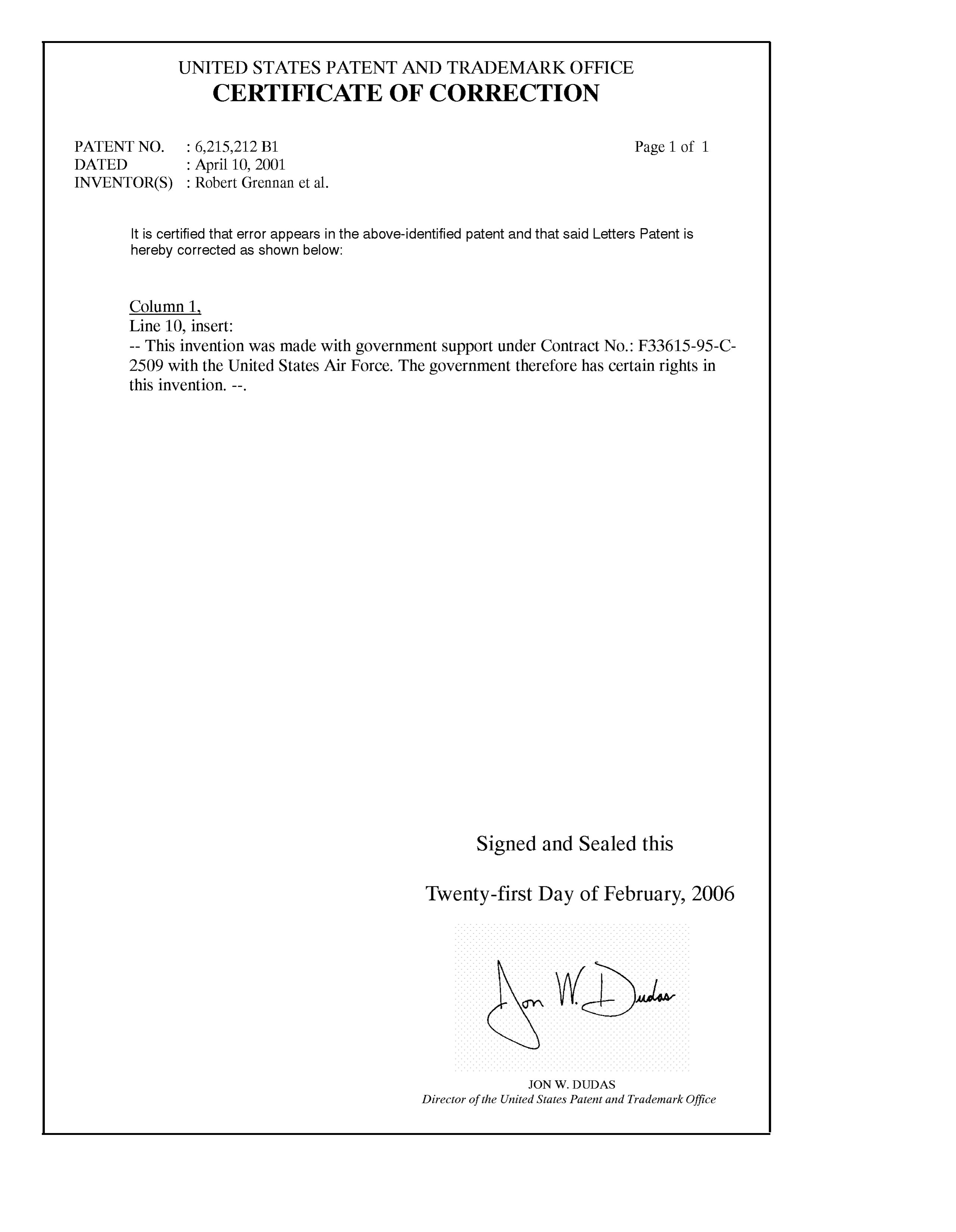
UNITED STATES PATENT AND TRADEMARK OFFICE
CERTIFICATE OF CORRECTION
PATENT NO. : 6,215,212 B1 Page 1 of 1
INVENTOR(S) : Robert Grennan et al.
It is certified that error appears in the above-identified patent and that said Letters Patent is hereby corrected as shown below:
Column 1
Line 10, insert:
-- This invention was made with government Support under Contract No.: F33615-95-C- 2509 with the United States Air Force. The government therefore has certain rights in this invention. --.
Signed and Sealed this
Twenty-first Day of February, 2006
WDJ
JON W. DUDAS
Director of the United States Patent and Trademark Office
Provenance
- Collection
- Cited prior art
- Original PDF
- patentimages.storage.googleapis.com →
- Filed
- 1999-08-12
- Pages
- 9
- Method
- pdftotext (the PDF's own text layer) + pdftoppm 300dpi page scans
- Source
- Google Patents bibliographic record
- Granted
- 2001-04-10
- Inventors
- Robert Grennan; William Greenlee; David Halsey; W. Glen Smith; Hamilton Sundstrand Corp
- Transcribed from
- patentimages.storage.googleapis.com →