patent · US6263868
Gas stove burner
24 July 2001
Page 1 — bibliographic record
(12) United States Patent (10) Patent No.: US 6,263,868 B1 K0ch et al. (45) Date of Patent: Jul. 24, 2001
(54) GAS STOVE BURNER FOREIGN PATENT DOCUMENTS (75) Inventors: Jirgen Koch, Attendorn (DE); Randy S. 3. s: Rummel, Huntington Beach; Dennis 78 156 11/1894 SE
Dacey, Long Beach, both of CA (US) 580 338 6/1933 (DE).
(73) ASSignee: AGT Gas Technology GmbH, OO81470 6/1983 SR Attendorn (DE) O485.645 5/1992 (EP).
(*) Notice: Subject to any disclaimer, the term of this 285 067 A 5/1928 (GB). patent is extended or adjusted under 35 1364890 * 8/1974 (GB).
U.S.C. 154(b) by 0 days. * cited by examiner (21) Appl. No.: 09/500,343 Primary Examiner Ira S. Lazarus ASSistant Examiner Josiah C Cocks (22) Filed: Feb. 8, 2000 (74) Attorney, Agent, or Firm-Herbert Dubno; Andrew (30) Foreign Application Priority Data Wilford
Feb. 9, 1999 (DE) .............................................. 199 OS 1.98 (57) ABSTRACT (51) Int. Cl. ................................. F24C3/00; F23Q 9/00 A gas Stove burner has a base having an annular outer edge (52) U.S. Cl. ..................... 126/39 R.s 126/39 E; 431/278
and a lower ring sitting on the base, forming therewith a lower compartment, and having an outer edge forming with (58) Field of Search 126/39R 39 B the base outer edge an outwardly open annular slot com 126/39 E; 431/354,350 258 264 266. municating with the lower compartment. An upper ring s 278 2so 285. 239f444 443 Sitting on the lower ring forms therewith an upper compart s s s s ment and has an outer edge forming with the lower-ring (56) References Cited outer edge an array of outwardly open holes communicating with the upper compartment. The upper-ring outer edge has
4,305,372 * 12/1981 Hahn 431/278 outer edge. Agas/air mixture is fed to each of the compart 4.886.043 12/1989 Homer". 129/39 R ments So that the gas will issue from the holes to form an 5,139,417 - 8/1992 Ghassemzadeh. ... its upper flame and from the slot to form a lower flame of 5,277,576 1/1994 Hartung et al. ....... 126/39 R Substantially the Same diameter. 5,639,232 * 6/1997 Bogenschutz et al. ... ... 431/354 5,765,542 * 6/1998 Fey et al. ........................... 126/39 E 7 Claims, 2 Drawing Sheets
9 Z 72 7 2
STSYYYYYYYYASNY a YANKS
Stras a ha// YAG-15
Ye Y
oSig Sex: Aege SS-20
24 3 É 27
straalaaa. S2%Nerf N-F-
Stés I SS
NNNNNeil
SSNS
Page 2
Drawing sheet — no readable text.
Page 3
Drawing sheet — no readable text.
Page 4
GAS STOVE BURNER the gas/air feed. Another inlet projects through the base and into the lower compartment between the central inlet and the
FIELD OF THE INVENTION lower-ring edge and is also connected to the gas/air feed. The present invention relates to a burner. More particu The gas Supply connected to the inlets includes indepen larly this invention concerns a gas burner for a cook Stove. dently operable and closable valves for feeding Separate flows of a gas/air mixture to the compartments So that either
BACKGROUND OF THE INVENTION of the flows can be completely cut off to completely elimi A high-quality Stove gas burner typically can produce a nate the respective flame. Thus the upper cooking flame can relatively large main flame and a Smaller warming flame. be used independently or in addition to the lower warming The latter is normally Set Such that it cannot exceed a certain flame, and the lower warming flame can be used alone. size, So that it can be used for Simmering or warming but is The edges of the rings and base are all of generally the not really powerful enough for most cooking procedures. Same diameter So that the flames are also of generally the The main flame is produced from nozzles that have an Same diameter. In addition the rings are circular and the overall flow croSS Section that is much greater than the 15 lower-ring Outer edge has an upwardly flaring frustoconical nozzles forming the warming flame. Typically the warming upper Surface. The upper ring outer edge has a complemen flame produces about 20% to 25% as much heat as the main tary and parallel lower Surface Spaced from the lower-ring flame. upper Surface and forming the slot therewith. The rings are In Some Systems the warming flame is centered in the circular and the upper-ring outer edge has a downwardly burner and in this case it can be even Smaller, between 10% directed lower Surface engaging an upwardly directed upper and 12% of the overall burner capacity. While this is very Surface of the lower-ring outer edge and formed with an handy for most applications, the centered position of this array of downwardly open notches forming the holes. flame creates a hot Spot in the center of the cooking utensil BRIEF DESCRIPTION OF THE DRAWING Sitting on the burner, and in fact food can be burnt because of this concentrated location even in Spite of the Small size 25 The above and other objects, features, and advantages will of the flame. Another disadvantage with this System is that become more readily apparent from the following a Separate igniter must often be provided for the central description, reference being made to the accompanying flame, adding to the cost of the burner, and in general Such drawing in which:
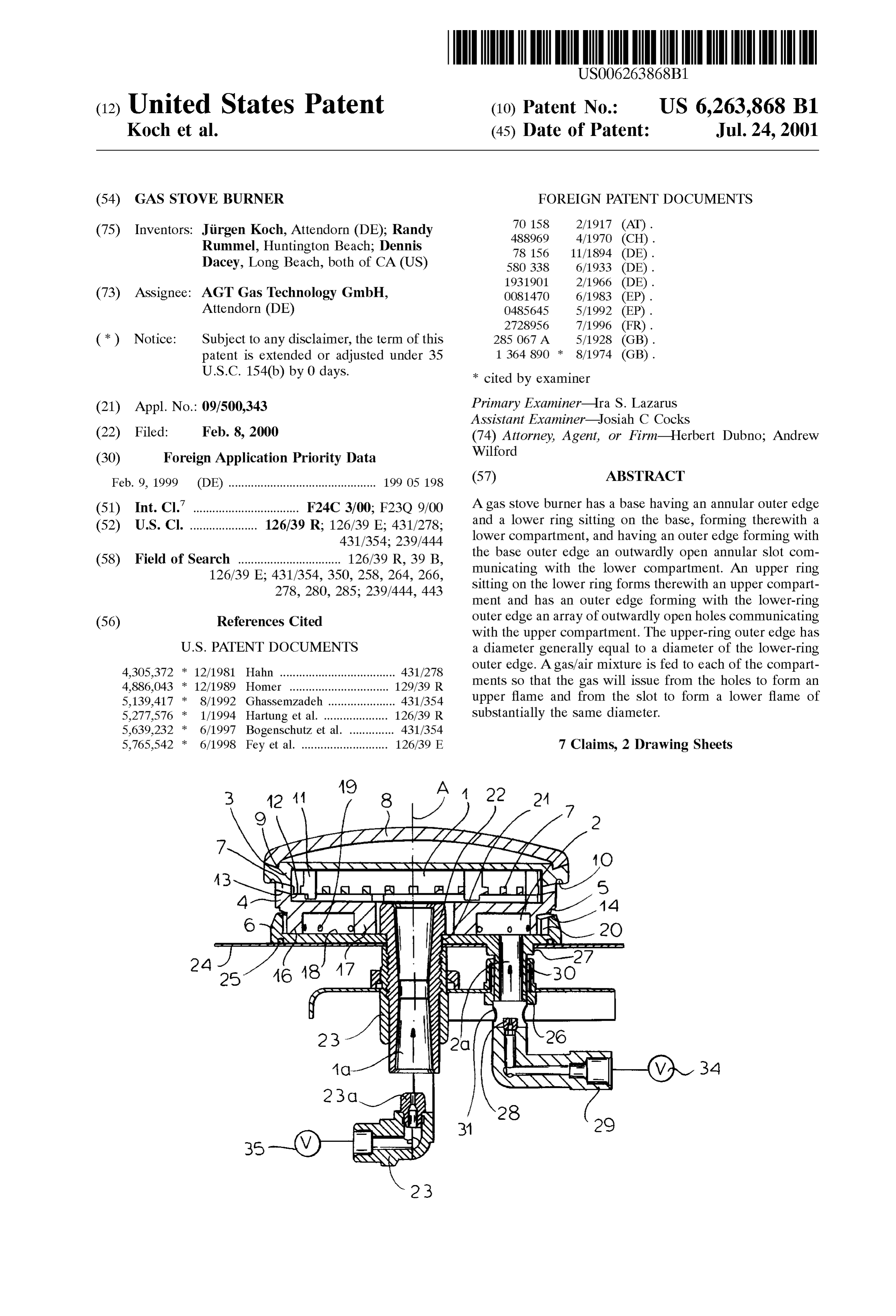
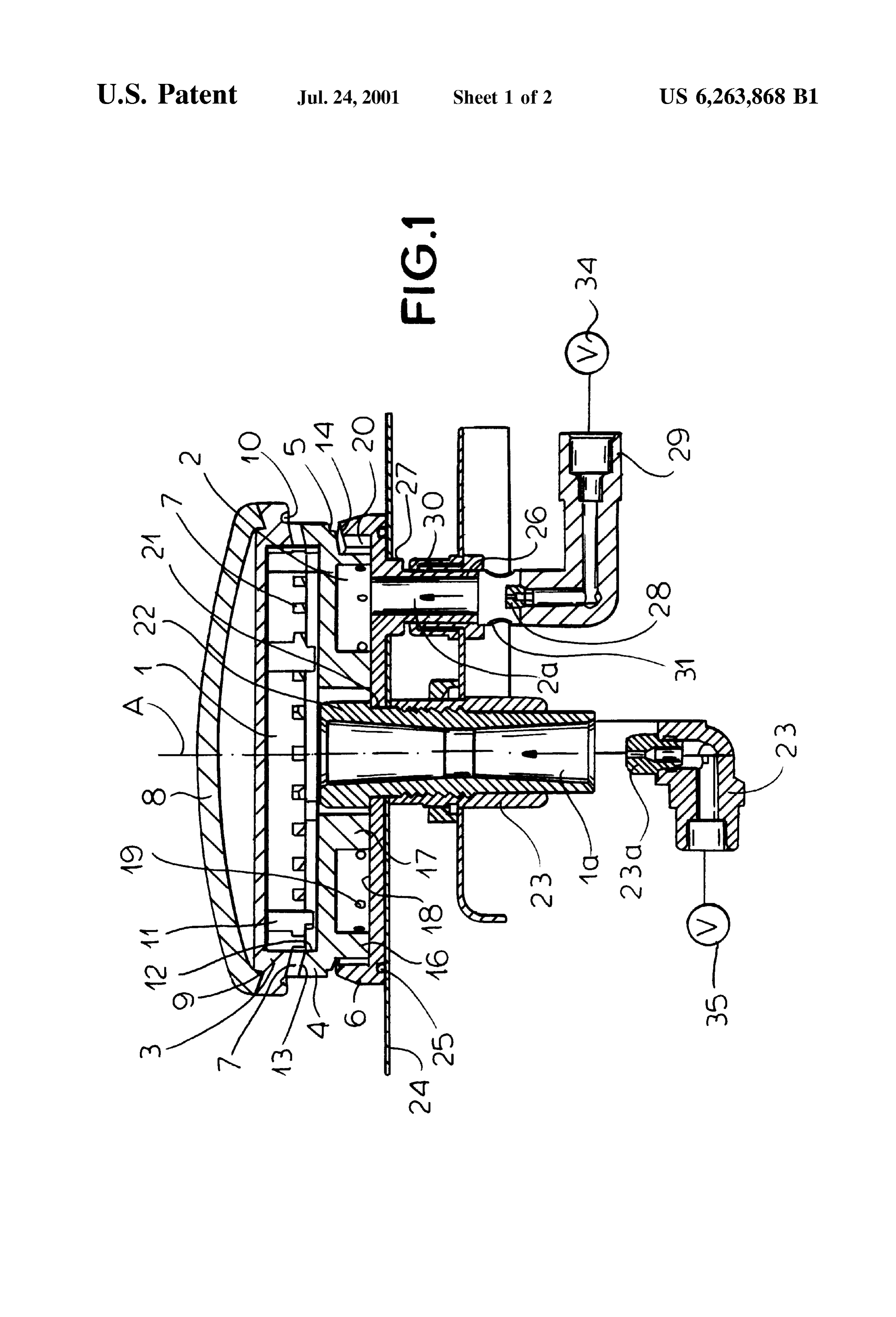
a dual-flame burner can be quite complex. FIG. 1 is a partly diagrammatic vertical Section through OBJECTS OF THE INVENTION the burner according to the invention;
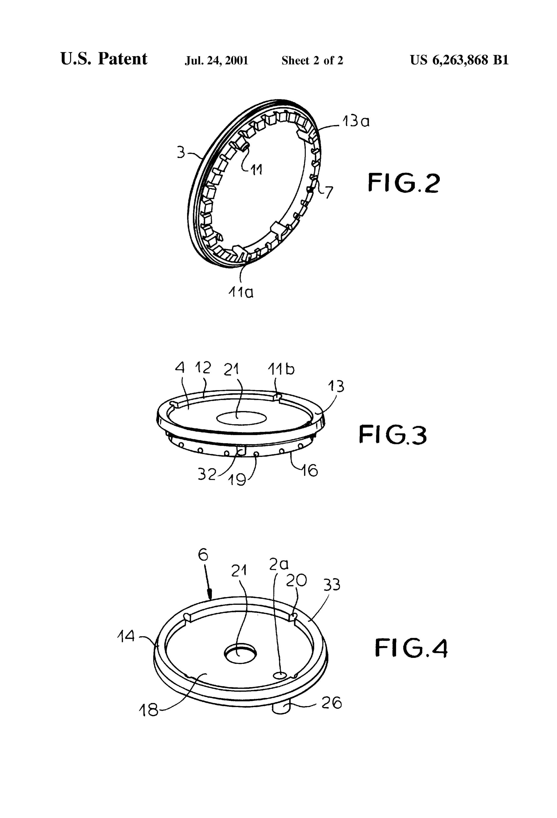
It is therefore an object of the present invention to provide of FIG. 2 is a perspective view from below of the upper ring the burner;
an improved gas Stove burner.
Another object is the provision of Such an improved gas FIG. 3 is a perspective view from above of the lower ring Stove burner which overcomes the above-given 35 the burner; and of disadvantages, that is which has low-heat warming flame FIG. 4 is a perspective view from above of the base plate whose effect is spread out, and which is of Simple construc of the burner.
tion.
SPECIFICDESCRIPTION
SUMMARY OF THE INVENTION
40 AS Seen in FIG. 1 a burner according to the invention is
A gas Stove burner has according to the invention a base centered on a vertical axis A and basically comprises a having an annular outer edge and a lower ring sitting on the circular base plate 6 Sitting on a Surface 24 of a Stove, a base, forming therewith a lower compartment, and having an lower ring 4 sitting on the base plate 6, an upper ring 3 outer edge forming with the base Outer edge an outwardly Sitting on the lower ring 4, and a cover plate 8 atop the upper open annular slot communicating with the lower compart 45 ring 3. An inlet 1a comprised of an axially centered feed tube ment. An upper ring sitting on the lower ring forms there 22 set in a central hole 21 of the ring 4 fits in a socket tube with an upper compartment and has an Outer edge forming 23 of the Stove and is Supplied with an air-gas mixture from with the lower-ring outer edge an array of outwardly open a nozzle 23a of a supply fitting 23. Another inlet 2a offset holes communicating with the upper compartment. The from the axis A is comprised of a tubular nipple 26 fitting in upper-ring Outer edge has a diameter generally equal to a 50 a tube 30 mounted on the stove and having a blender 31 and diameter of the lower-ring outer edge. A gas/air mixture is a nozzle 28 connected to another Supply fitting 29 for Supply fed to each of the compartments So that the gas will issue of an air/gas mixture. The nipple 26 has an enlarged upper from the holes to form an upper flame and from the slot to end 27 that fits in a complementary hole in the stove surface form a lower flame of Substantially the same diameter. 24 to lock the burner in place against rotation about the axis Thus with this system the warming flame is of the same 55 A. An O-ring 25 Set in the base plate 6 engages the Stove diameter as the cooking flame. The heat it produces will Surface 24 to prevent Spills or the like from getting under the therefore be spread out over the pot on the burner for burner.
effective warming or Simmering without any dangerous hot The top ring 3 as also shown in FIG. 2 has a frustoconical spots. What is more the provision of the warming flame and upwardly flaring lower edge 13a formed with a uniform below the cooking flame allows it to be used to ignite the 60 array of downwardly open hole-forming notches 7 that open cooking flame, and Vice versa, So that the construction of the into an upper compartment 1 defined between the ringS3 and burner is greatly simplified. The propagation of the warming 4 and into which the upper end of the inlet 1a also opens. flame through a gap has the advantage that it will ignite fully Immediately above the notches 7 the ring 3 is formed with and Stay ignited, as opposed to the problems of trying to a downwardly directed annular flame-diverting notch 10. keep a plurality of weak jets illuminated. 65 The floor of this compartment 1 is defined by an upper According to the invention a central inlet projects through Surface of the lower ring 4 which has an upwardly flaring the base and into the upper compartment and is connected to outer-edge upper Surface 13 (FIG. 3) complementary to the
Page 5
Surface 13a and engaging Same in Surface contact. Inwardly the base outer edge an outwardly open annular slot directed tabs 11 and 11a of the upper ring 3 fit in notches 11b communicating with the lower compartment; of an inner Surface 12 of the lower ring to center the upper an upper ring Sitting on the lower ring, forming there with ring 3 in the lower ring 4 and prevent the upper ring 3 from an upper compartment, and having an outer edge form rotating about the axis A in the lower ring 4. One of the tabs ing with the lower-ring outer edge an array of out 11a and the respective notch 11b are wider than the other Wardly open holes communicating with the upper tabs 11 so as to define one position only for the two parts 3 compartment, the upper-ring outer edge having a diam and 4 to fit together. The cover disk 8 is upwardly convexly eter generally equal to a diameter of the lower-ring rounded and fits with a rim 9 in a groove at the outer edge Outer edge; and of the upper ring 3 to hold it on center. means including respective independently operable and The lower ring as also shown in FIG. 3 has a pair of closable valves connected to the compartments for downwardly directed cylindrical webs 16 and 17 defining feeding respective gas/air mixtures to the compart with an upper surface 18 of the base plate 6 an annular lower ments Such that when both valves are open the gas will compartment 2 into which the inlet 2a opens. An array of issue from the holes to form an upper flame and from angularly equi-spaced and radially throughgoing holes 19 in 15 the slot to form a lower flame of Substantially the same diameter and when either of valves is closed the the outer web 16 direct the air/gas mixture in the lower respective flow is completely cut off to completely compartment 2 into the gap between a lower Surface 14 of eliminate the respective flame. the outer edge of the lower ring 4 and an upper Surface 33
(FIG. 4) of the outer edge of the base plate 6. The two 2. The gas stove burner defined in claim 1, further surfaces 14 and 33 together form an outwardly and upwardly comprising open lower-flame gap 5 below the holes 7. Radially out a central inlet projecting through the base and into the Wardly projecting lugs 32 formed on the lower ring 4 fit in upper compartment and connected to the gas/air feed
complementary inwardly open notches 20 of the base plate 6 to center the ring 4 and prevent it from rotating. 3. The gas stove burner defined in claim 2, further comprising
Thus when a valve 34 connected to the compartment 2 is 25 an inlet projecting through the base and into the lower opened, a gas/air mixture created at the blender 31 will flow compartment between the central inlet and the lower out the holes 19 and thence emerge as an annular radially ring edge and connected to the gas/air feed means. outwardly directed sheet from the gap 5. When ignited, the resultant flame can be adjusted down to a very low level for Valves 4. The gas stove burner defined in claim 3 wherein the Simmering or warming Something sitting above the burner. are connected to the inlets. When a valve 35 connected to the compartment 1 and edges are gas 5. The stove burner defined in claim 1 wherein the all of generally the Same diameter, whereby the operable independently of the valve 34 is opened a substan flames are also of generally the same diameter. tially greater flow of gas will issue from the notch holes 7, 6. The gas stove burner defined in claim 1 wherein the as the overall flow cross section of the notch holes 7 is 35 rings are greater than that of the gap 5. If the lower flame is burning, upwardly flaringcircular and the lower-ring outer edge has an frustoconical upper Surface, the upper ring it will automatically ignite these flows from the holes 7. The outer edge having a complementary and parallel lower upper flame is Substantially more robust than the lower one Surface Spaced from the lower-ring upper Surface and form and can be used individually for cooking and even in combination with the lower flame. Either flame can be used 40 ing the slot therewith.
independently and both together give a burner of consider rings 7. The gas stove burner defined in claim 1 wherein the able capacity. are circular and the upper-ring outer edge has a We claim:
downwardly directed lower Surface engaging an upwardly 1. A gas Stove burner comprising: directed upper Surface of the lower-ring outer edge and formed with an array of downwardly open notches forming a base having an annular outer edge; 45 the holes.
a lower ring sitting on the base, forming therewith a lower compartment, and having an Outer edge forming with
Provenance
- Collection
- Cited prior art
- Original PDF
- patentimages.storage.googleapis.com →
- Filed
- 2000-02-08
- Pages
- 5
- Method
- pdftotext (the PDF's own text layer) + pdftoppm 300dpi page scans
- Source
- Google Patents bibliographic record
- Granted
- 2001-07-24
- Inventors
- Jürgen Koch; Randy Rummel; Dennis Dacey; AGT Gas Technology GmbH
- Transcribed from
- patentimages.storage.googleapis.com →