patent · US2298663
Gas turbine plant
13 October 1942
Page 1
Drawing sheet — no readable text.
Page 2
Drawing sheet — no readable text.
Page 3
Patented Oct. 13, 1942 2,298,663
UNITED STATES PATENT OFFICE
GASTURBINE PLANT
walter Traupel, winterthur, Switzerland, assign or to Sulzer Frères, Société Anonyme, Winter thur, Switzerland
Application June 26, 1940, Serial No. 342,424
In Switzerlan June 28, 1939
This invention relates to an improved gas tur in at least two stages, it is preferable to allow bine plant and has for its object the provision of the working medium to do the work necessary for an improved gas turbine plant comprising a tur compressing in a first stage and after an inter bine, preferably a high pressure turbine, arranged mediate heating to use it in a second stage for to drive a turbo compressor, and a combustion developing power to be delivered outside the tur heating device constructed and arranged to heat bine. A gas turbine, plant according to the in a part of the air compressed in the turbo com vention may preferably be extended by a super pressor by combustion in a combustion space and charging group consisting of a turbine and a means to pass the other part of the compressed blower, this turbine being supplied with working air in heat exchange contact with the gas of O energymedium which has already given up part of its combustion to cool the gas and heat the air. The to produce useful mechanical energy. The apparatus includes means for utilizing the com two parts of the working medium are preferably bustion gas and compressed air from the heat changer.led in counter-current through the heat ex exchanger to drive separate high pressure turbine The invention also makes it possible to free the blades or to drive separate expansion turbines. 15 combustion gas from impurities in a dust collector The high pressure turbine is preferably ar ranged to pass the expanded gas therefrom since changer theat combustion
gases temperature leavewillthenotheat which
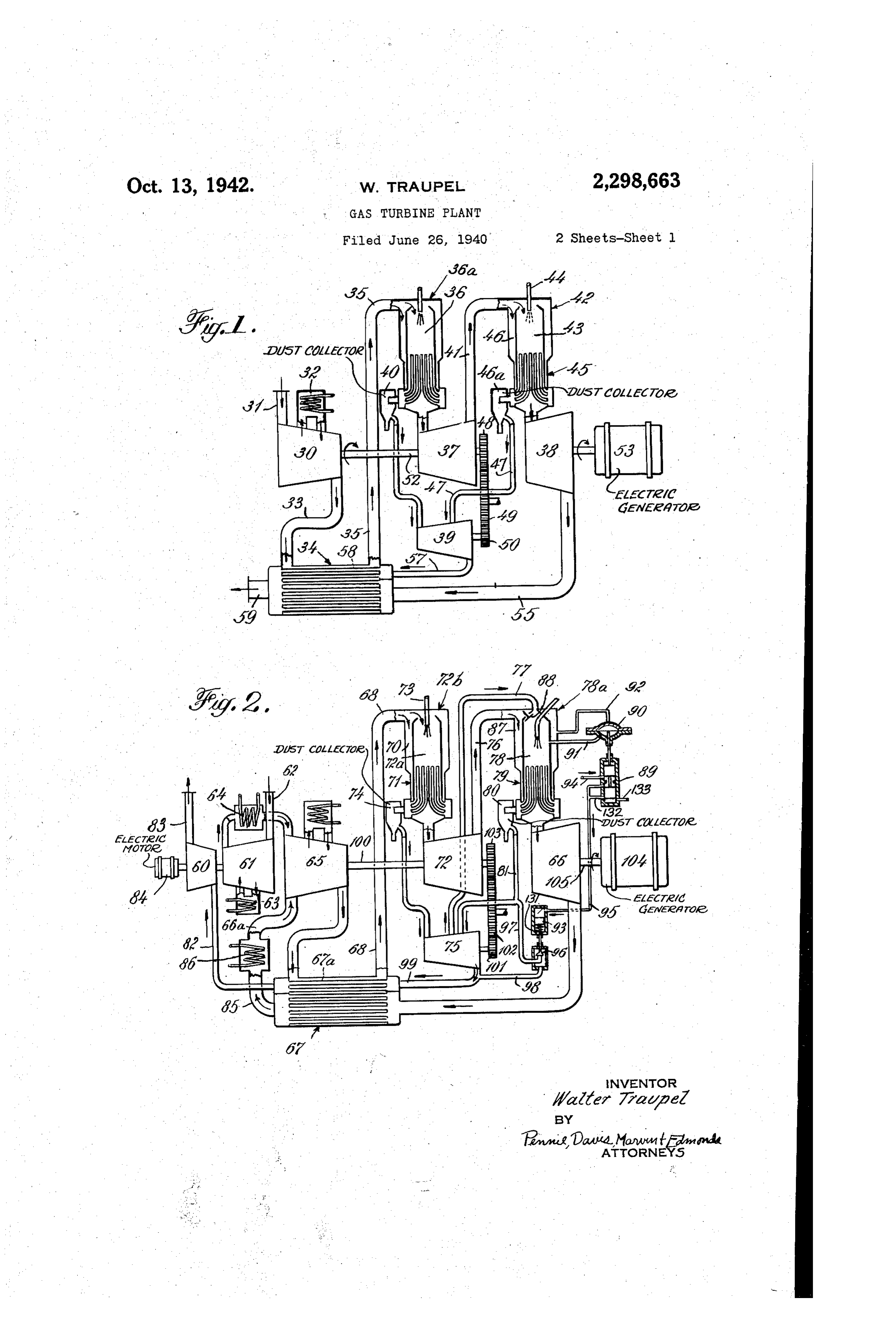
damage through combustion means and to a low pressure the dust collector. It is possible to pass the turbine which drives the load. The heating de vice preferably includes a heat exchanger ar 20 greater part of the working medium through the plant as pure air, so that the important parts of ranged between the combustion space and the the plant, particularly the turbines and ex turbine, preferably of such dimensions that sufi changers, are protected from dust. Dividing the cient of the heat of the gas from the combustion space (combustion gas) is transmitted to the air 25 working medium into one part that is led through the combustion space, and into another part that passed in heat exchange relation thereto that the does not take part in the combustion, also makes air and gas have practically the same temperature it possible to pass the combustion gases through at the outlet from the heat exchanger. the plant separately from the pure air, so that The invention aims to provide a gas turbine plant comprising a heating device arranged to Suitable adopted machines and heat exchangers may be for the combustion gases. In addition to receive gas discharged from a high pressure tur 30 that, the Working medium not taking part in the bine, to heat a part of the gas in combustion and combustion may be used again after being re to pass the remaining part of the gas in heat cooled in the plant, so that the compression exchange relation to the combustion gas, and a energy still contained in it may be utilized. low pressure turbine arranged to be driven by the gas from the heating device. In addition to the 35 lessThediagrammatically accompanying drawings illustrate more or apparatus embodying the aforementioned plant arrangements the inven tion contemplates the provision of an exhaust gas invention, in which:
turbine, with or without auxiliary motor power, Fig. 1 shows an example in which the portion driving a Supercharging blower arranged to of the Working medium heated in the combustion charge air into the inlet side of the turbo-com 40 chamber are and the portion heated by heat exchange expanded separately in separate turbines;
preSSOr. It is advantageous to provide means for Fig. 2 shows another example in which there is passing the combustion gas from the heating de E. provided a separate Supercharging turbo vices to a gas turbine which is operatively coupled unit;
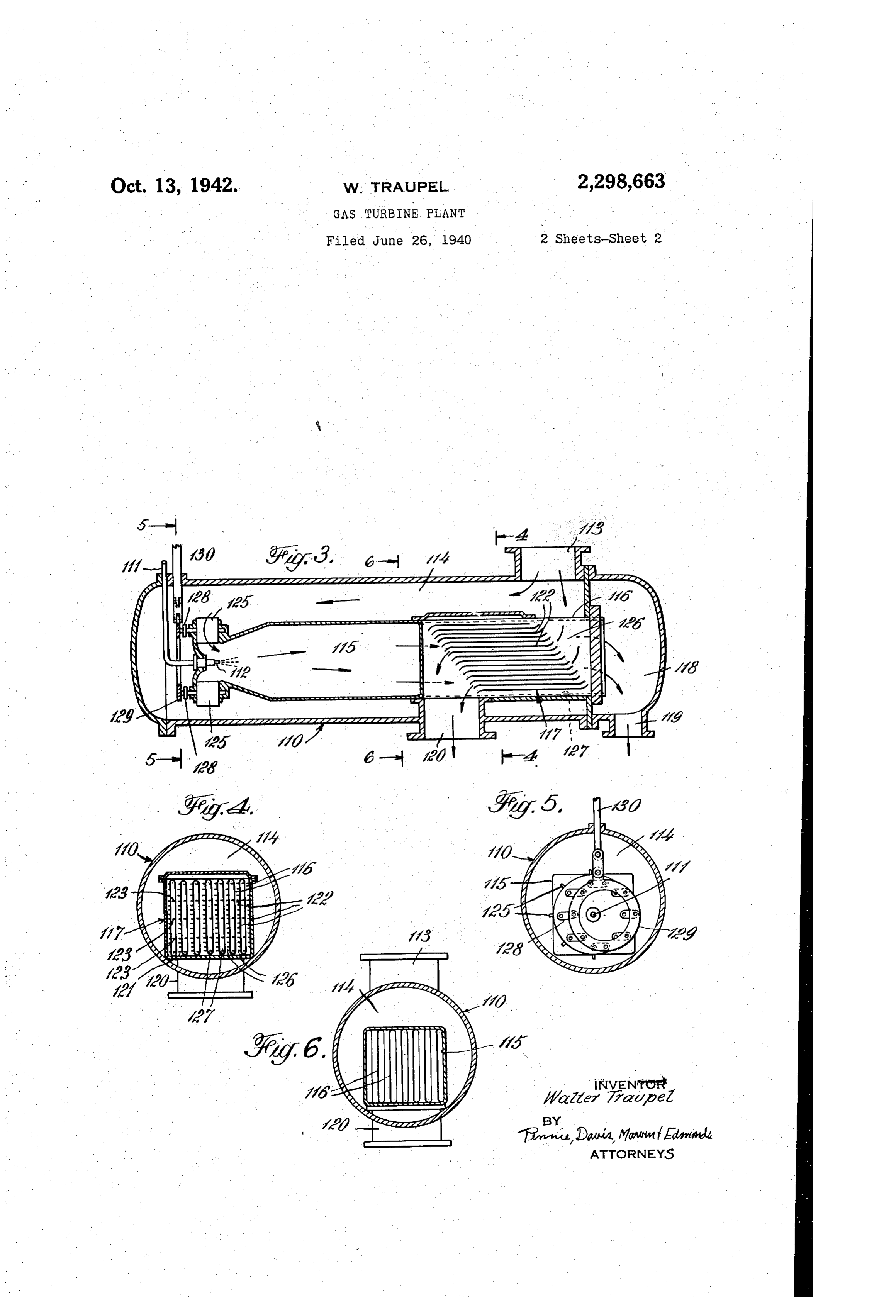
to the high pressure turbine, and the other part 45 Fig. 3 illustrates, on an enlarged scale, a sec of the gas or heated air to high and low pressure tional view of a heating device; turbines. Fig. 4 is a section through 4-4 in Fig. 3; Apparatus is also provided to pass a part of the Fig. 5 is a section through 5-5 in Fig. 3; and combustion gas expanded in a special turbine to Fig. 6 is a section through 6-6 in Fig. 3. another combustion space. The gas from the In the plant illustrated in Fig. 1, the turbo said combustion space is passed to a heat ex compressor 30 draws in air through opening 3 changer and in heat exchange relation with the other part of the gas from the special turbine. and compresses it, with intermediate cooling in The two parts of gas are practically at the same the cooler 32. The air flows through pipe 33 into temperature as discharged from the heat ex heat recuperator 34 and then flows through pipe changer. If the expansion has to be carried out 55 35 to the combustion space 36 of the heating de
Page 4
vice 36a. Special turbines 3 and 38 are pro change elements 6a which are separate from vided for utilizing the energy in the heated air, the passages through which the pure air flows. and another turbine 39 for utilizing the energy in The gas then passes through pipe 82 into tur the combustion gas. The heated air expands in bine 60 from which it is discharged through pipe the high pressure turbine 37, while the combus 83. Turbine 60 drives the blower 6 f. Any addi tion gas, after being cleaned in the dust collector tional power required is supplied by the electric 40, passes into the turbine 39. motor 84. The pure air, on the other hand, which From the high pressure turbine 37, the work has been utilized in turbines 66 and 72 passes ing medium enters pipe 4 and passes into the from pipe 85 into cooler 86 and then into blower intermediate heating device 42, which works ex O 65 through pipe 66a.
actly in the same manner as the heating device 36a. Consequently, a part of the air is passed 78Inand order that the pressure in combustion space in the enclosed space 87 may be prac into the combustion space 43 where it becomes tically the same, a valve 88 is provided which highly heated by the fuel burning at the nozzle allows air to
A4 and then flows through heat exchanger 45, 5 as soon as the flow from space 87 into space 78 while the other part of the air passes into Space greater. If, onpressure in space 87 is appreciably the other hand, the pressure in 46 and is brought up to a higher temperature in Space 8 is temporarily greater than in space 87. passing through the heat exchanger 45. A part the valve 89 is raised under the influence of the of the combustion gas now passes through dust collector 46a and pipe 47 into turbine 39, while 20 the influence of the pressures isinactuated diaphragm 90. Diaphragm 90 spaces under 78 and the air is passed into the low pressure turbine 38. 87 through the pipes 9 and 92. High pressure turbine 3 and gasturbine 39, If oil under pressure is normally passed con which are coupled together by gears 48, 49 and tinuously over piston 93 through the pipes 94 50, drive turbo-compressor 30 through shaft 52, and 95, this piston will be held in the lower while low pressure turbine 38 drives the electric 25 position shown and pressing against the piston generator 53. After leaving turbine 38 the air is passed through pipe 55 to heat recuperator 34, Spring 3. When the diaphragm 90 causes valve 89 to rise, the oil pressure is reduced since then while the exhaust from turbine 39 is passed oil can flow away through pipes 32 and 33 and through pipe 57 also into heat recuperator 34. piston 93 rises. Piston 93 is connected to a valve But this gas flows through special heat exchange 30 elements 58 (for instance tubes or pockets), and to 96 which, as soon as piston 93 rises, allows gas is consequently then mixed with the air. Such a flew from pipe 8 through pipes 97 and 98 mixture takes place first of all at the outlet 59, into pipe 99, so that the pressure in pipe 8 and consequently also in space 78 is decreased. This through which the whole of the working medium leaves the plant. 35 whole device comes into operation only if the In the plant of Fig. 2, a special turbo set, con approximate equality of the pressures in spaces 8 and 87, which is given by the dimensioning of sisting of an exhaust gas turbine 60 and a super the separate parts of the plant, should tem charging blower 6 is provided and it raises the porarily be disturbed. The turbine 72 drives the working medium of the rest of the plant to a higher pressure. Blower 6 draws air through 40 Compressor 65 through the shaft OO. The tur bine 75 is operatively connected to turbine 72 opening 62, compresses it with intermediate cool through ing in the intermediate cooler 63, and forces it 66 drivesgears foll, O2 and 103, and the turbine generator f04 through shaft fo5.
through cooler 64 to the main compressor 65 where it arrives in a very compressed state (for that Thetheheatsame transmission is effected in such a way pressure exists on both sides of instance at a pressure of 4 atm.). The exhaust 45 the heat exchanger. This has the advantage of leaving low pressure turbine 66 is also passed to the main compressor 65 through pipe 66a from ensuring that the tubes or other heat exchange heat recuperator 6. This exhaust contains a elements do not suffer from mechanical stresses. relatively great quantity of air. By means of the invention, the advantage is obtained that the pressure prevailing on both
The operation of the remaining parts of the 50 sides plant proceeds similarly as in the plant of Fig. 1, of the heat exchange elements is very high, except that the whole working process takes place So that an excellent heat transmission is ob tained which consequently requires very small at a higher pressure range. After the main com heat exchange surfaces. Further, in plants pressor 65 has delivered air into pipe 68 through heat recuperator 67, a part of the air is passed 55 which are constructed according to the invention, through space 70, heat exchanger 7 and then fuel such as pulverized coal, which forms fly ash, may be economically employed. Dust collectors into turbine 72. Another part of the air flows can be used in the manner described without through the combustion space 2a of the heating device T2b and burns fuel discharged through the the total quantity of working medium passing nozzle 73. The combustion gas is passed through 60 through the plant being affected by the fall of pressure caused by such apparatus.
heat exchanger 7 f, so that both parts of the Fig. 3 shows a heating device O in which the working medium are brought to approximately fuel supplied through one or more fuel pipes it the same temperature.
The combustion gas is cleaned by the dust is injected through one or more nozzles ff2. collector 74, and then passed to gas turbine T5. 65 Through opening 3 the total quantity of com pressed air enters, being delivered for instance,
After the combustion gas has expanded in tur bine 75 to approximately the same pressure as by a turbo-compressor. The heating devices of
exists in pipe 76, it is passed through pipe TT into this 1 and 2device.
may be constructed according to combustion space 8 of the heating device 8a.
A certain part of the air flows through the
The gas is there again heated up by further com 70 Space bustion and passed as in the plant of Fig. 2, f4 in the direction of the arrow and ar through heat exchanger 79, dust collector 80 fuel rives in the combustion space f f 5, into which and pipe 8 back into turbine 75. is injected through the nozzle 2. The In this plant arrangement, the combustion gas Spacehighly heated combustion gas formed in the flows through the recuperator 6 in heat ex 75 the heat Sexchangeis passed through the inner part of elements f6 of the heat dis
Page 5
tributor f7, which elements are pocket-shaped which one part of the working medium is passed and have flat walls; it passes from these pockets after a first expansion, means by which working 6 into the space 8 at a temperature suitable space, medium is passed around said other combustion for the turbine blades, and leaves through the and a further heat exchanger for trans opening 9. The combustion gases can also be mitting heat from the heated gas of said other. expanded separately from the rest of the work combustion
Other, space to the gas passed around the combustion. Space and Separate expansion ing medium in a separate turbine as provided in turbines for the gas heated in said other COm Figs. 1 and 2. bustion space and the gas passed around the The other part of the air flows under the same pressure outside the pockets 6 and leaves the 10 3. Acombustion
gas turbine plant as claimed in claim 1, heat distributor 7 through the outlet f 20. It comprising means as a first stage of expansion is passed to one or more turbines and there ex panded. Guide blades 25 may also be provided workingthedriving turbo-compressor for compressing the medium and a second stage in which the to give a rotary motion to the air serving for combustion before it enters the space 5. 5 working medium is further expanded after an Fig. 4 shows the heat distributor if in cross intermediate heating to develop useful Work to section. The outer sides 2 of the pockets if be delivered outside the turbine. are, at least in part, provided with longitudinally 4. Gas turbine plant as claimed in claim 1, running fins 22, which, on the one hand, in 2) medium passedinthrough characterized that the part of the Working the combustion space is crease the heat exchange surfaces and, on the passed through a dust collector. other hand, are bent in such a way that they 5. A gas turbine plant as claimed in claim 1, serve at the same time as directing blades and characterized in that the part of the working thus diminish the flow losses. In the interior of medium passed through the combustion space the pockets 6 fins 23 may also be provided, and the part of the working medium passed although in a much smaller number. They make around the combustion space flow in counter the temperature of the pockets 6 approximate more closely the temperature of the air than the current through the surface heat exchanger. temperature of the combustion gas. 6. A gas turbine plant which comprises a high Passing the working medium through the heat pressure turbine, a turbo-compressor arranged to distributor 7 in counter-current, makes it pos 30 be means driven by said turbine, a heat, recuperator, for passing compressed air from the sible to choose the conditions so that the gas turbo-compressor through the heat recuperator, issuing from opening 9 and the air issuing means for passing gas discharged from the tur from outlet f 20 have at least approximately the bine through the heat recuperator in heat ex same temperature. The sides of the heat distrib change relation to the compressed air, a heating utor (passages 26) in contact with the air have a larger surface than the sides (passages 27) in device having a combustion space, means for contact with the gases. The heat distributor can passing a part of the compressed air from the also be designed in such a way that the air to be heat recuperator through the combustion space heated flows through the heat exchange elements 40 and burning fuel therewith, a heat exchanger for passing the other part of the compressed air at a higher speed than the combustion gases. from the heat recuperator in heat exchange re Fig. 5 shows that the guide blades 25 may be set by the lever 28, ring 29 and rod 30, which lation to the combustion gas from the combustion is adjusted by the governing apparatus. Fig. 6 space, and means for utilizing the said comr shows a section through the combustion space pressed air from the heat exchanger and the immediately before the ports admitting to the combustion gas from the combustion space to drive separate high pressure turbine blades.
pockets. 7. A gas turbine plant according to claim 6 The gases led away through outlet 9 may be which comprises dust-separating means for led through a dust collector.
The invention makes it possible that the tem cleaning the combustion gas before it is passed perature of that part of the working medium 50 into the turbine.
8. A gas turbine plant which comprises a high which is utilized for combustion and the tem perature of the remaining part can be made pressure turbine, a turbo-compressor arranged to practically equal. It is in fact possible to make be driven by the high pressure turbine, a heatre cuperator, means for passing compressed air from the heat distributors of such dimensions that exactly the same temperatures may be obtained the turbo-compressor through the heat recuper in openings 9 and 20. Particularly, however, ator, a heating device, means for passilig a part because of the design of the heat exchange ele of the compressed air from the heat recuperator ments as pockets with flat walls, the space re to a combustion space of the heating device and quired for the heat distributor is extremely small, burning fuel therein, a heat exchanger for heat ing the other part of the compressed air by pass since a large number of heat exchange surfaces 60 ing it in heat exchange relation to the combus can be located within a given Space. tion gas from the combustion space, means for I claim: passing the heated compressed air to the high 1. Gas turbine plant which comprises at least pressure side of the high pressure turbine, a gas one turbo-compressor, a combustion space in which a part of the crimpressed working medium turbine, means for passing the combustion gas is heated, means by which another part of the to the high pressure stage of the gas turbine, a driving gear for operatively connecting said gas working medium is passed around the combus tion space, a heat exchanger for transmitting turbine heating to the high pressure turbine, a second device, means for passing a part of the heat from the heated gas of the combustion space to the part passed around the combustion space 70 expanded air from the high pressure turbine to and separate expansion turbines for the gas aand combustion space of the second heating device burning fuel therein, a further heat ex heated in the combuston space and the part changer for heating the other part of the ex passed around the combustion space.
2. A gas turbine plant as claimed in claim 1, panded air by passing it in heat exchange rela which comprises another combustion space in 75 tion to the combustion gas of the second heat
Page 6
ing device, a low pressure turbine arranged to comprises an exhaust gas turbine driving a Su drive a load, means for passing the heated air percharging blower, means for passing the ex from the second heating device to the inlet side panded combustion gas from the heat recuperator of the low pressure turbine, means for passing the combustion gas of the second heating device ingthe to exhaust gas turbine, and means for pass the compressed gas from the supercharging to an intermediate stage of the gas turbine, and blower into the turbo-compressor. means for passing the expanded gases discharged 14. A power plant according to claim 8 which from the gas turbine and from the low pressure comprises an exhaust gas turbine, means for turbine through the heat recuperator and in heat passing gas from the heat recuperator to said ex exchange relation to the compressed air from the O haust gas turbine, an auxiliary motor for the ex
9. A power plant according to claim 8 which en by gas haust turbine, a supercharging blower driv the exhaust gas turbine and auxiliary comprises means for removing dust from the motor, and means for Cooling the gas compressed combustion gas from each heating device. by the blower and passing it into the turbo 10. A power plant according to claim 8 which COmpreSSOr.
comprises an intermediate cooler for thc turbo 15. A power plant according to claim 8 which compressor, 11. A power plant according to claim 8 which Comprises means for cooling the gas passed from comprises a pipe for passing gas from an inter the heat exchanger to the turbo-compressor. mediate stage of the gas turbine to the combus 16. A power plant according to claim 6 in tion space of the second heating device, and which the heating device comprises heating ele ments by means of which the combustion gas valve controlled means for passing gas expanded and air flow in counter-current heat exchange in the high pressure turbine into the combustion relation, and the volumes of combustion gas and Space of the Second heating device.
12. A power plant according to claim 8 in 25 air and the heat transfer surfaces of the elements which the second heating device has an enclosed are and such that the temperature of combustion gas the air are equalized, the temperature of space in contact with the combustion space, a the combustion gas being reduced to a tempera pipe connecting an intermediate stage of the gas ture not destructive to the turbine blades. turbine with the combustion space, means for 17. A power plant according to claim 6 in passing the gas expanded in the high pressure 30 which the heating device comprises a combustion turbine to the enclosed space, valve means re sponsive to pressure differences controlling a pas. Space, an air Space Outside the combustion space, adjustable blades for directing the air passed sage between the combustion space and the en into closed space, and by-pass means responsive to fuel the into combustion space, a nozzle for passing the combustion space, a plurality of the pressures in the combustion space and the contact elements in the form of pockets provided enclosed space for passing Combustion gas di with fins, and means for passing the corribustion rectly from the second heating device to the heat gas and the air in counter-current recuperator. relation over the surfaces of the elements.
13. A power plant according to claim 8 which WALTER TRAUPEL.
Provenance
- Collection
- Cited prior art
- Original PDF
- patentimages.storage.googleapis.com →
- Filed
- 1940-06-26
- Pages
- 6
- Method
- pdftotext (the PDF's own text layer) + pdftoppm 300dpi page scans
- Source
- Google Patents bibliographic record
- Granted
- 1942-10-13
- Inventors
- Traupel Walter; SUIZER FRERES SA
- Transcribed from
- patentimages.storage.googleapis.com →