patent · US4517951
Intake manifold apparatus in multi-cylinder engine
21 May 1985
Page 1 — bibliographic record
United States Patent to 11. Patent Number: 4,517,951 Otaka et al. (45) Date of Patent: May 21, 1985 (54) INTAKE MANIFOLD APPARATUS IN 3,949,719 4/1976 Bellanca et al. ................ 123/19B MULTI-CYLNDERENGINE 3,972,313 8/1976 Marsee ............ ... 123/122 A 4,094.283 6/1978 Sutton ................................. 123/568.
E75) Inventors: Shoichi Otaka, Oi Yukio Kondo, 4,26,316 4/1981 Motosuzi. ... 123/568 Asaka; Masayuki Kumada, Tokyo: 4,269,607 5/1981 Walker ................................ 123/573 Hideyo Kawamoto, Kawagoe; Keiji
Miura, Niiza, all of Japan FOREIGN PATENT DOCUMENTS 73) Assignee: Honda Giken Kogyo Kabushiki 2450977 12/1975 Fed. Rep. of Germany ...... 123/568 Kaisha, Tokyo, Japan 1914.42 11/1982 Japan ................................... 23/568 21 Appl. No.: 527,871 Primary Examiner-Ronald H. Lazarus Attorney, Agent, or Firm-Armstrong, Nikaido, (22 Filed: Aug. 30, 1983 Marmelstein & Kubovcik (30) Foreign Application Priority Data (57) ABSTRACT Aug. 31, 1982 (JP) Japan. 57-150002 An intake manifold structure for a multi-cylinder engine Nov. 22, 1982 JP Japan ................................ 57-20513 having first and second independent mixture generators 51) Int. Cl. ............................................. FO2M 25/06 such as carburetors and first and second intake mani 52 U.S. Cl. .................................... 123/572; 123/573; folds communicating the mixture generators to respec 123/568 tive plural cylinders. A control gas passage and a treat 58 Field of Search ............ 123/568, 572, 573, 52 M, ing gas passage are provided for introducing a control 123/585 gas such as return flow exhaust gas, an additional pulse
of air or the like, and a treating gas such as crankcase blow-by gas to the manifolds. The control gas passage is
3,123,060 3/1964 Daigh . ... 123/572 ing portions of the intake manifolds. The treating gas 3,441,008 4/1969 Nelson. ... 123/52 passage is arranged to open to the interiors of any other 3,500,806 3/1970 Sarto ....... ... 123/572 portions, avoiding the diverging portions, of the intake 3,802402 4/1974 Swatman. ... 123/568 manifolds.
3,846,980 1 1/1974 Depalma. ... 123/573 3,872,845 3/1975 Schultz................................ 123/568 11 Claims, 5 Drawing Figures -
Page 2
Drawing sheet — no readable text.
Page 3
Drawing sheet — no readable text.
Page 4
Drawing sheet — no readable text.
Page 5
INTAKE MANIFOLD APPARATUS IN
which is an upper portion of a crankcase 1 thereo
MULTI-CYLINDER ENGINE
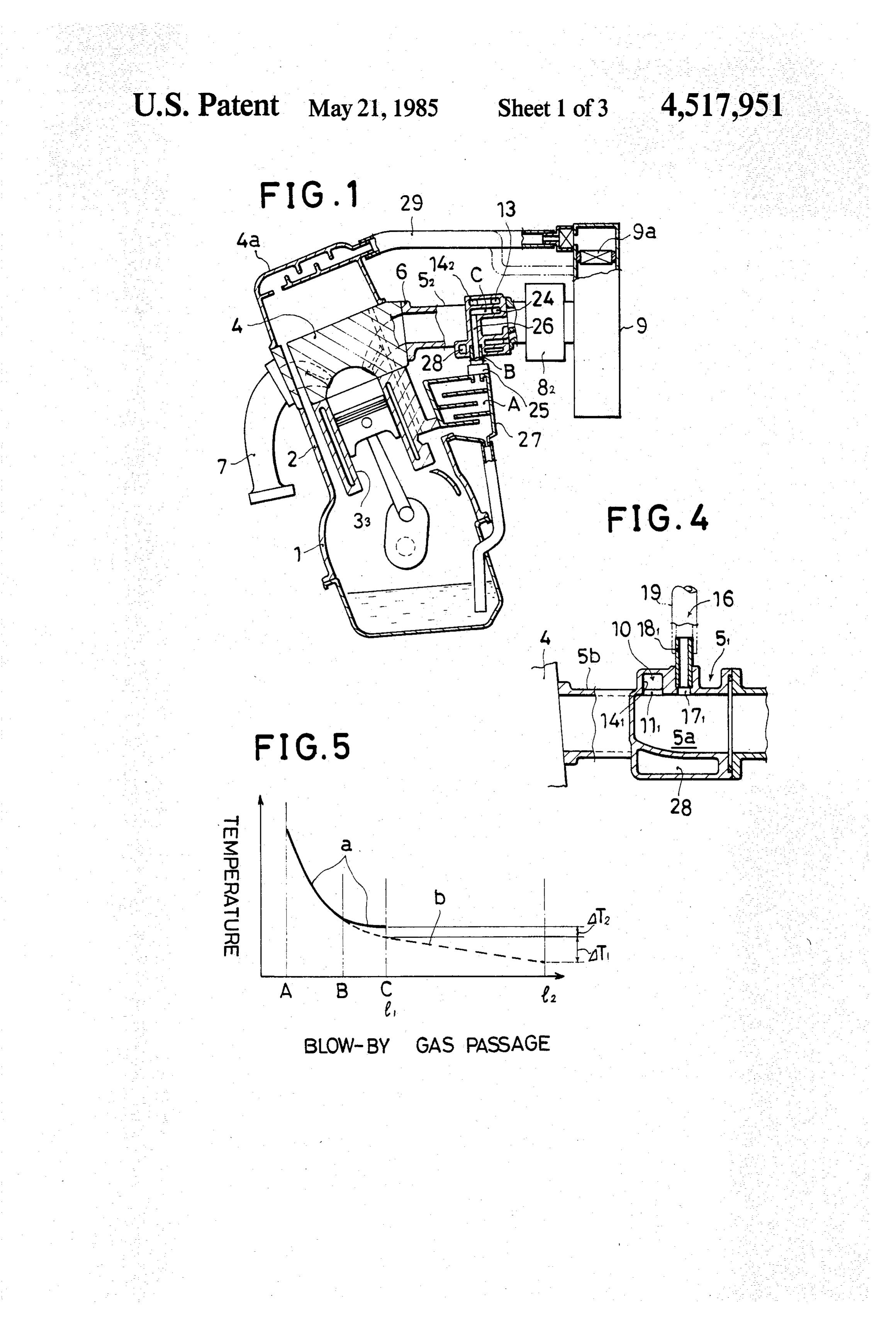
provided therein with first to fourth cylinders 31, 32, 33, 34 arranged in order from the left to the right as shown in FIG. 2. The cylinder head 4 which is an upper part
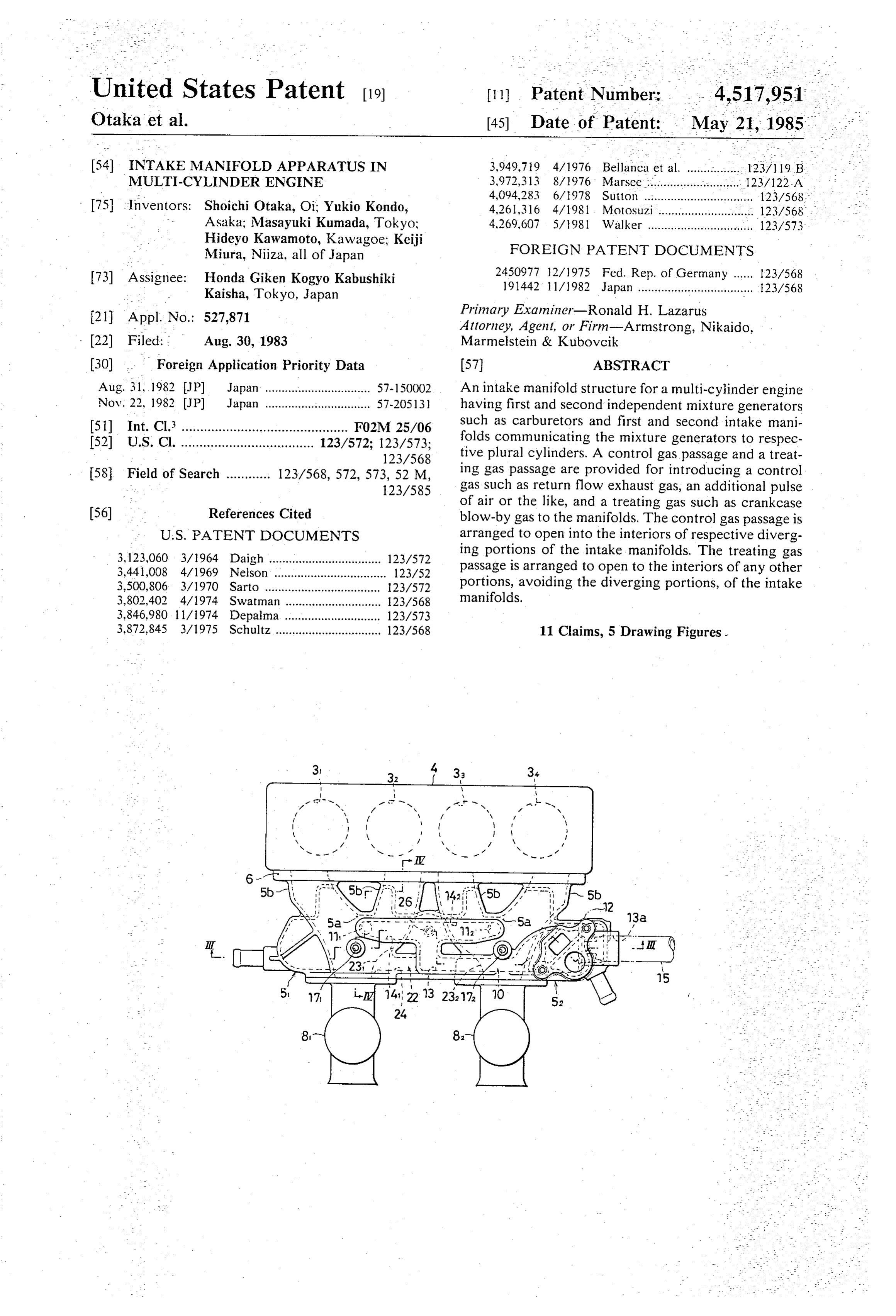
BACKGROUND OF THE INVENTION 5 thereof is provided on one side surface thereof with a This invention relates to an intake system of a multi pair of right and left first and second intake manifolds cylinder engine, and is more particularly directed to an 51, 52 fixed thereto by means of bolts (not illustrated) intake manifold apparatus having first and second inde through a single common attaching flange 6 intercon pendent mixture gas generating means and first and necting those manifolds 51, 52. As shown in FIG. 1, second intake manifolds for communicating between 10 each cylinder head is provided on another side surface these mixture gas generating means and respective plu thereof with an exhaust manifold 7 jointed thereto. ral cylinders of an engine body. Each of the intake manifolds 51, 52 is provided with a An apparatus has been known wherein a control gas pair of distribution pipes 5b, 5t, bifurcated from an inter for the mixture such as return flow exhaust gas, a pulse mediate diverging portion 5a thereof. The two distribu of air or the like and a treating gas such as a blow-by gas 5 tion pipes 5b, 5b of the first intake manifold 51 are con or the like are introduced into respective intake mani nected to the first and second cylinders 31, 32. The two folds through a control gas passage and a treating gas passage, respectively. It is desirable for this type of distribution pipes 5b, 5b of the second intake manifold 52 apparatus to uniformly distribute the control gas for 20 First and secondto carburetors are connected the third and fourth cylinders 33, 34.
81, 82 constituting the first controlling the mixture to the respective cylinders, and and second mixture gas generating means independent to easily provide the two gas passages on the respective one from another are connected to inlet openings of the intake manifolds without being interrupted with each respective intake manifolds 51, 52. As shown in FIG. 1, other.
an air cleaner 9 is connected to upstream side portions
OBJECT AND SUMMARY OF THE INVENTION 25 of the two carburetors 8, 82.
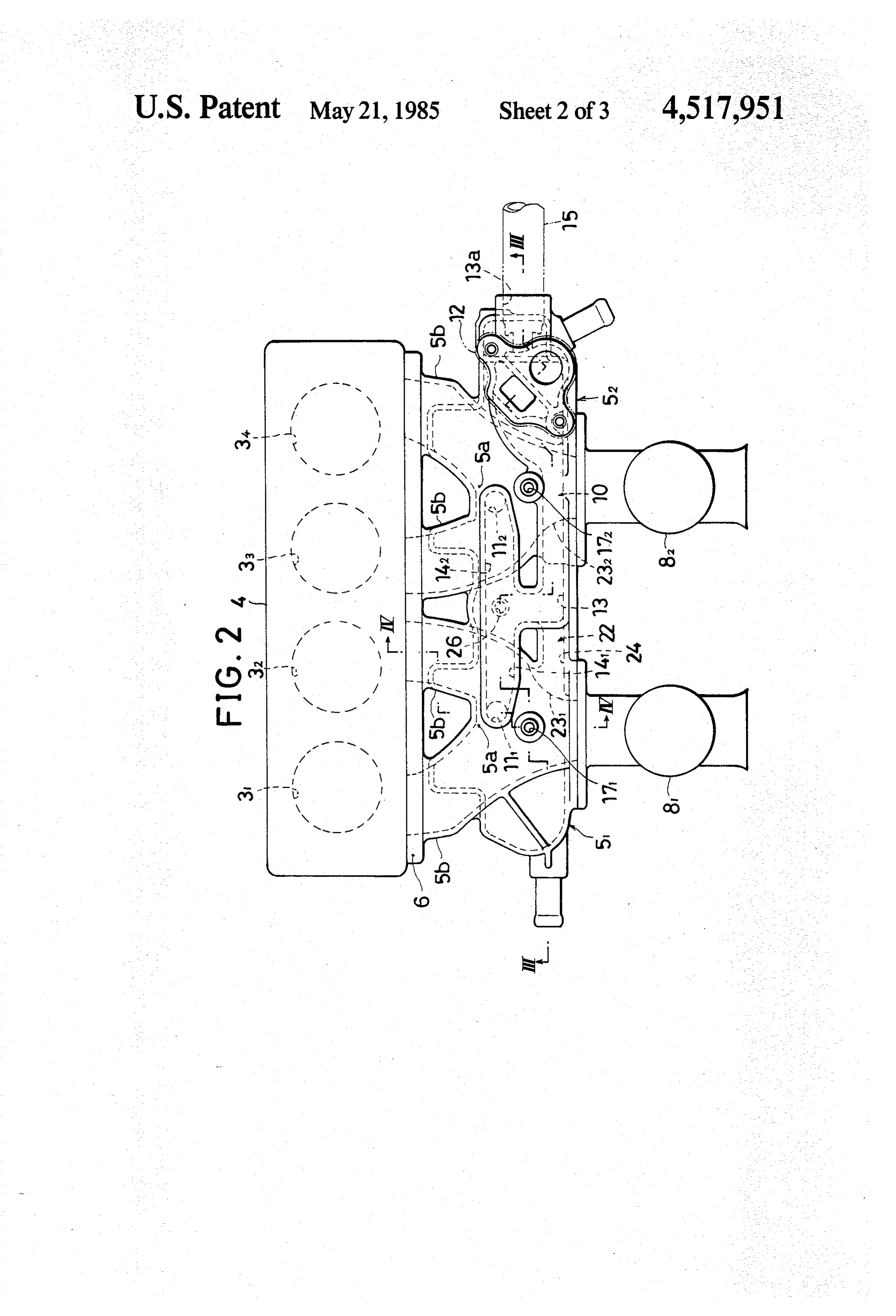
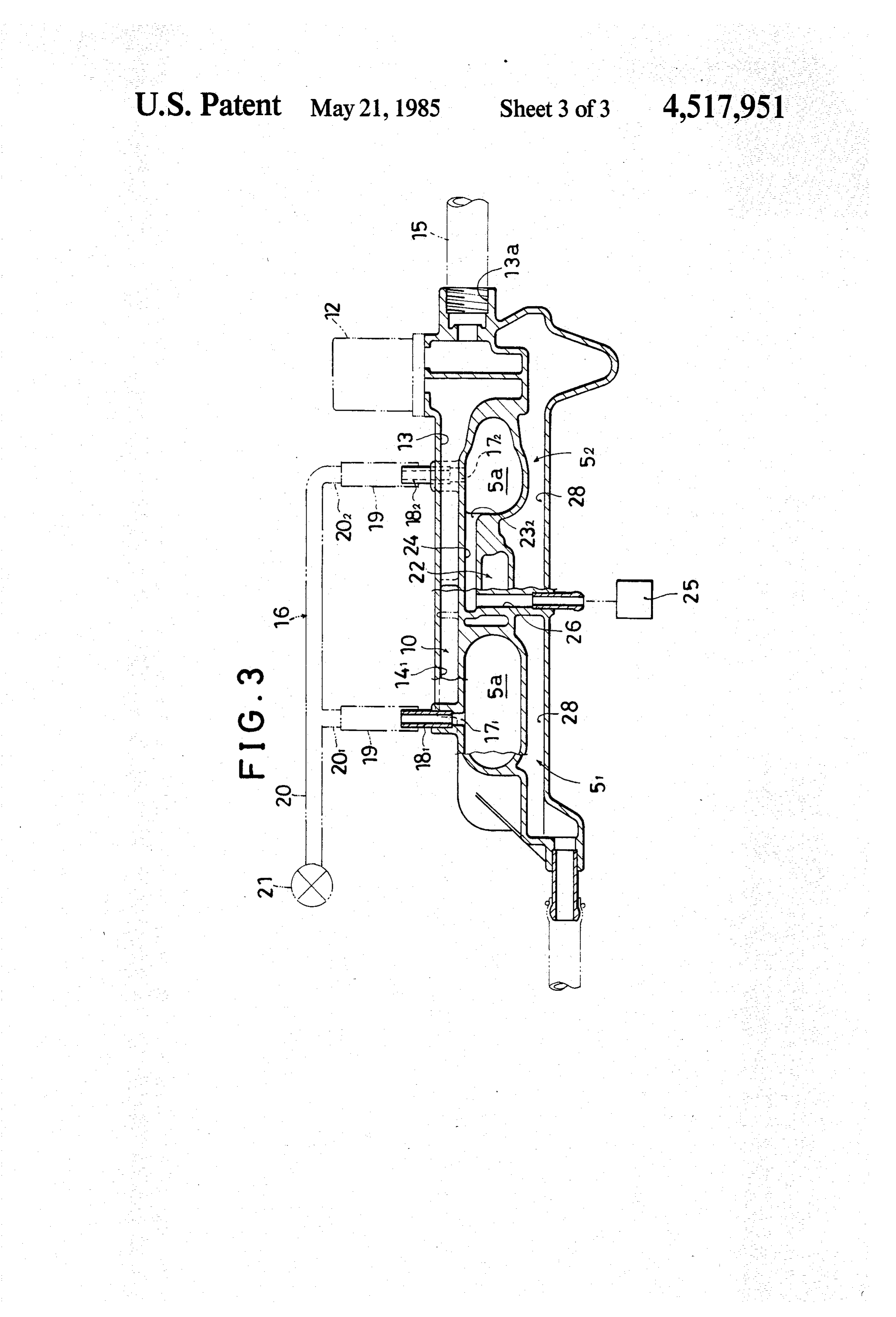
The present invention has as its object to provide an As shown in FIGS. 2 to 4, a return flow exhaust gas intake manifold apparatus which uniformly distributes passage 10 constituting a first control gas passage is the control gas for controlling the mixture to all of the provided to open to the upper portions of the interiors cylinders and which is structured in a simple way. of the diverging portions 5a, 5a of the two intake mani The invention resides in an apparatus having first and 30 folds 51, 52. Open portions thereof are denoted by refer second intake manifolds for communicating between ence numerals 111, 112. In the illustrated example, the these mixtures gas generating means and respective return flow exhaust gas passage 10 comprises a main plural cylinders of an engine body. The intake mani passage 13 having a flow rate control valve 12 inter folds are arranged such that a control gas for control posed therein, and first and second diverged passages ling the mixture gas such as a return flow exhaust gas, a 35 141, 142 diverged from a downstream side of the flowing pulse of air or the like may be introduced thereinto rate control valve 12 and open to the foregoing diverg through a control gas passage and a treating gas such as ing portions 5a, 5a. The first and second diverged pas a blow-by gas or the like may be introduced thereinto sage 141, 142 are formed to be equal in length one to through a treating gas passage. The invention is charac another. A portion of the return flow exhaust gas pas terized in that the control gas passage is arranged to be 40 sage 10 that extends from near the flowing rate control open to the interiors of respective diverging portions of valve 12 to the downstream end portions of the first and the intake manifolds, and the treating gas passage is arranged to be open to the interiors of respective other second diverged passages 141, 142, that is, to the open portions, avoiding the diverging portions, of the intake with the 111, portions two 112 is formed into an integral construction intake manifolds 51, 52 by forming the
same integral with the intake manifolds 51, 52 upon the
BRIEF DESCRIPTION OF THE DRAWINGS casting thereof. The second intake manifold 52 is pro The above and other objects and the attendant advan vided at its outer end surface with an inlet opening 13a tages of the present invention will become readily ap of the main passage 13. A conduit pipe 15 connected to a return flow exhaust gas discharging opening (not parent by reference to the following detailed descrip 50 illustrated) tion when considered in conjunction with the accompa connected tomade in the foregoing exhaust manifold 7 is the inlet opening 13.a.
nying drawings wherein:
FIG. 1 is a sectional side view of one embodiment of Thus, the exhaust gas taken out from the return flow this invention; exhaust gas discharging opening is introduced into the FIG. 2 is a top plan view of an important portion 55 main passage 13 through the conduit pipe 15. In this thereof; example, the same is controlled by the flow rate control FIGS. 3 and 4 are sectional views taken along the line valve 12 so that it has a flow rate corresponding to a III-III and IV-IV in FIG. 2; and particular engine operation condition. Thereafter the FIG. 5 is a diagram showing temperature lowering return flow exhaust gas is uniformly distributed into the characteristics of a blow-by gas. 60 first and second diverged passages 141, 142 of the same length for being supplied to the respective diverging
DETAILED DESCRIPTION OF A PREFERRED portions 5a, 5 of the first and second intake manifolds EMBODIMENT 51, 52. Accordingly, the return flow exhaust gas sup One embodying example of this invention will be plied to each diverging portion 5a is uniformly distrib explained with reference to the accompanying draw 65 uted into the corresponding two distribution pipes 5b, ings: 5b. Thus, the return flow exhaust gas is supplied to the In the illustrated example wherein this invention is first to fourth cylinders 31-34 uniformly together with applied to a four-cylinder engine, a cylinder block 2 the mixture gas, and can serve to decrease the genera
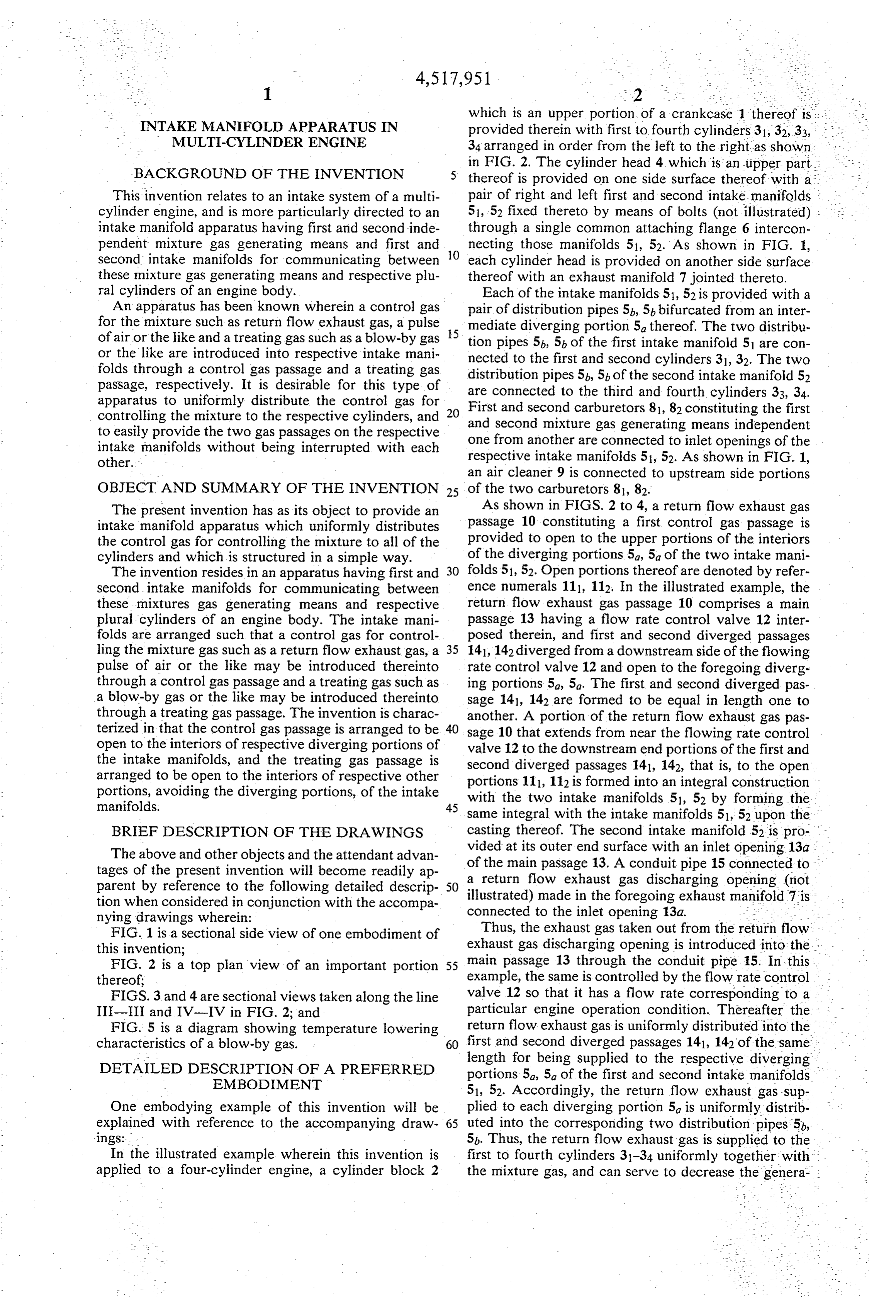
Page 6
tion of NO at the time of combustion of the mixture Additionally, the two intake manifolds 51, 52 are pro gas. vided at a bottom wall thereof with respective hot Additionally, an impulse air passage 16 constituting a water riser portions 28 for heating the mixture gas flow second control gas passage is arranged to be open to ing through the intake manifolds 51, 52 by flowing there upper portions of the interiors of the respective diverg through cooling water heated by the engine. The treat ing portions 5a, 5a of the first and second intake mani ing gas passage 22 is arranged to be inserted, at the folds 51, 52. The open portions thereof are indicated by introducing passage 26 thereof, through the hot water reference numerals 171, 172. The impulse air passage 16 riser portions 28 so that freezing of moisture contained comprises first and second introducing pipes 181, 182 in the blow-by gas in the treating gas passage 22 or in jointed by casting to upper walls of the diverging por 10 the PCV valve 25 may be effectively prevented by a tions 5, 5 and a metallic diverged pipe 20 having heat transmission from the hot water riser portions 28. branch portions 201, 202 connected through respective Otherwise, freezing in the treating gas passage 22 or flexible connecting pipes 19, 19 of rubber or the like to in the PCV valve 25 would result in an increase in these introducing pipes 181, 182. The inlet opening of 15 internal pressure of the crankcase 1. The blow-by gas the pipe 20 is provided with an impulse air valve 21. would then flow backwards to the air cleaner 9 through At the time of beginning of an engine deceleration an external air introducing passage 29 connected to the operation wherein the mixture gas become temporarily cylinder head cover 4a as shown in FIG. 1. The filter element 9a of the air cleaner 9 would be contaminated rich, the impulse air valve 21 detects this rich condition with oil mist or the like contained in the blow-by gas. to operate, and a predetermined amount of impulse air is 20 uniformly distributed through the branch pipe 20 to the Also, if the passage 29 is connected to a clean side of air first and second introducing pipes 18, 182, and is sup cleaner 9 as shown by dotted lines in FIG. 1, the respec tive carburetors 81, 82 connected thereto would be con plied to the respective diverging portions 5a, 5a of the taminated.
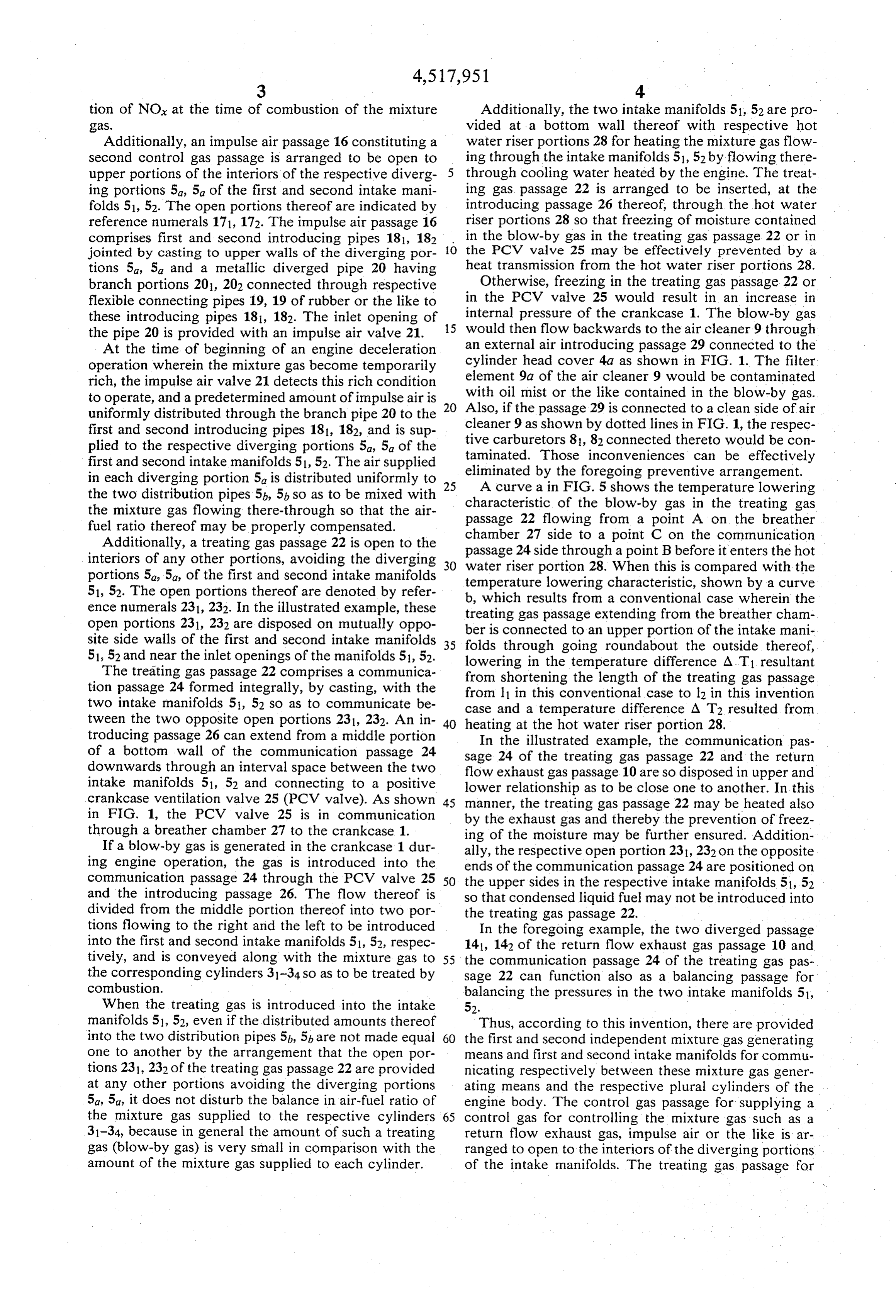
first and second intake manifolds 51, 52. The air supplied eliminated by Those inconveniences can be effectively in each diverging portion 5a is distributed uniformly to 25 A curve a inthe foregoing preventive arrangement. the two distribution pipes 5b, 5b so as to be mixed with characteristic ofFIG. the 5 shows the temperature lowering blow-by gas in the treating gas the mixture gas flowing there-through so that the air passage 22 flowing from a point A on the breather fuel ratio thereof may be properly compensated. chamber 27 side to a point C on the communication Additionally, a treating gas passage 22 is open to the interiors of any other portions, avoiding the diverging 30 passage 24 side through a point B before it enters the hot portions 5a, 5a, of the first and second intake manifolds water riser portion 28. When this is compared with the temperature lowering characteristic, shown by a curve 51, 52. The open portions thereof are denoted by refer b, which results from a conventional case wherein the ence numerals 231, 232. In the illustrated example, these treating gas passage extending from the breather cham open portions 231, 232 are disposed on mutually oppo ber is connected to an upper portion of the intake mani site side walls of the first and second intake manifolds 35 folds through going roundabout the outside thereof, 51, 52 and near the inlet openings of the manifolds 51, 52. lowering in the temperature
The treating gas passage 22 comprises a communica from shortening the length ofdifference the AT1 resultant treating gas passage tion passage 24 formed integrally, by casting, with the from 11 in this conventional case to lz in this invention two intake manifolds 51, 52 so as to communicate be case and a temperature difference A T2 resulted from tween the two opposite open portions 231, 232. An in 40 heating at the hot water riser portion 28. troducing passage 26 can extend from a middle portion In the illustrated example, the communication pas of a bottom wall of the communication passage 24 sage 24 of the treating gas passage 22 and the return downwards through an interval space between the two flow exhaust gas passage 10 are so disposed in upper and intake manifolds 51, 52 and connecting to a positive lower relationship as to be close one to another. In this crankcase ventilation valve 25 (PCV valve). As shown 45 manner, the treating gas passage 22 may be heated also in FIG. 1, the PCV valve 25 is in communication by the exhaust gas and thereby the prevention of freez through a breather chamber 27 to the crankcase 1. ing of the moisture may be further ensured. Addition If a blow-by gas is generated in the crankcase 1 dur ally, the respective open portion 23, 232 on the opposite ing engine operation, the gas is introduced into the ends of the communication passage 24 are positioned on communication passage 24 through the PCV valve 25 50 the upper sides in the respective intake manifolds 51, 52 and the introducing passage 26. The flow thereof is so that condensed liquid fuel may not be introduced into divided from the middle portion thereof into two por the treating gas passage 22.
tions flowing to the right and the left to be introduced In the foregoing example, the two diverged passage into the first and second intake manifolds 51, 52, respec 141, 142 of the return flow exhaust gas passage 10 and tively, and is conveyed along with the mixture gas to 55 the communication passage 24 of the treating gas pas the corresponding cylinders 31-34 so as to be treated by sage 22 can function also as a balancing passage for combustion. balancing the pressures in the two intake manifolds 51, When the treating gas is introduced into the intake 52.
manifolds 51, 52, even if the distributed amounts thereof Thus, according to this invention, there are provided into the two distribution pipes 5b, 5t, are not made equal 60 the first and second independent mixture gas generating one to another by the arrangement that the open por means and first and second intake manifolds for commu tions 231, 232 of the treating gas passage 22 are provided nicating respectively between these mixture gas gener at any other portions avoiding the diverging portions ating means and the respective plural cylinders of the 5a, 5a, it does not disturb the balance in air-fuel ratio of engine body. The control gas passage for supplying a the mixture gas supplied to the respective cylinders 65 control gas for controlling the mixture gas such as a 31-34, because in general the amount of such a treating return flow exhaust gas, impulse air or the like is ar gas (blow-by gas) is very small in comparison with the ranged to open to the interiors of the diverging portions amount of the mixture gas supplied to each cylinder. of the intake manifolds. The treating gas passage for
Page 7
supplying a treating gas such as a blow-by gas or the from the crankcase to both said first and second like is arranged to open to the interiors of any other intake manifolds at a location between said first and portions than the diverging portions, of the intake mani second areas thereof downstream from said first folds. Thus, the positioning of the respective open por aea.S.
tions of the control gas passage and the treating gas 5 2. The apparatus of claim 1, wherein the control gas passage to each of the intake manifolds near to another passage comprises a main passage, a flow rate control can be avoided. At the same time the two passages can valve in the main passage for controlling the flow rate be easily disposed without interfering with one another. of the control gas interposed therein, and diverged Additionally, the control gas which affects the combus passages diverged from the main passage downstream tion condition of the mixture gas can be distributed 10 of the flow rate control valve and connected to the uniformly to the plural distribution pipes as a result of respective second areas, each diverged passage being being supplied to the respective diverging portions of substantially equal in length to the other. the intake manifolds. The air-fuel ratio and other prop 3. The apparatus of claim 2, wherein at least a portion erties of the mixture gas supplied to each cylinder of the of the control gas passage which extends from the posi engine can be properly controlled and there can be 15 tion of the flow rate control valve to the downstream always obtained a good combustion condition. On the ends of the diverged passages is constructed integral other hand, the treating gas is supplied to the respective with the intake manifolds.
intake manifolds through any other positions than the 4. The apparatus of claim 1, wherein the control gas diverging portions, so that the same tends to be supplied passage is made of a pipe material. unequally to certain cylinders. However, owing to the 20 5. The apparatus of claim 1 wherein the vapor pas fact that the amount thereof is generally very small, it sage includes a communication passage open at its op does not give any bad influence on the proper combus posite end portions to the interiors of the intake mani tion condition of the mixture at any of the cylinders. folds.
It is readily apparent that the above-described intake 6. The apparatus of claim 1 wherein the manifolds manifold apparatus meets all of the objects mentioned 25 include a hot water riser portion provided on lower above and also has the advantage of wide commercial surfaces thereof and said vapor passage is inserted utility. It should be understood that the specific form of therethrough.
the invention hereinabove described is intended to be 7. The apparatus of claim 6, wherein said vapor pas representative only, as certain modifications within the sage has a communication passage open at its opposite scope of these teachings will be apparent to those skilled 30 end portions to the interiors of the two intake manifolds, in the art. and an introducing passage extending downwards from Accordingly, reference should be made to the follow the communication passage through an interval space ing claims in determining the full scope of the invention. formed between the two intake manifolds and is in What is claimed: serted through hot water riser portion. 1. In a plural cylinder internal combustion engine 35 8. The apparatus of claim 5, wherein the communica which includes a crankcase, a first and a second inde tion passage is provided near the control gas passage for pendent air-fuel gas generating means, first and second a return flow exhaust gas.
intake manifolds each including a first area to which a 9. The apparatus of claim 5, wherein both the end respective air-fuel gas generating means is mounted and portions of the communication passages are arranged to a second area where divergent flow paths are provided, 40 open to upper portions of the interiors of the respective said divergent paths being downstream from the first intake manifolds.
area in the flow path of the air-fuel gas toward the 10. The apparatus of claim 7, wherein the communi engine, wherein the improvement comprises: cation passage is provided near the control gas passage a source of control gas consisting of either engine for a return flow exhaust gas.
exhaust or an auxiliary air supply at least one con 45 11. The apparatus of claim 9, wherein both the end trol gas passage for feeding said control gas from at portions of the communication passages are arranged to least one source of said control gas to both said first open to upper portions of the interiors of the respective and second intake manifolds at said second areas intake manifolds.
thereof, and a crankcase vapor passage connected ck sk sk k k
Provenance
- Collection
- Cited prior art
- Original PDF
- patentimages.storage.googleapis.com →
- Filed
- 1983-08-30
- Pages
- 7
- Method
- pdftotext (the PDF's own text layer) + pdftoppm 300dpi page scans
- Source
- Google Patents bibliographic record
- Granted
- 1985-05-21
- Inventors
- Shoichi Otaka; Yukio Kondo; Masayuki Kumada; Hideyo Kawamoto; Keiji Miura; Honda Motor Co Ltd
- Transcribed from
- patentimages.storage.googleapis.com →