patent · US20130334899A1
Electrical generation systems and methods
19 December 2013
Page 1 — bibliographic record
(19) United States (12) Patent Application Publication (10) Pub. No.: US 2013/0334899 A1
Motisse (43) Pub. Date: Dec. 19, 2013 (54) ELECTRICAL GENERATION SYSTEMS AND Publication Classification
METHODS
(71) Applicant: Benjamin Francis John Hallgren, West HO2K 44/00 (2006.01)
CPC ...................................... H02K 44/00 (2013.01) (72) Inventor: Susan Motisse, Burleigh Heads (AU) USPC ............................................................ 31 O/11
(21) Appl. No.: 13/971,888 An apparatus and method for generating electricity are dis closed. A ferroliquid having magnetic dipoles is confined in a (22) Filed: Aug. 21, 2013 conduit which is endless and can have a spiral configuration. 9 The conduit has an electric coil wrapped around it. A tem perature difference and a first magnetic field are applied to the
Related U.S. Application Data liquid, thereby both moving and aligning the dipoles of the (63) Continuation-in-part of application No. 13/244,484. ferroliquid. The aligned dipoles create a second magnetic filed on Sep. 25, 2011. field which interacts with the coil to generate an emf therein.
Page 2
Drawing sheet — no readable text.
Page 3
Drawing sheet — no readable text.
Page 4
Drawing sheet — no readable text.
Page 5
Drawing sheet — no readable text.
Page 6
Drawing sheet — no readable text.
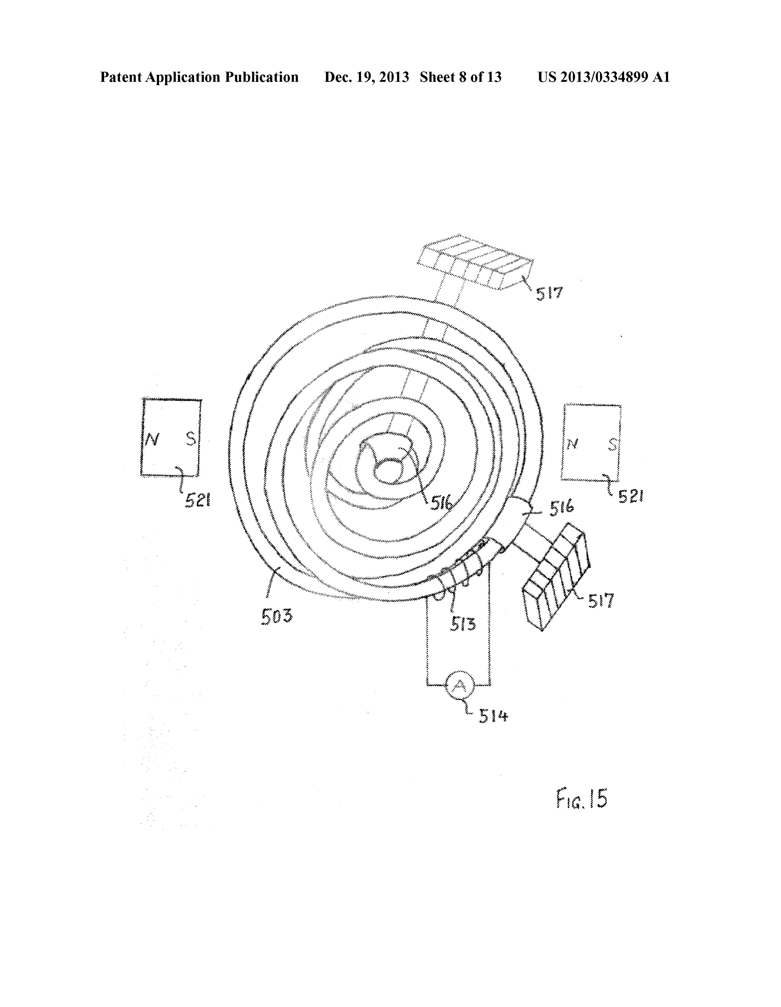
Page 7
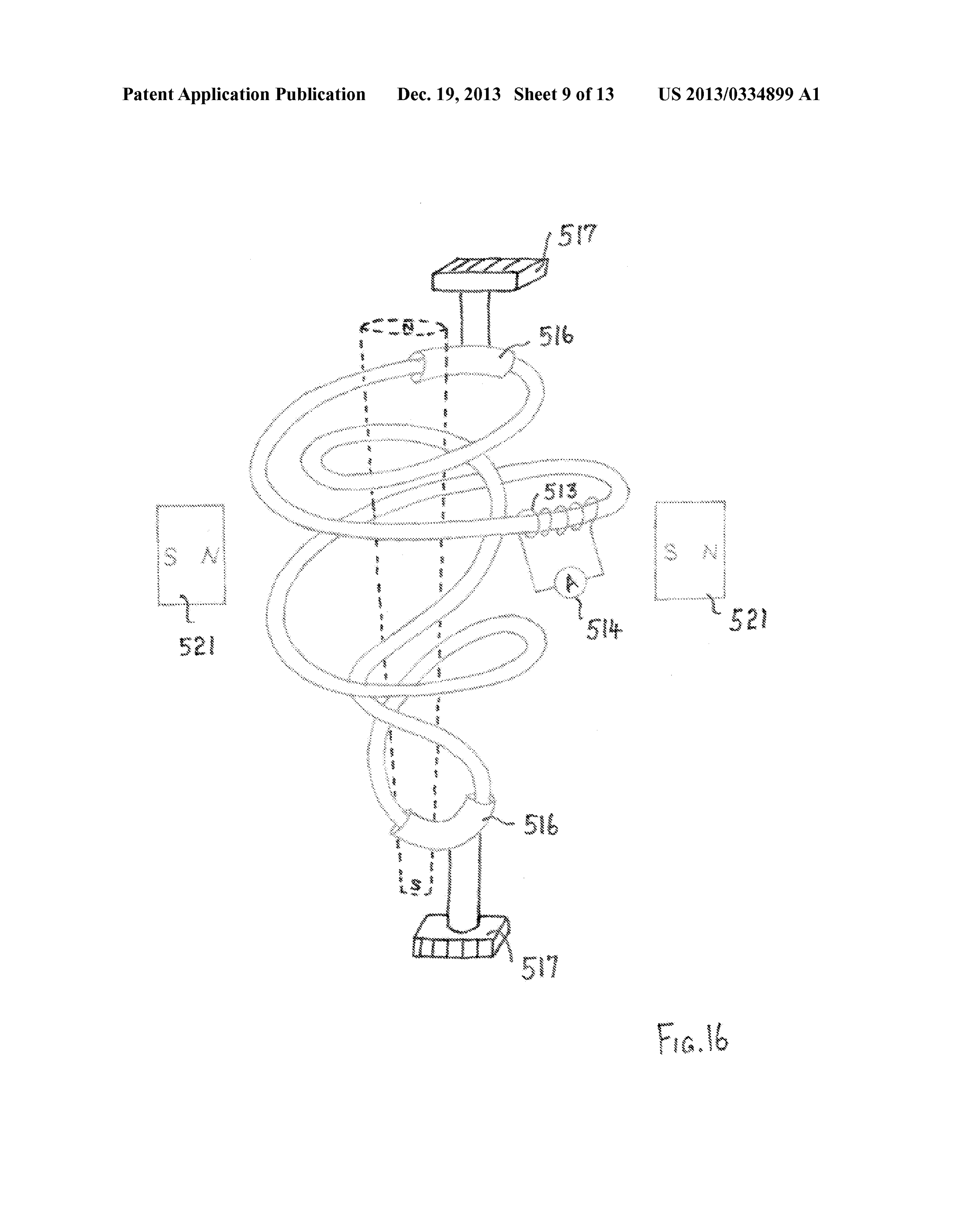
Drawing sheet — no readable text.
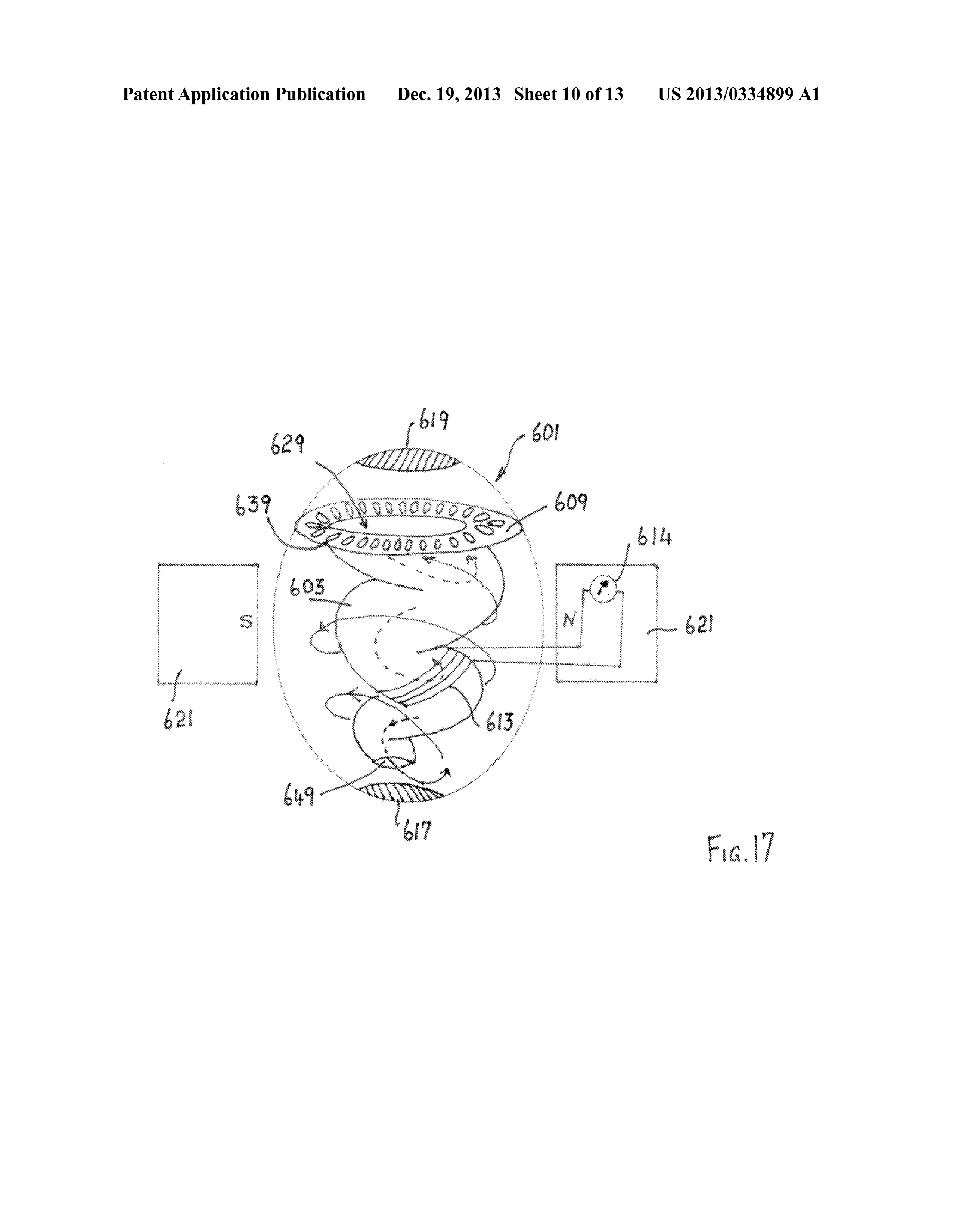
Page 8
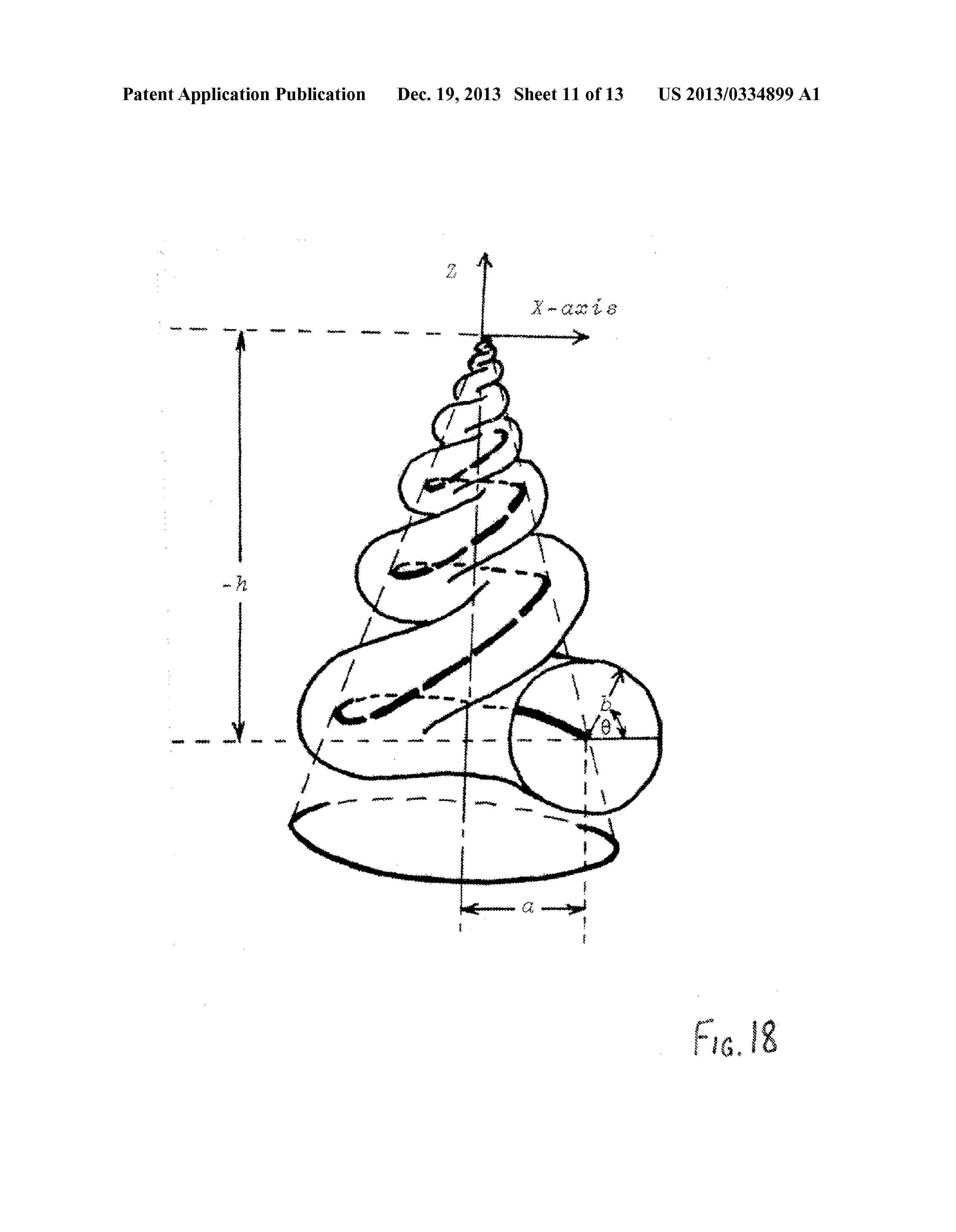
Drawing sheet — no readable text.
Page 9
Drawing sheet — no readable text.
Page 10
Drawing sheet — no readable text.
Page 11
Drawing sheet — no readable text.
Page 12
Drawing sheet — no readable text.
Page 13
Drawing sheet — no readable text.
Page 14
Drawing sheet — no readable text.
Page 15
US 2013/0334899 A1 Dec. 19, 2013
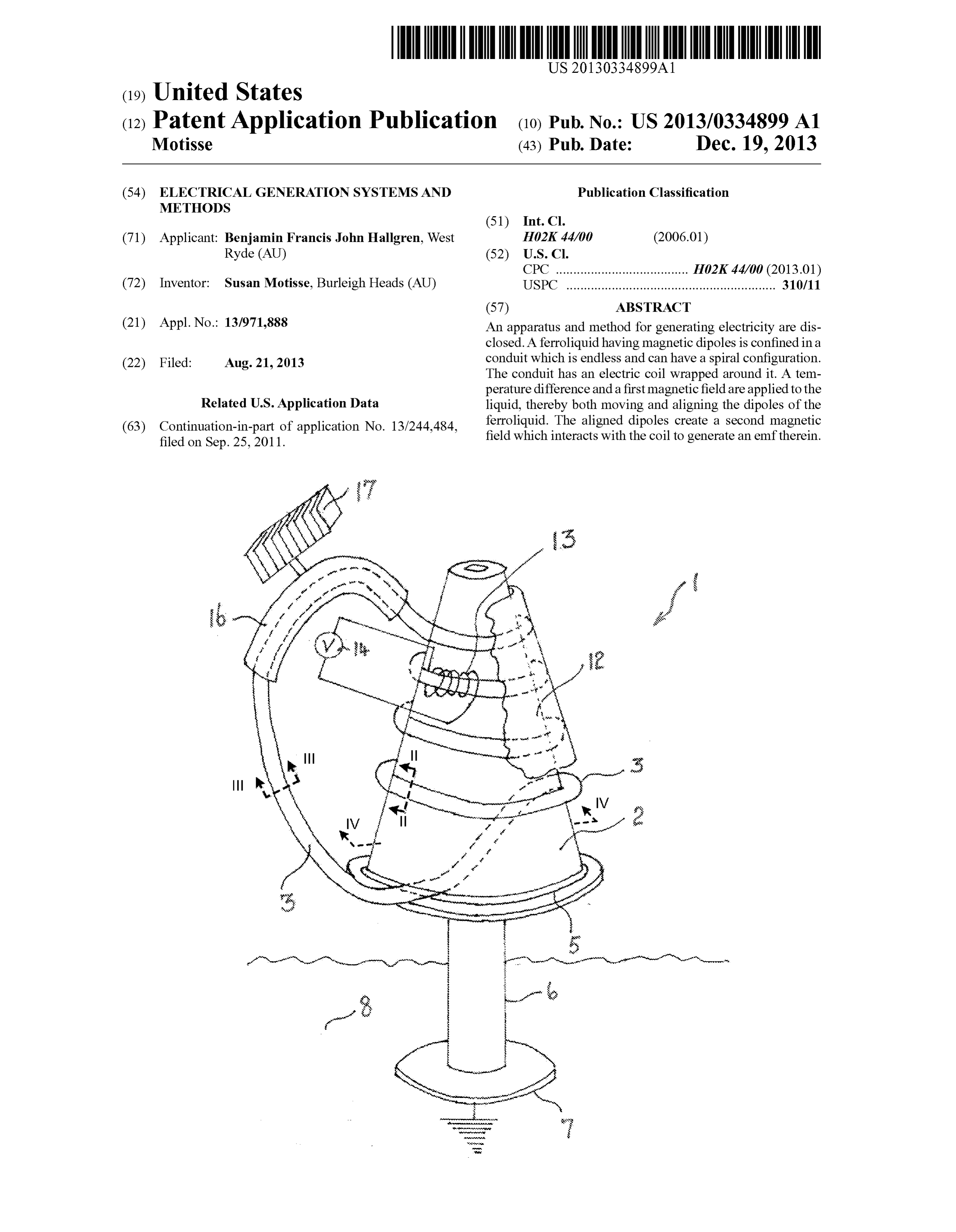
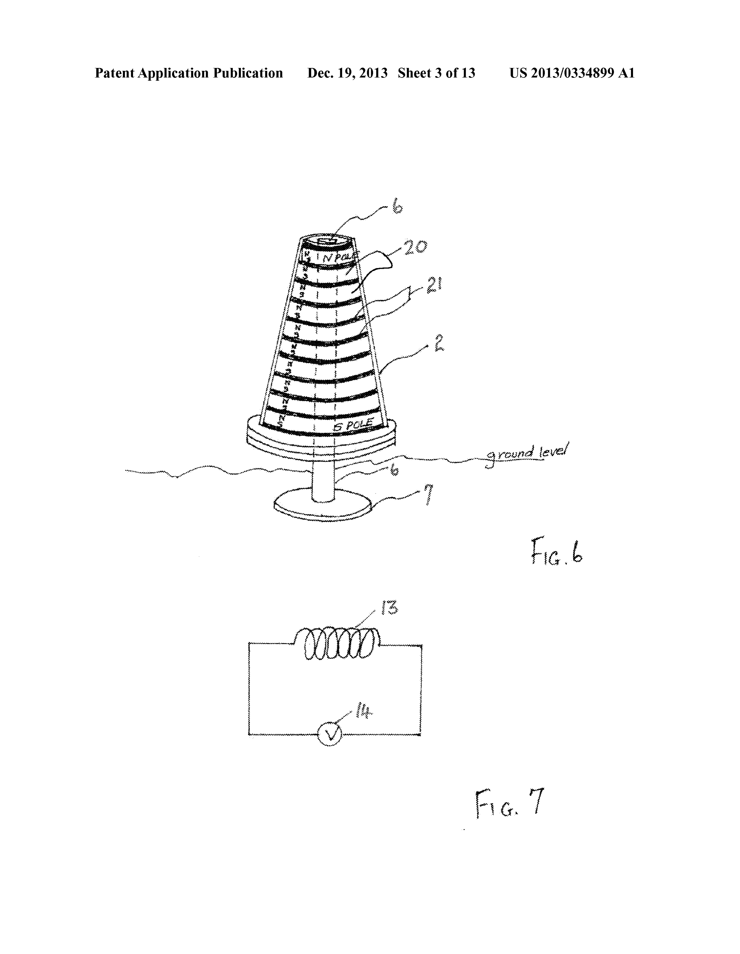
ELECTRICAL GENERATION SYSTEMIS AND 0012 FIG. 6 is a perspective view of the generator of FIG. METHODS 1 showing an arrangement of permanent magnets in accor dance with an embodiment of the present invention;
BACKGROUND OF THE INVENTION 0013 FIG. 7 is a circuit diagram illustrating the electrical connection of the coil of FIG. 1;
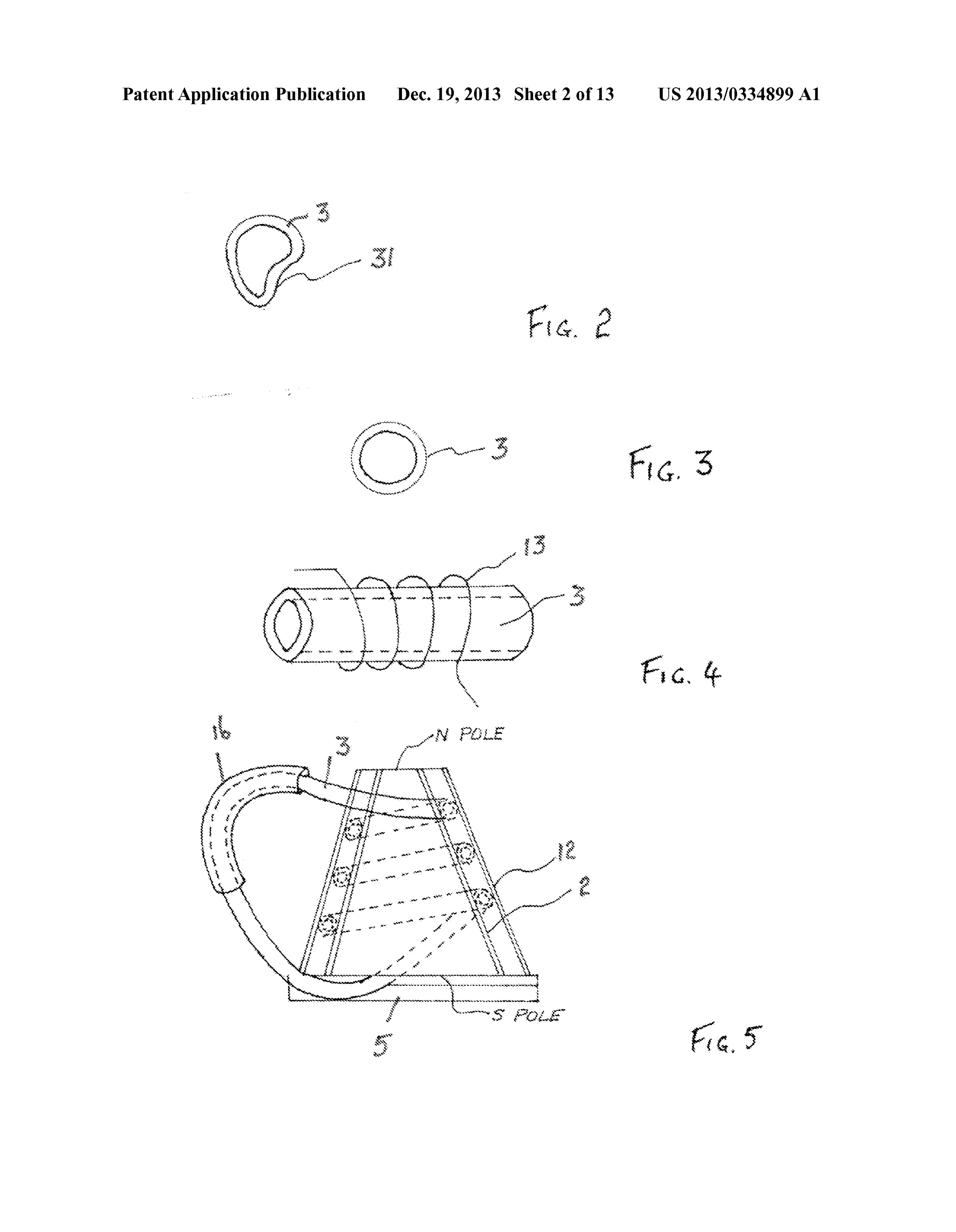
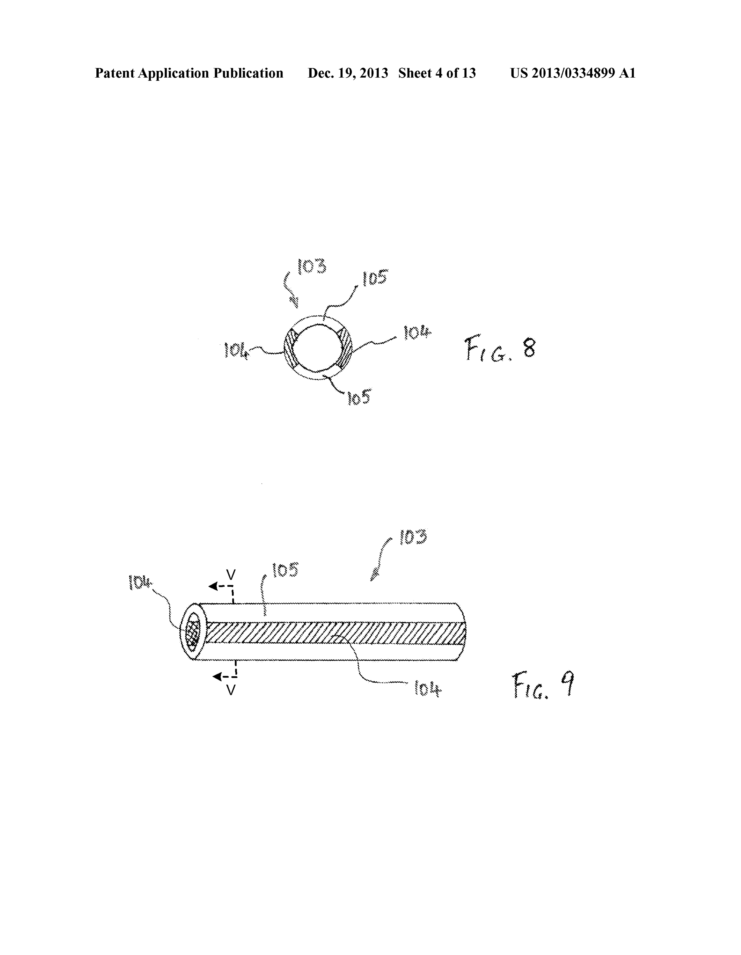
0001. The present invention relates to the generation of 0014 FIG. 8 is a cross-sectional view of the conduit of electricity and, in particular, by the conversion of thermal FIG. 9 taken along the line V-V of FIG. 9 illustrating an energy into electrical energy making use of a liquid which alternative arrangement for a conduit including thermally includes particles having a magnetic dipole. conductive portions in accordance with an embodiment of the 0002. Over the years many proposals have been put for present invention;
ward to provide electric generators of various kinds. The (0015 FIG.9 is a perspective view of the conduit illustrated following patents are representative of this art, namely U.S. in FIG. 8:
Pat. Nos. 4,064,409, 5,632,093, 6,489,694, 6,504,271, 6,628, 0016 FIG. 10 is a perspective view of a generator inaccor 017, 6,982,501, 7,061,129, 7,095,143, 7,105,935 and 7,745, dance with another embodiment of the present invention;
0017 FIG. 11 is a perspective view illustrating another 0003. There is a need for improved methods and appara alternative arrangement for a conduit in accordance with tuses for generating electricity that overcome deficiencies of another embodiment of the present invention; the prior art. 0018 FIG. 12 is a perspective view of a generator inaccor
SUMMARY OF THE INVENTION
dance with another embodiment of the present invention;
0019 FIG. 13 is a cross-sectional view of the generator of 0004. In accordance with a first aspect of the present FIG. 12 taken along the line VI-VI of FIG. 12; invention there is disclosed a method of generating electricity, 0020 FIG. 14 is a cross-sectional view similar to FIG. 13 said method comprising the steps of confining a liquid but of a generator in accordance with another embodiment of including particles having a magnetic dipole to a conduit the present invention;
formed into an endless loop, winding a coil around at least a 0021 FIG. 15 is a plan view of a generator in accordance portion of said conduit, exposing said conduit to a tempera with another embodiment of the present invention; ture difference to establish a convective flow in said liquid 0022 FIG. 16 is a perspective view of the generator of through said conduit, and exposing said liquid to a first mag FIG. 15:
netic field to align said particles whilst within said magnetic 0023 FIG. 17 is a perspective view of a generator incor field, wherein a second magnetic field produced by said porating a gnomic spiral in accordance with another embodi aligned dipoles moves relative to said coil to thereby generate ment of the present invention;
an electromotive force (hereafter “emf) therein. 0024 FIG. 18 is drawing of a gnomic spiral of the type 0005. In accordance with a second aspect of the present utilized in the generator of FIG. 17: invention there is disclosed an apparatus for generating elec 0025 FIG. 19 illustrates a mathematical formula for a tricity, said apparatus comprising a conduit formed into an gnomic Surface; and endless loop and confining a liquid including particles having 0026 FIG.20 is a perspective view of a generator inaccor a magnetic dipole, a coil wound around at least a portion of dance with another embodiment of the present invention. said conduit, heat transfer means connected with said conduit to establish a temperature difference in said conduit which DETAILED DESCRIPTION OF THE PREFERRED establishes a convective flow in said liquid through said con EMBODIMENTS duit, and a pair of magnetic poles between which extends a 0027. The ensuing detailed description provides preferred first magnetic field to which said liquid is exposed to align exemplary embodiments only, and is not intended to limit the said particles whilst within said magnetic field, whereby a Scope, applicability, or configuration of the invention. Rather, second magnetic field produced by said aligned dipoles the ensuing detailed description of the preferred exemplary moves relative to said coil to thereby generate an emf therein. embodiments will provide those skilled in the art with an BRIEF DESCRIPTION OF THE DRAWINGS enabling description for implementing the preferred exem plary embodiments of the invention. It being understood that 0006. The present invention will hereinafter be described various changes may be made in the function and arrange in conjunction with the appended drawing figures wherein ment of elements without departing from the spirit and scope like numerals denote like elements. of the invention, as set forth in the appended claims. In addi 0007 FIG. 1 is a perspective view of a generator apparatus tion, reference numerals that are introduced in the specifica in accordance with an embodiment of the present invention; tion in association with a drawing figure may be repeated in one or more Subsequent figures without additional descrip 0008 FIG. 2 is a cross-sectional view taken along the line tion in the specification in order to provide context for other II-II of FIG. 1 and showing a first form of a conduit; features.
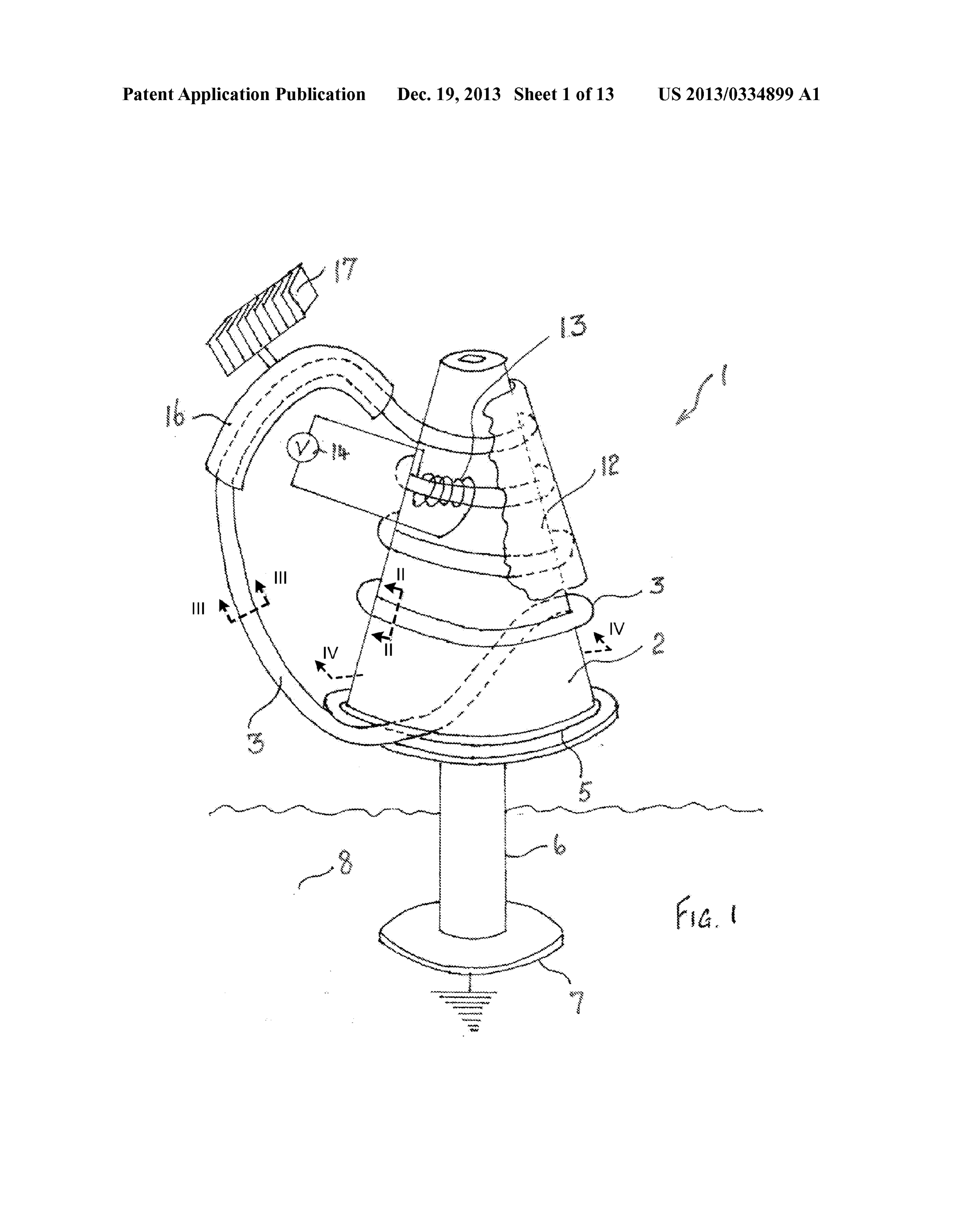
0009 FIG. 3 is a cross-sectional view taken along the line 0028. As seen in FIG. 1, a generator 1 takes the form of a III-III of FIG. 1 and showing a second form of a conduit; cone shaped thermal conductor 2. Wrapped around the cone 0010 FIG. 4 is a perspective view illustrating the winding shaped thermal conductor 2 is a conduit 3 which is non of a coil around a conduit in accordance with an embodiment conducting and which is configured into a conical spiral as of the present invention; illustrated.
0011 FIG. 5 is a cross-sectional view through the upper 0029. The cone shaped thermal conductor 2 is supported portion of the generator of FIG. 1 taken along the line IV-IV by a thermally conductive disc 5 which is supported by a of FIG. 1; thermally conductive stem 6 which terminates in a thermally
Page 16
US 2013/0334899 A1 Dec. 19, 2013
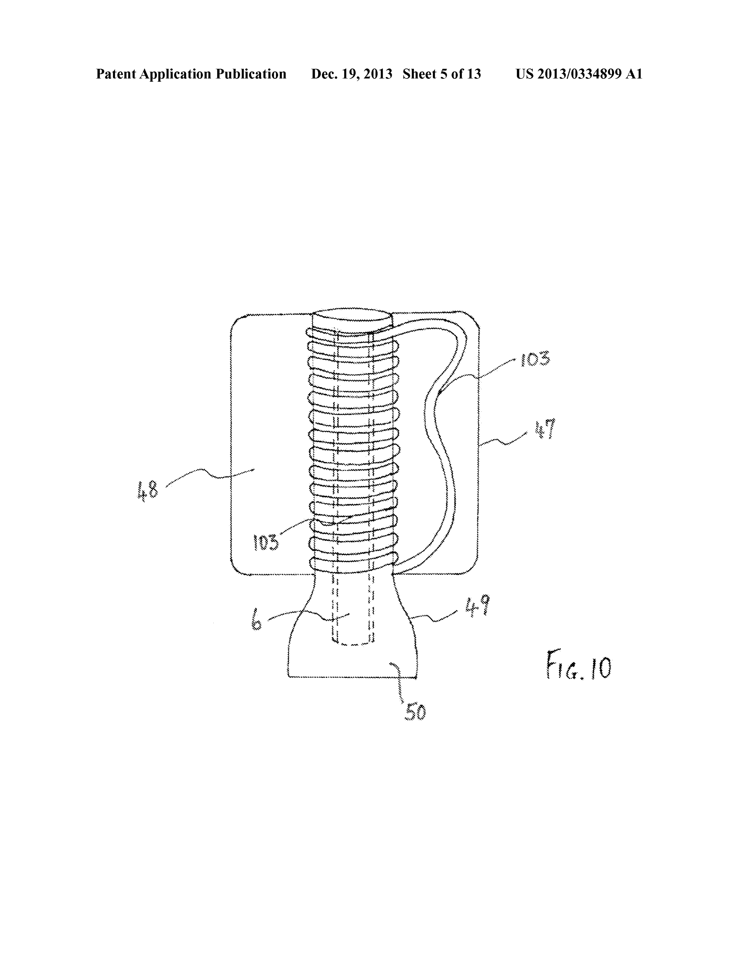
conductive plate 7 that is in thermal communication with conduit 103 lies within the heat exchanger 47. The thermally earth 8 (or a different heat sink). conductive stem 6 is surrounded by a cylindrical housing 49 0030 Located exterior of the conduit 3 is a second cone upon which the conduit 103 is coiled and which contains a shaped thermal conductor 12 which is only shown in frag liquid 50 which is in thermal communication with the ther mentary form in FIG.1. Intermediate the conductors 2, 12 the mally conductive stem 6 and therefore the earth 8 (illustrated conduit 3 has a coil 13 formed from insulated electrical wire in FIG. 1).
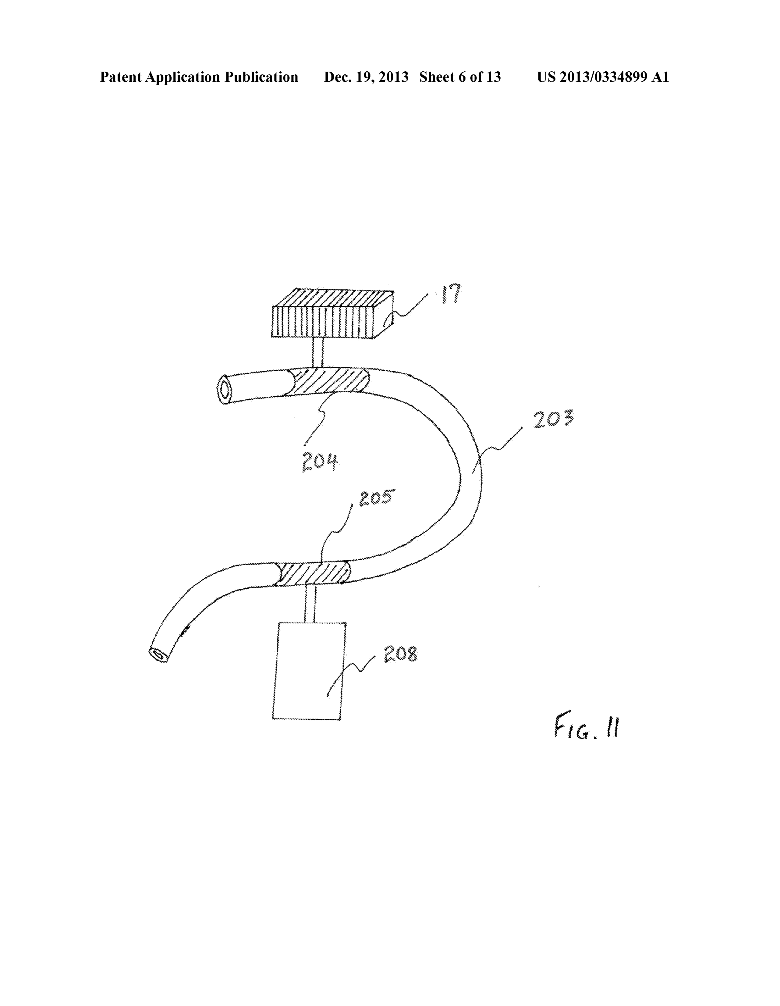
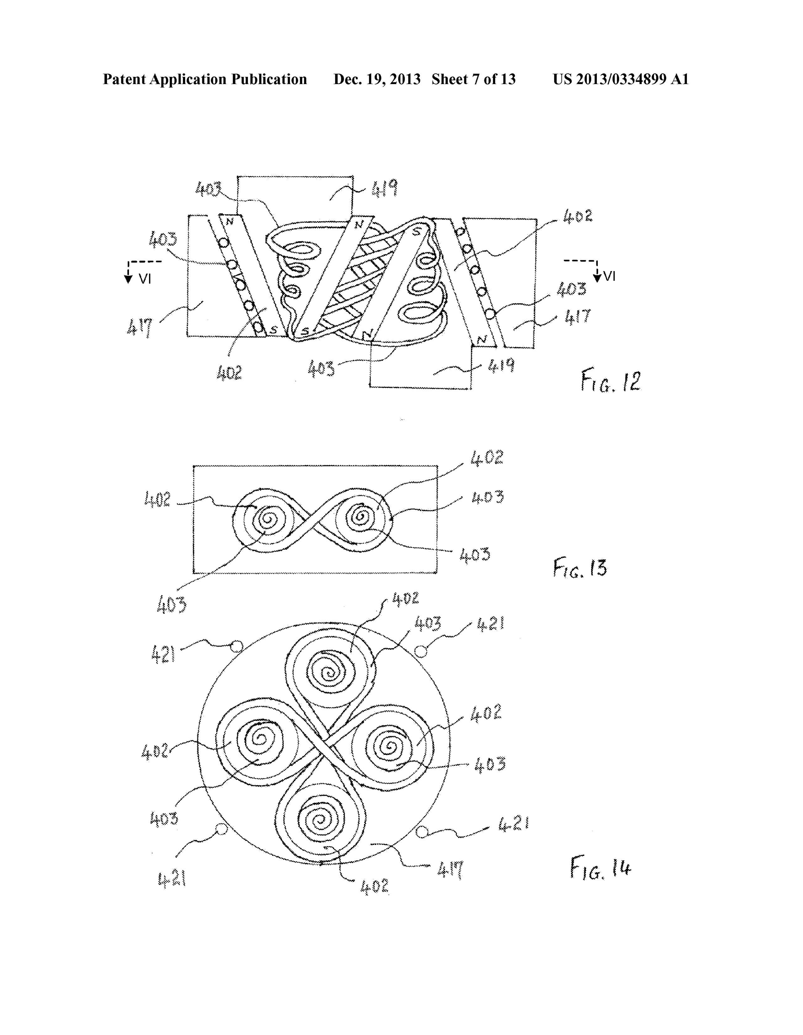
which is wrapped around the conduit 3. The coil 13 can be 0039. In FIG. 11 an alternative heat exchanger arrange spiral, helical, solenoidal or helicoidal. The coil 13 is con ment for a conduit 203 is illustrated. The conduit 203 is not nected to a volt meter 14. thermally conductive but has two thermally conductive por 0031. In addition, the conduit 3 passes through a thermally tions 204, 205 which are respectively connected to the heat conductive sleeve 16 which is thermally connected to a heat exchanger 17 and a heat sink 208 which can include a tank of exchanger 17. The heat exchanger is exposed to Solar radia water, for example, or the earth 8 as illustrated in FIG.1. The tion (or Some other heat Source Such as industrial waste heat, two thermally conductive portions 204, 205 are constructed a geothermal heat source, or the like). so as to have an internal surface which is flush with the 0032. As seen in FIG. 2, the conduit 3 preferably has a internal surface of the conduit 203 so as to thereby ensure a flattened surface 31 which lies against the interior cone smooth flow of the fluid having the magnetic dipoles. shaped thermal conductor 2 thereby increasing the thermal 0040 Turning now to FIGS. 12 and 13, a duplicated transfer without impeding flow of liquid through the conduit arrangement is illustrated with two heat sources 417 and two 3. heat sinks 419. The heat sinks are in thermal communication 0033 Alternatively, as seen in FIGS. 3 and 4, the conduit with two cone shaped thermal conductors 402 each of which 3 can be provided with a circular cross-section which can has a corresponding conduit 403. Each conduit 403 spirals either be constant or varying along its length. through the interior of the cone shaped thermal conductors 0034. As seen in FIG. 5, it will be apparent that the conduit 402 and then passes between the heat sources 417 and the 3 is in thermal contact with the thermally conductive disc 5 cone shaped thermal conductors 402. which is cold relative to the heat exchanger 17 and thermally 0041 Furthermore, as illustrated in FIG. 14, a four spiral conductive sleeve 16. As a consequence, the liquid (not illus arrangement generator is illustrated in which like parts to the trated) within the conduit 3 is subjected to a temperature arrangement illustrated in FIGS. 12 and 13 have the same difference which establishes a convective flow of the liquid designation numbers in FIG. 14. In FIG. 14 preferably addi through the conduit 3. tional magnets 421 are placed exterior to the heat source 417. 0035. As seen in FIG. 6, the thermally conductive stem 6 0042. As seen in FIGS. 15 and 16 a conduit 503 having a preferably extends to the top of the cone shaped thermal generally spiral shape but a closed path extends vertically conductor 2 and Supports same. In addition, the thermally between a pair of horizontally spaced permanent magnets conductive stem 6 also Supports of Stack of annular perma 521. Two sleeves 516 and two heat exchangers 517 enable a nent magnets 20 having polarities as indicated in the drawing.
A plurality of conducting plates 21 are attached to thermally convective flow of liquid within the conduit 503 to be estab lished. As before a coil 513 is wound on the conduit 503 and conductive stem 6 and separate each of the plurality of annu terminates in a meter 514.
lar permanent magnets 20 in the stack.
0036. The fluid confined within the conduit 3 contains 0043. The operation of the generator of FIGS. 15 and 16 is Small particles, each of which has a magnetic dipole. One substantially the same as that described above save that the form of Such particles is powdered iron oxide, for example, geometry of the conduit 503 is different from that of the magnetite. It will be apparent to those skilled in the art that the conduit 3, 103, 203. In addition, instead of the magnets 521 paramagnetic magnetite becomes magnetised with magnetic giving a magnetic field with a generally horizontal alignment, dipoles being created due to the magnetic fields created by the a vertically aligned magnetic field as indicated by broken permanent magnets 21 So as to align the dipoles within the lines in FIG. 16 can be used.
conduit 3. This alignment of the dipoles, together with the 0044 Turning now to FIG. 17, another embodiment is thermally induced motion of the liquid, means that the mag illustrated in which a hollow ovoid 601 contains the working netic field of the dipoles is cutting the turns of the coil 13 (i.e., liquid. An annular plate 609 is positioned near the top of the the magnetic field of the dipoles of the magnetite particles hollow ovoid 601 and has a central aperture 629 and a plural moves relative to the coils and exposes the coils to a varying ity of regularly spaced apart holes 639. The central aperture magnetic field) and thereby generates (i.e., via induction) an 629 is the upper opening of a generally vertically arranged emf in the coil 13 which registers as a voltage on the voltmeter gnomic spiral conduit 603 which has an exit aperture 649. 14. In this connection it will be observed that the path trav 0045. As before a coil 613 is wound on the conduit 603, elled by the magnetic dipoles is both curved and the radius of terminates in a meter 614 and is located in a generally hori curvature of the curved path continuously changes. Zontal magnet field which extends between a pair of perma 0037 Turning now to FIGS. 8 and 9, an alternative conduit nent magnets 621. Located at the bottom of the hollow ovoid 103 is illustrated having two strips 104 of thermally and 601 is a heat source 617 and located at the top of the ovoid is electrically conductive material Such as copper interspaced a heat sink 619. The difference in temperature between the with strips 105 of insulating material such as rubber or plastic. heat source 617 and heat sink 619 sets up a convective flow. The conductive strips 104 maximise the transfer of heat into The upwards convective flow is illustrated by solid arrows in and from the conduit 103. FIG. 17 and flows upwardly through the regularly spaced 0038 Turning now to FIG. 10, an alternative form of a apart holes 639. Thereafter, the liquid cooled by the heat sink transfer mechanism is illustrated in which a heat exchanger 619 falls into the central aperture 629 and thereafter spirals 47 confines a liquid 48 which is heated by solar radiation downwardly through the conduit 603 as indicated by broken incident upon the heat exchanger 47. The return path of the line arrows in FIG. 17.
Page 17
US 2013/0334899 A1 Dec. 19, 2013
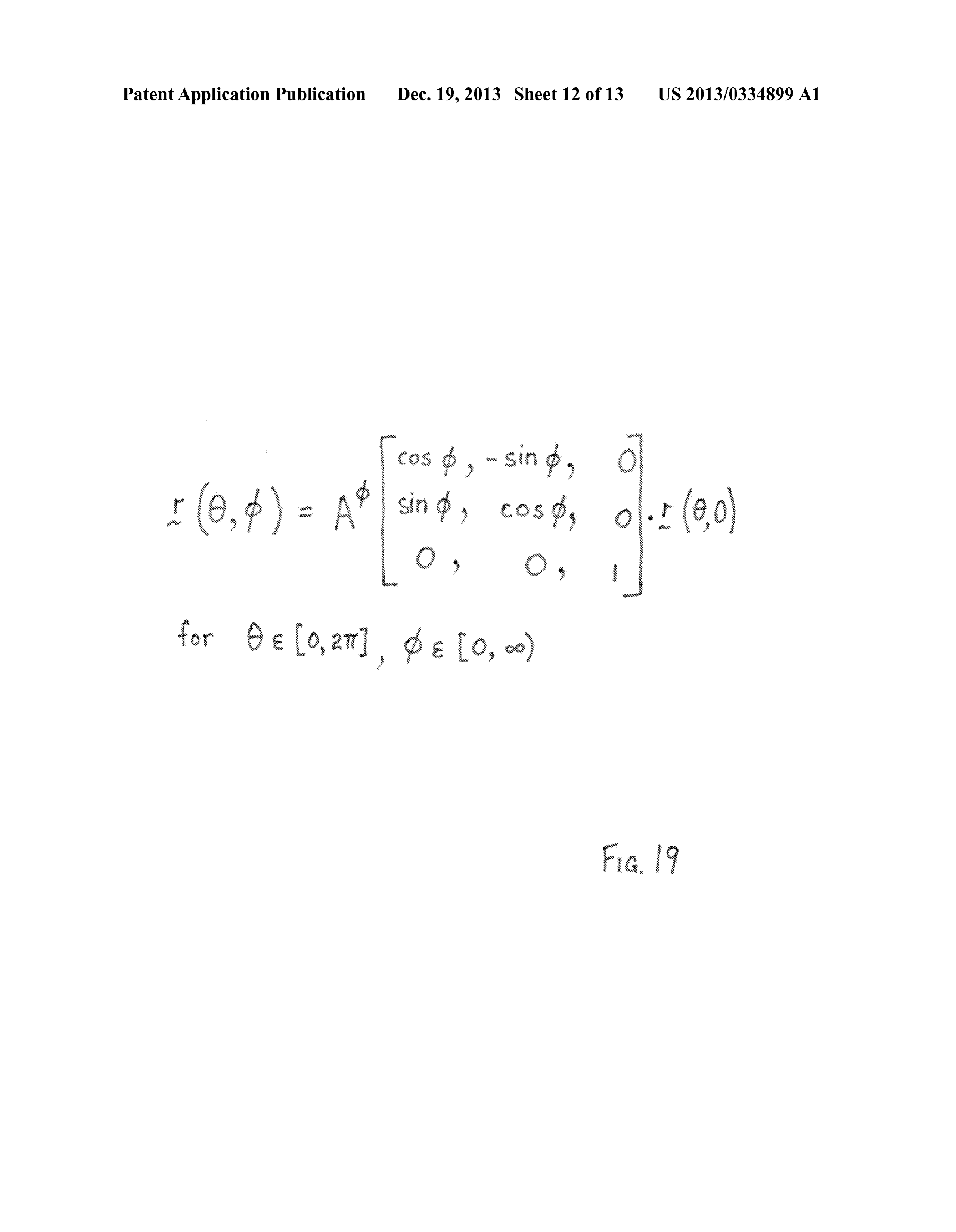
0046. The conduit 603 is preferably a portion of a gnomic exposing said conduit to a temperature difference to estab spiral known to mathematics and to biology in the formation lish a convective flow in said liquid through said conduit; of marine sea shells, for example. A typical form of Such a and gnomic spiral is illustrated in FIG. 18. A mathematical for exposing said liquid to a first magnetic field to align said mula for a gnomic surface is given in FIG. 19. Useful surfaces particles whilst within said first magnetic field, wherein are generated where the constant A is greater than Zero but a second magnetic field produced by said aligned less than 1. The vector r(0,0) is the shape of the generating dipoles moves relative to said coil to thereby generate an curve which is assumed to lie in the X-Z plane whilst the emf therein.
matrix corresponds to a simple rotation through the angle (p 2. The method of claim 1 wherein said exposing step com measured about the Z axis. The conduit 603 of FIG. 17 is a prises exposing at least part of said conduit to Solar radiation truncated and inverted form of the spiral illustrated in FIG. 18. or placing at least part of said conduit in thermal contact with 0047 FIG. 20 illustrates yet another generator similar to a body heated by solar radiation.
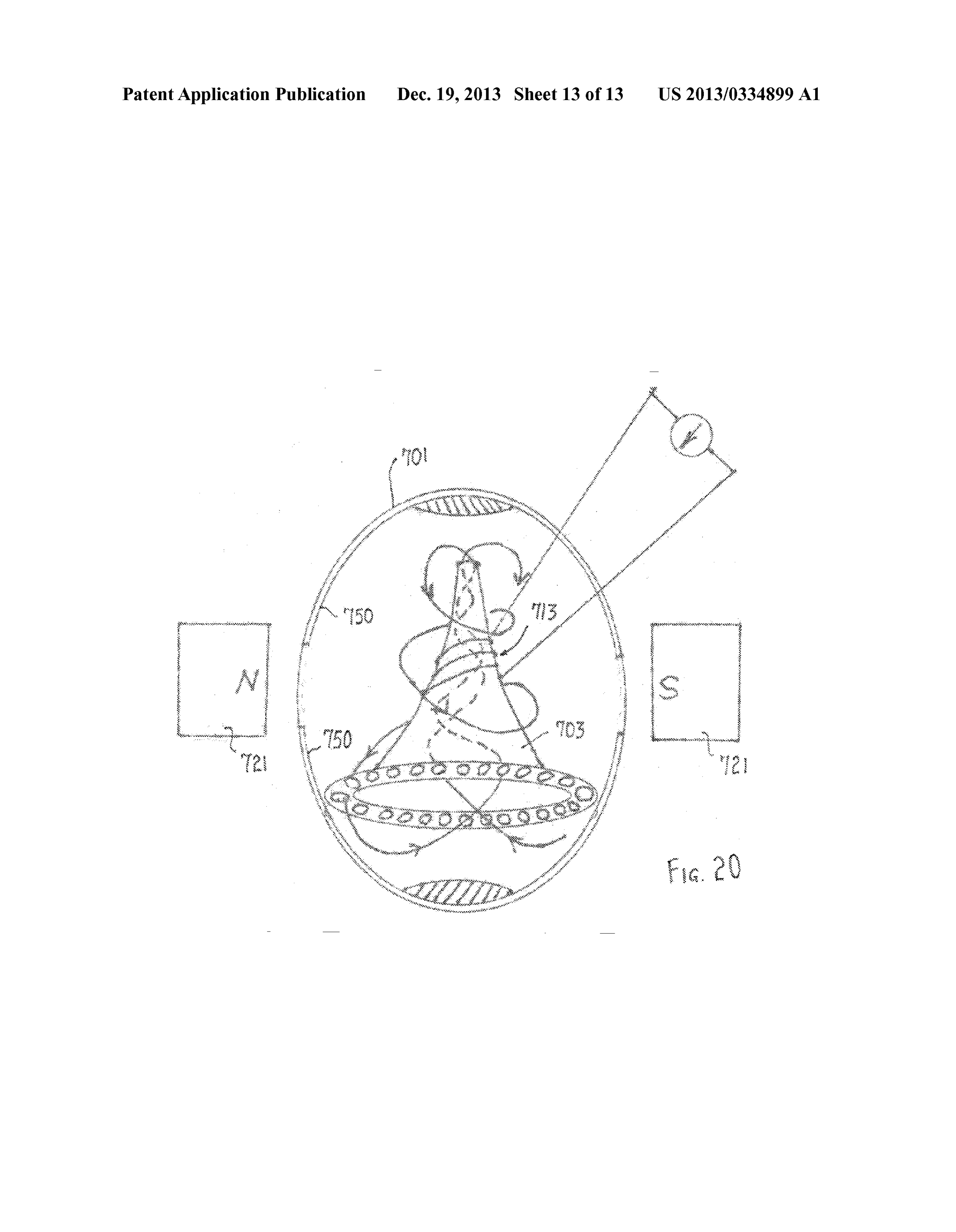
that of FIG. 17 save that the hollow ovoid 701 has an interior lining 750 of diamagnetic bismuth (except opposite the mag 3. The method of claim 1 further comprising the step of nets 721) and the conduit 703 has an elliptical horn shape forming said conduit into at least one substantially conical or about which the coil 713 is wound. The fluid moves in curved gnomic spiral.
paths indicated by the arrows in FIG. 20. 4. The method of claim 1 further comprising the step of 0048. It will be apparent to those skilled in the art that the alternating the direction of said first magnetic field. generators of FIG. 17 can be inverted and the roles of the heat 5. The method of claim 4 further comprising the step of Source and heat sink reversed, in which case the upwards generating said first magnetic field by a stack of permanent convective flow through the conduit 603 is indicated by bro magnets having alternating polarities. ken arrows in the inverted FIG. 17. 6. The method of claim 1 further comprising the step of 0049. To summarise, disclosed are a number of preferred forming said particles from particles of an oxide, chloride or features and concepts for generating electricity in accordance Sulphate of iron.
with embodiments of the present invention, including: 1) a 7. An apparatus for generating electricity, said apparatus temperature differential to drive via convective flow a fluid comprising:
comprised of particles which have magnetised magnetic a conduit formed into an endless loop and confining a dipoles coated with a surfactant and Suspended in a carrier liquid including particles having a magnetic dipole; fluid or a paramagnetic fluid comprised of particles which a coil wound around at least a portion of said conduit; have dipoles that become magnetic under the influence of an heat transfer means connected with said conduit to estab external magnetic field; 2) a vessel (or conduit in some of the lish a temperature difference in said conduit which embodiments) comprised of any continuously-varying establishes a convective flow in said liquid through said curved surface to influence the flow and acceleration of the particles of the fluid (the surface is a conduit in some embodi conduit; and ments and a continuously curved shape in others that facili a pair of magnetic poles between which extends a first tates the helicoidal movement of the fluid); 3) a coil to, in magnetic field to which said liquid is exposed to align response to the flow of the particles of the fluid, generate an magnetic dipoles of said particles whilst within said first emifinan external circuit; 4) a magnetic field comprised of the magnetic field, whereby a second magnetic field pro earth’s magnetic field and/oran auxiliary magnetic field pref duced by said aligned magnetic dipoles of said particles erably created by at least one pair of magnetic poles placed in moves relative to said coil to thereby generate an emf vicinity of apparatus; and 5) a diamagnetic material used on therein.
surfaces near flowing fluid or in fluid. 8. The apparatus of claim 7 wherein said heat transfer 0050. The foregoing describes only some embodiments of means comprises a heat exchanger.
the present invention and modifications, obvious to those 9. The apparatus of claim 8 wherein said heat exchanger is skilled in the electric generator arts, can be made thereto heated by solar radiation.
without departing from the scope of the present invention. 10. The apparatus of claim 7 wherein said conduit is 0051. For example, the heat exchanger 17 can constitute a formed into at least one substantially conical or gnomic spi conventional solar hot water heater. Similarly, instead of ral.
magnetite, the ferrofluid can contain or comprise paramag 11. The apparatus of claim 7 wherein said pair of magnetic netic iron chloride or iron sulphate. poles comprise one of a plurality of magnetic poles of alter 0052. The term “comprising (and its grammatical varia nating polarity.
tions) as used herein is used in the inclusive sense of “includ 12. The apparatus of claim 11 wherein said plurality of ing’ or “having and not in the exclusive sense of "consisting magnetic poles comprise a stack of permanent magnets hav only of. ing alternating polarities.
1. A method of generating electricity, said method com 13. The apparatus of claim 7 wherein said particles are prising the steps of:
confining a liquid including particles having a magnetic formed from particles of an oxide, chloride or sulphate of iron.
dipole to a conduit formed into an endless loop;
winding a coil around at least a portion of said conduit;
Provenance
- Collection
- Patents citing this work
- Pages
- 17
- Method
- pdftotext (the PDF's own text layer) + pdftoppm 300dpi page scans
- Patent office record
- patents.google.com →
- Source
- Google Patents citing-documents table
- Assignee
- Benjamin Francis John Hallgren
- Inventors
- Susan MOTISSE
- Published
- 2013-12-19
- Transcribed from
- patentimages.storage.googleapis.com →