patent · US6146518
Pressure differential control in an electrolytic cell
14 November 2000
Page 1 — bibliographic record
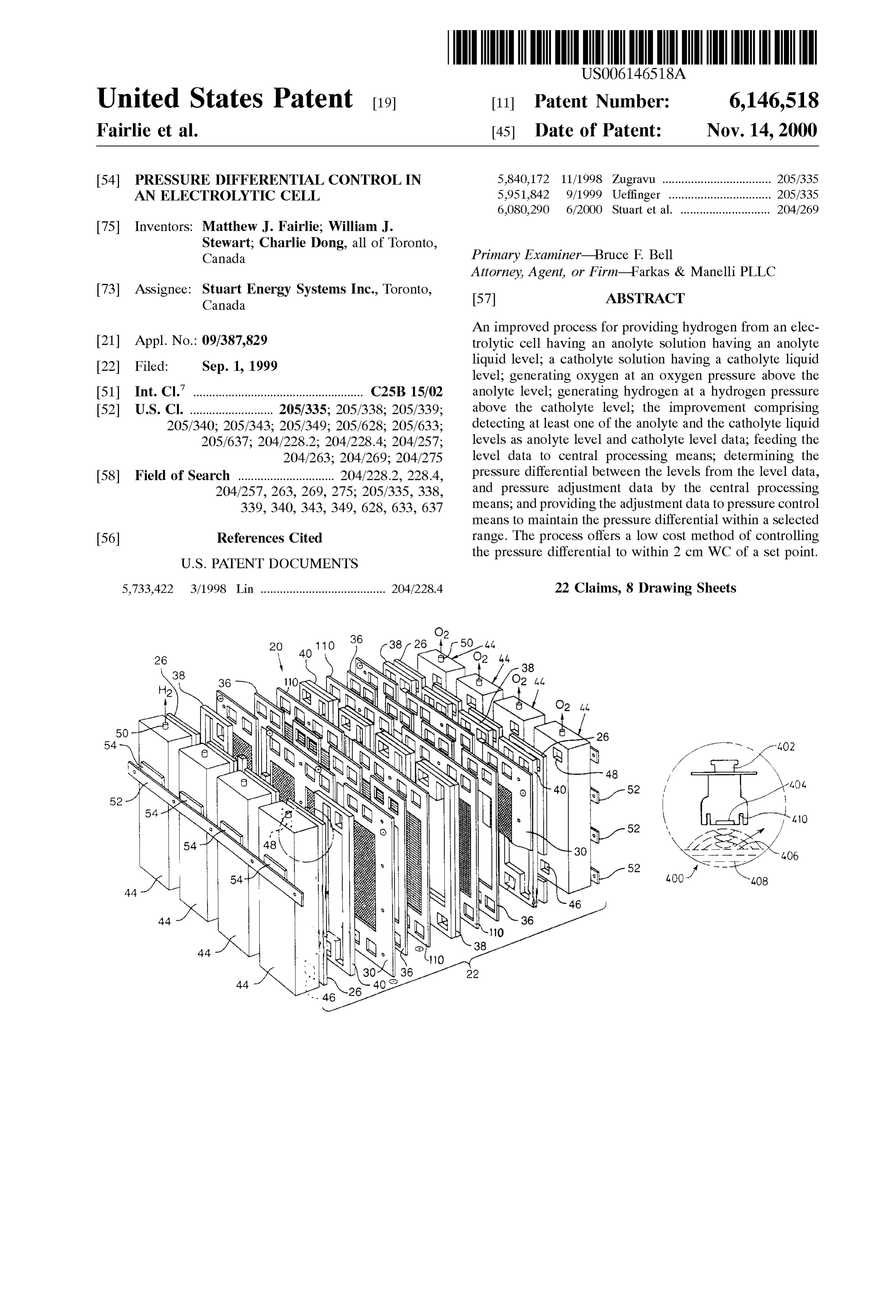
United States Patent (19) 11 Patent Number: 6,146,518 Fairlie et al. (45) Date of Patent: Nov. 14, 2000 54 PRESSURE DIFFERENTIAL CONTROL IN 5,840,172 11/1998 Zugravu .................................. 205/335 AN ELECTROLYTIC CELL 5,951,842 9/1999 Ueffinger ... ... 205/335 6,080,290 6/2000 Stuart et al. ............................ 204/269 75 Inventors: Matthew J. Fairlie; William J.
Stewart; Charlie Dong, all of Toronto,
Canada Primary Examiner Bruce F. Bell
Attorney, Agent, or Firm-Farkas & Manelli PLLC 73 ASSignee: Star Energy Systems Inc., Toronto, 57 ABSTRACT An improved process for providing hydrogen from an elec 21 Appl. No.: 09/387,829 trolytic cell having an anolyte Solution having an anolyte 22 Filed: Sep. 1, 1999 liquid level; a catholyte Solution having a catholyte liquid e --9 level; generating oxygen at an oxygen pressure above the (51) Int. Cl." ..................................................... C25B 15/02 anolyte level; generating hydrogen at a hydrogen pressure 52 U.S. Cl. .......................... 205/335; 205/338; 205/339; above the catholyte level; the improvement comprising 205/340; 205/343; 205/349; 205/628; 205/633; detecting at least one of the anolyte and the catholyte liquid 205/637; 204/228.2; 204/228.4; 204/257; levels as anolyte level and catholyte level data, feeding the 204/263; 204/269; 204/275 level data to central processing means, determining the 58 Field of Search .............................. 204/2282,228.4, pressure differential between the levels from the level data, 204/257, 263,269, 275; 205/335, 338, and pressure adjustment data by the central processing 339, 340, 343, 349, 628, 633, 637 means, and providing the adjustment data to pressure control means to maintain the pressure differential within a Selected 56) References Cited range. The process offers a low cost method of controlling
the pressure differential to within 2 cm WC of a set point.
5,733,422 3/1998 Lin ....................................... 204/228.4 22 Claims, 8 Drawing Sheets
Page 2
Drawing sheet — no readable text.
Page 3
Drawing sheet — no readable text.
Page 4
Drawing sheet — no readable text.
Page 5
Drawing sheet — no readable text.
Page 6
Drawing sheet — no readable text.
Page 7
Drawing sheet — no readable text.
Page 8
Drawing sheet — no readable text.
Page 9
Drawing sheet — no readable text.
Page 10
PRESSURE DIFFERENTIAL CONTROL IN Supported within a cell Stack configuration. The latter further AN ELECTROLYTIC CELL comprises a Series of components Such as circulation frames and gaskets through which aqueous electrolyte is circulated
FIELD OF THE INVENTION and product disengaged. The cell further includes a separator assembly having appropriate means for Sealing and
This invention relates to electrolytic cells, particularly to mechanically Supporting the Separator within the enclosure water electrolytic cells for the production of hydrogen and and an end wall used to Separate adjacent cells blockS. oxygen and more particularly, to control of the preSSure Multiple cells may be connected either in Series or in parallel differential across the cell membrane/Separator. to form cell Stacks and there is no limit on how many cells may be used to form a Stack. A cell block is a unit that
BACKGROUND TO THE INVENTION comprises one or more cell Stacks and multiple cell blockS Electrosynthesis is a method for the production of chemi PCT are connected together by an external bus bar. Aforesaid application WO98/29912 describes functional elec cal reaction(s) that is electrically driven by passage of an trolysers comprising one or more cells that are connected electric current, typically a direct current (DC), in an elec together either in parallel, in Series, or a combination trochemical cell through an electrolyte between an anode 15 thereof.
electrode and a cathode electrode from an external power Depending on the configuration of Such a cell Stack Source. The rate of production is proportional to the current electrochemical System, each includes an end box at each flow in the absence of parasitic reactions. For example, in a end of each Stack in the Simplest Series configuration or a liquid alkaline water electrolysis cell, the DC current is collection of end boxes attached at the end of each cell passed between the two electrodes in an aqueous electrolyte block. Alternative embodiments of an electrolyser includes to split water, the reactant, into component product gases, end boxes adapted to be coupled to a horizontal header box namely, hydrogen and oxygen where the product gases when both a parallel and Series combination of cells are evolve at the Surfaces of the respective electrodes. assembled.
Water electrolysers have typically relied on preSSure con 25 In the operation of the cell Stack during electrolysis of the trol Systems to control the pressure between the two halves electrolyte, the anode Serves to generate oxygen gas whereas of an electrolysis cell to insure that the two gases, namely, the cathode Serves to generate hydrogen gas. The two gases oxygen and hydrogen produced in the electrolytic reaction are kept Separate and distinct by a low gas permeable are kept Separate and do not mix. membrane Separator. Some desirable properties of Separa In the conventional mono-polar cell design in wide com tors include: high electrical resistivity, low ionic resistivity, mercial use today, one cell or one array of (parallel) cells is low gas permeability, good mechanical integrity, and low contained within one functional electrolyser, cell COSt.
compartment, or individual tank. Each cell is made up of an The flow of gases and electrolytes within cells are con assembly of electrode pairs in a separate tank where each ducted via circulation frames and gasket assemblies which assembly of electrode pairs connected in parallel acts as a 35 also act to Seal one cell component to a Second and to contain Single electrode pair. The connection to the cell is through a the electrolyte in a cell Stack configuration in analogy to a limited area contact using an interconnecting bus bar Such as tank.
that disclosed in Canadian Patent No. 302,737, issued to A. The rigid end boxes can Serve Several functions which T. Stuart (1930). The current is taken from a portion of a include providing a return channel for electrolyte flowing cathode in one cell to the anode of an adjacent cell using 40 out from the top of the cell in addition to Serving as a point-to-point electrical connections using the above gas/liquid Separation device. The end box may also provide mentioned bus bar assembly between the cell compartments. a location for components used for controlling the electro The current is usually taken off one electrode at Several lyte level, Such as, liquid level Sensors and temperature, i.e. points and the connection made to the next electrode at for example heaters, coolers or heat eXchangers. In addition, Several points by means of bolting, welding or Similar types 45 with appropriate Sensors in the end boxes individual cell of connections and each connection must be able to pass Stack electrolyte and gas purity may be monitored. Also, Significant current densities. while most of the electrolyte is recirculated through the Most filter press type electrolysers insulate the anodic and electrolyser, an electrolyte Stream may be taken from each cathodic parts of the cell using a variety of materials that endbox to provide external level control, electrolyte density, may include metals, plastics, rubbers, ceramics and various 50 temperature, cell pressure and gas purity control and moni fibre based Structures. In many cases, O-ring grooves are toring. This Stream is returned to either the same end box or machined into frames or frames are moulded to allow mixed with other similar Streams and returned to the end O-rings to be inserted. Typically, at least two different boxes. Alternatively, probes may be inserted into the end materials from the assembly are necessary to enclose the boxes to control these parameters. An end box may also have electrodes in the cell and create channels for electrolyte 55 a conduit to provide the two phase mixture to the existing circulation, reactant feed and product removal. liquid in the end box to improve gas liquid Separation. End WO98/29912, published Jul. 9, 1998, in the name of The boxes of like type containing the same type of gas can be Electrolyser Corporation Ltd. and Stuart Energy Systems connected via a header Such that they share a common Inc., describes Such a mono-polar cell electrolyser System electrolyte level.
configured in either a Series flow of current, in a Single Stack 60 One prior art pressure control System provides a water electrolyser (SSE) or in a parallel flow of current in a Seal to equalize pressure in the two halves of the cell. This multiple stack electrolyser (MSE). Aforesaid WO98/29912 is the approach most often followed in “home-made” elec provides details of the components and assembly designs for trolysers. Typically, the water Seal is a couple of inches deep both SSE and MSE electrolysers. and So the cell operates a couple of inches WC pressure AS used herein, the term "cell' or “electrochemical cell” 65 above atmospheric.
refers to a structure comprising at least one pair of electrodes An alternative System provides a membrane Separator including an anode and a cathode with each being Suitably which can Sustain a pressure difference between the two
Page 11
halves of the cell without gas mixing. The PEM cell is the catholyte halves of the cell in a pressurized alkaline cell best example of this type of system. The PEM cell can which is able to control the pressure difference between the Sustain up to a 2500 psi pressure difference without signifi parts of the cell to within +2 cm WC of the set point. cant loss of gas purity. In one aspect, the invention provides a method of con A third is an active control System which Senses pressure trolling pressure between the oxygen and hydrogen com and controls the outflow of gases from the two cells. Control partments of an electrolytic cell, particularly a water can be achieved in one of two ways: by a mechanical System electrolyser, between a desired range of pressure differential which relies on pressure regulators, Such as a dome-loaded values, particularly below a Selected maximum value, by flow regulator to control pressure between the two cells detecting anolyte liquid level and/or catholyte liquid level to which, for example, might employ the oxygen pressure as a better than 2 cm. In consequence of the measured preSSure reference pressure to regulate the pressure in the hydrogen differential, adjustment of the pressure of one compartment half of the cell; and by an electronic system which relies on relative to another to bring the pressure differential within measurement of the difference in gas pressure between the the accepted range is then carried out. In a preferred two cell to control the rates of gas outflow from the two sides embodiment, continuous measurement of the pressure dif of the cell So as to maintain a desired pressure difference of 15 ferential is made and fed to a controller having algorithmic usually Zero or with the hydrogen Side slightly higher. control means which instruct a compensating means to be Typically, however, for very Small commercial hydrogen activated as required to provide the desired preSSure differ generators (0.1 Nm/h) PEM type electrolysis cells are ential. The compensating means may comprise, for example, favoured. Although the cost of the cell is far higher than for a variable opening oxygen control valve which, on cell alkaline electrolysers, these costs are more than offset by the Start-up, is Set to provide a pre-Set oxygen pressure. A controls needed for the alkaline Systems using mechanical or preSSure differential value which can include Zero can be Set electronic actuators, and by the need for higher pressures and measured very precisely, preferably, to a fraction of a cm and, hence, compression in electrolysers using a water Seal water column. The practice of the invention is of value in not preSSure control System. being dependent on the absolute cell pressure Set point. 25 Control can be achieved to a specific pressure differential
Control Systems that rely on mechanical actuators are difficult to calibrate and ensure “close to Zero” pressure level difference.
difference on a pressurized cell. In the case of a Stuart cell, Accordingly, in one aspect, the invention provides an one needs to ensure that the pressure difference doesn't force improved process for providing hydrogen from an electro a level difference large enough to expose one side of the cell lytic cell having:
to the gas phase of the opposite Side of the cell as this will an anolyte Solution having an anolyte liquid level; reduce cell efficiency or may result in poor gas purity. a catholyte Solution having a catholyte liquid level; Electrolysers that rely on mechanical actuators typically generating oxygen at an oxygen pressure above Said have a 1 atmosphere or So pressure difference between the anolyte level;
two Sides of the cell. Gas purity is maintained by, for 35 generating hydrogen at a hydrogen preSSure above Said example, a woven asbestos or a needle felted polyphenylene catholyte level;
sulphide (PPS) membrane. the improvement comprising
Control Systems which rely on electronic actuatorS Suffer (a) detecting at least one of Said anolyte and said from the weakness that in order to maintain level differences catholyte liquid levels as anolyte level and catholyte between the two sides in the cell within an inch of height, 40 level data;
which is required to insure that the membrane is covered on (b) feeding said level data to a central processing both sides, Sophisticated high resolution pressure measure meanS, ments are needed. The demands of the measurement and control System are put in perspective when we consider (c) determining the pressure differential between said controlling pressure to 2 cm WC in a cell pressurized to 7 45 levels from Said level data, and pressure adjustment bars or 7000 cm WC. data by Said central processing means, and (d) providing said adjustment data to pressure control
It would be advantageous to provide prior art electrolyser means to maintain Said pressure differential within a Systems with a simple, low cost, in Situ level control monitor Selected range.
that can be utilized for systems control. This would elimi Most preferably, the aforesaid process continuously, nate the need for complex, expensive preSSure measuring 50 Sequentially carries out steps (a)-(d), wherein the pressure Systems that must retains their integrity in a hostile proceSS differential is submitted to an algorithmic treatment by the environment of elevated temperature of, for example, central processing means to determine the pressure adjust 30-100° C. and concentrated alkali environments of, say, ment data to better define the adjustment data. 20-40 wt % KOH. By the term “continuous” is meant that the moment(s) any It is most important that the liquid levels pressure differ 55 and all changes in liquid(s) level(s) is detected by the ential be maintained within well-defined limits in order to detection means, the change(s) is computed to provide reduce the risk of intermixing of product gases, namely, instant action by the adjustment means. If Safe operation is hydrogen and oxygen acroSS the membrane, and to ensure between set points AB, then at A+AX and A+Ax' where proper fluid management to permit Safe and functional A<A+AX, A+Ax'<B, it may be desired that the controller operation of the electrolysis cell. 60 takes no action, i.e. a deadband is permitted. However, there remains a need for a relatively low cost In one embodiment, a simple Spring-loaded check valve and reliable method of controlling pressure in a pressurized controls the outflow from the oxygen side of the cell and electrolyser. maintains cell pressure at the value Set by the check valve.
SUMMARY OF THE INVENTION
The pressure of the check valve can be adjusted to Set the 65 maximum pressure needed in a particular application. On
It is an object of the present invention to provide a low the hydrogen Side, a variable flow control valve either opens cost method of controlling preSSure between the anolyte and or closes to regulate the flow of hydrogen gas from the
Page 12
S 6 outtake. The level of the electrolyte measured in the anode nection of four Stacks consisting of two cells each connected and cathode compartments determines the preSSure differ in parallel according to the prior art; ence between the two sides of the cell. The measured level FIG. 2 is a perspective exploded view of a two cell Single difference is compared with a level difference Set point and Stack electrolyser (SSE) according to the prior art; the error is used to adjust the Setting of the hydrogen control FIG. 3 is a perspective, exploded view, in part, of an MSE valve.
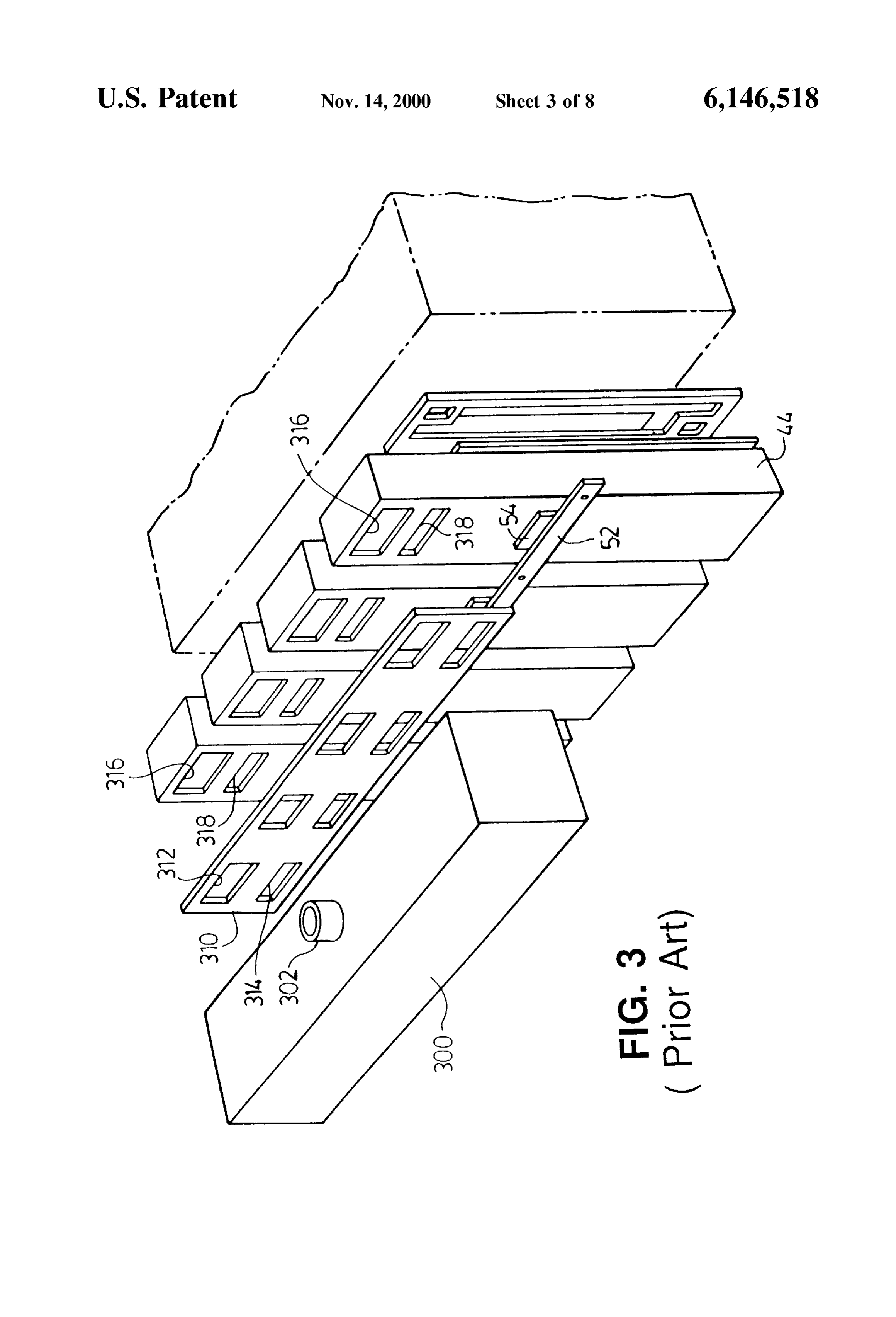
electrolyser having a plurality of end boxes and a headerbox
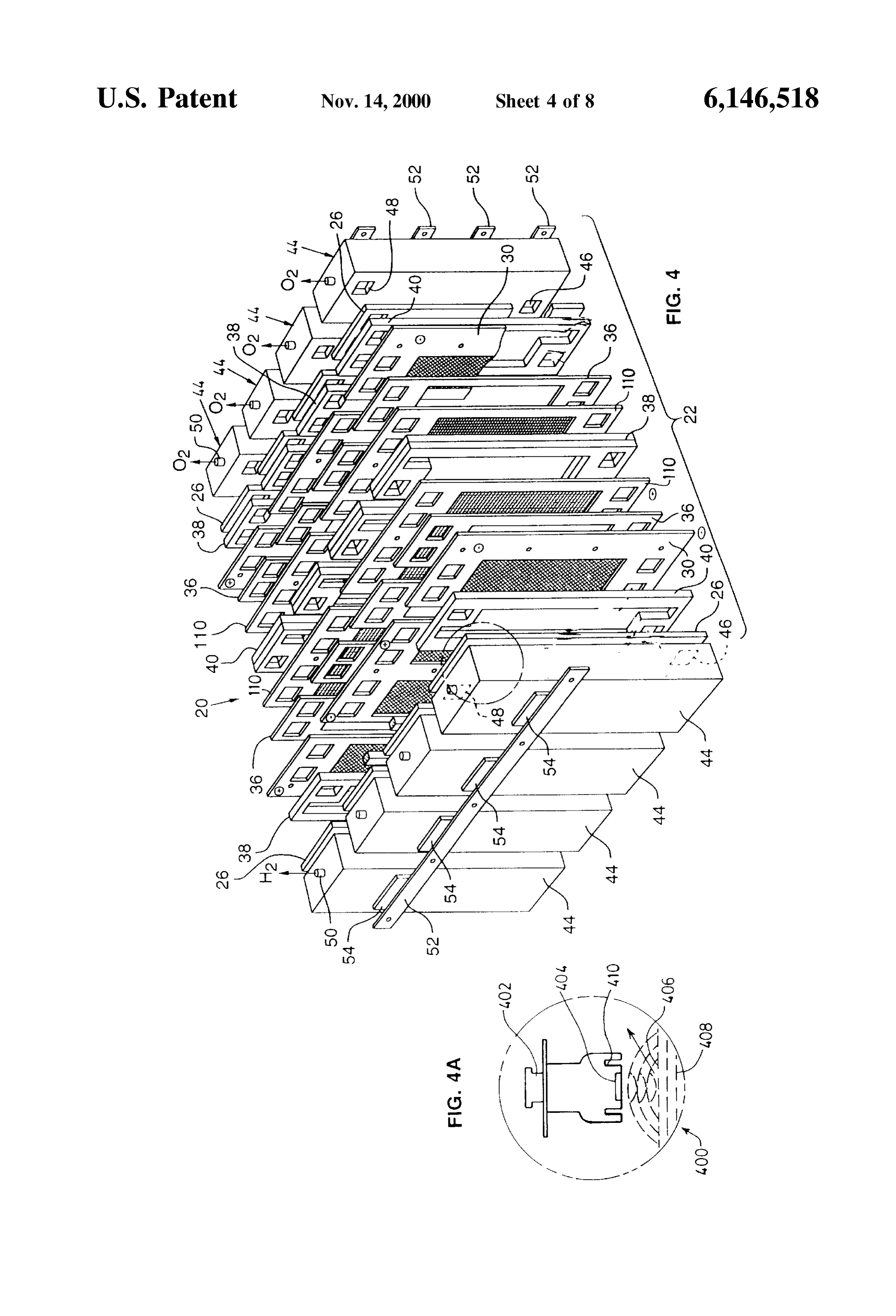
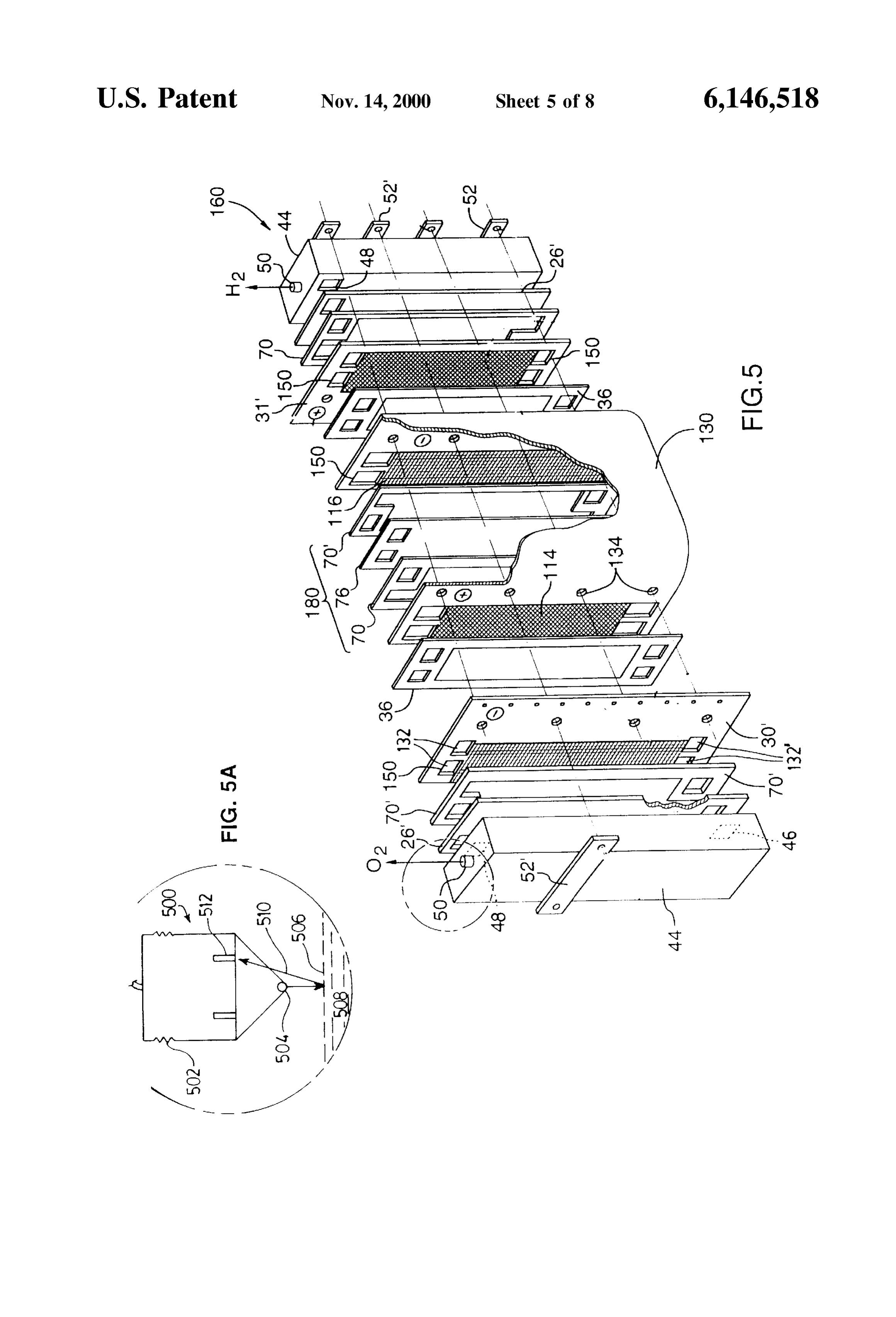
In alternative embodiments according to the invention one according to the prior art, or more of the liquid levels may be detected, for example, by optical Sensing means, electrical or electromagnetic genera FIG. 4 (with insert FIG. 4A) is an exploded perspective tion and Sensing means, ultraSonic generation and Sensing view of a multiple stack electrochemical system (MSE) means or combinations, thereof. consisting of the Series connection of four Stacks consisting The aforesaid methods of pressure control according to of two cells each connected in parallel according to the the invention are well Suited for coupling electrolyser cells invention having an ultraSonic level Sensor; to a continuously operating compressor where gas pressure FIG. 5 (with insert FIG. 5A) is perspective exploded view at the Suction of the compressor is maintained by a recir 15 of a two cell Single Stack electrolyser (SSE) according to the culation loop connecting discharge to Suction through a invention having an optical Sensor;
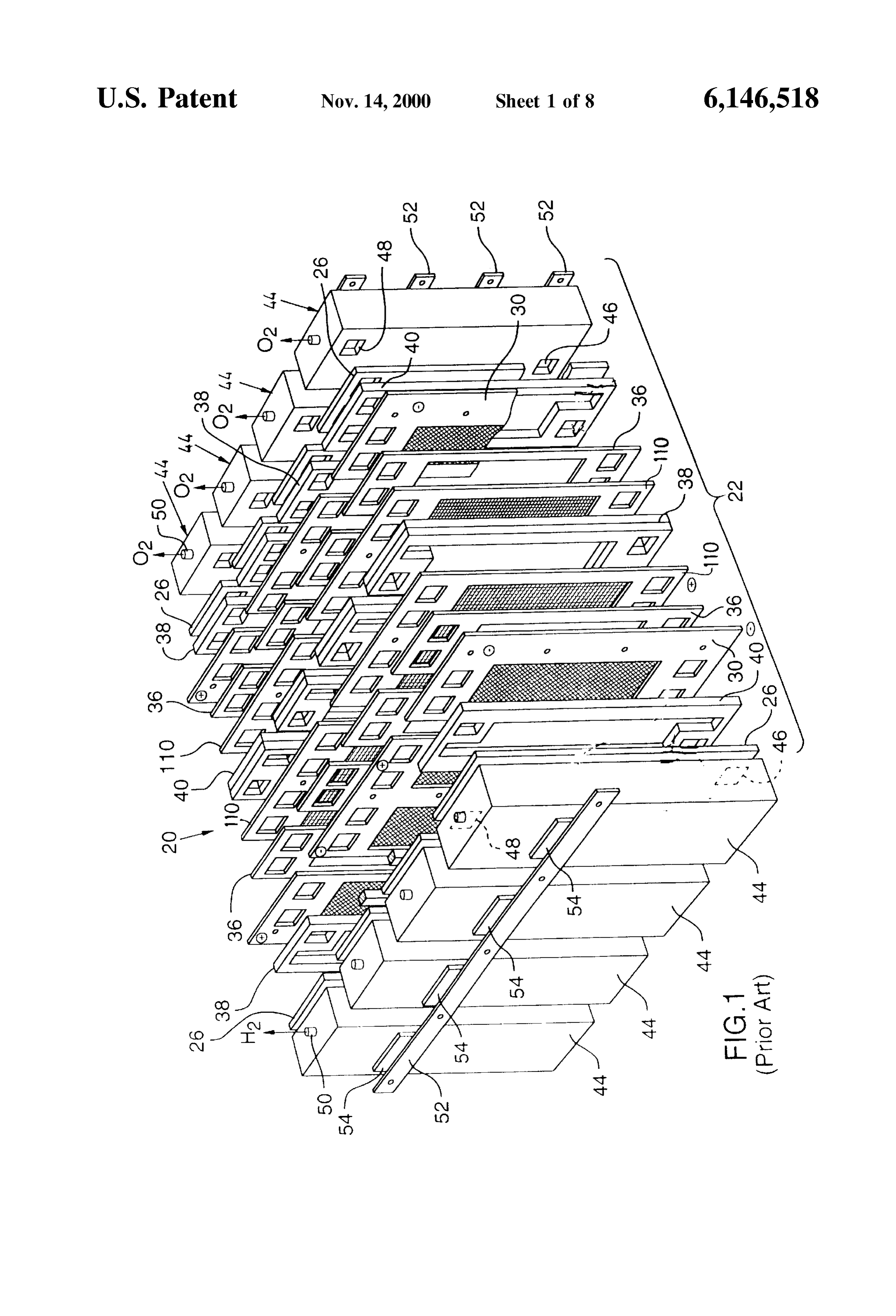
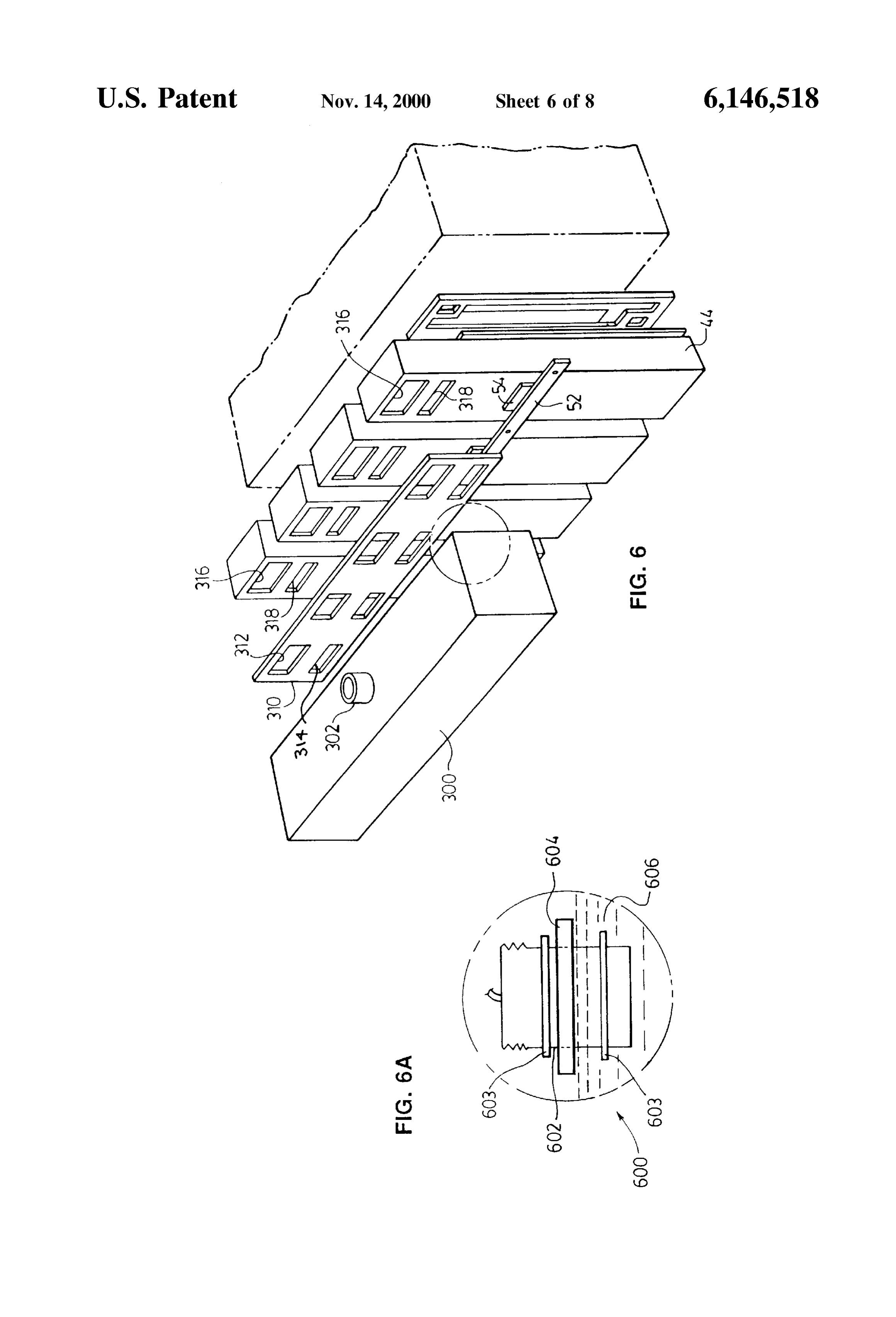
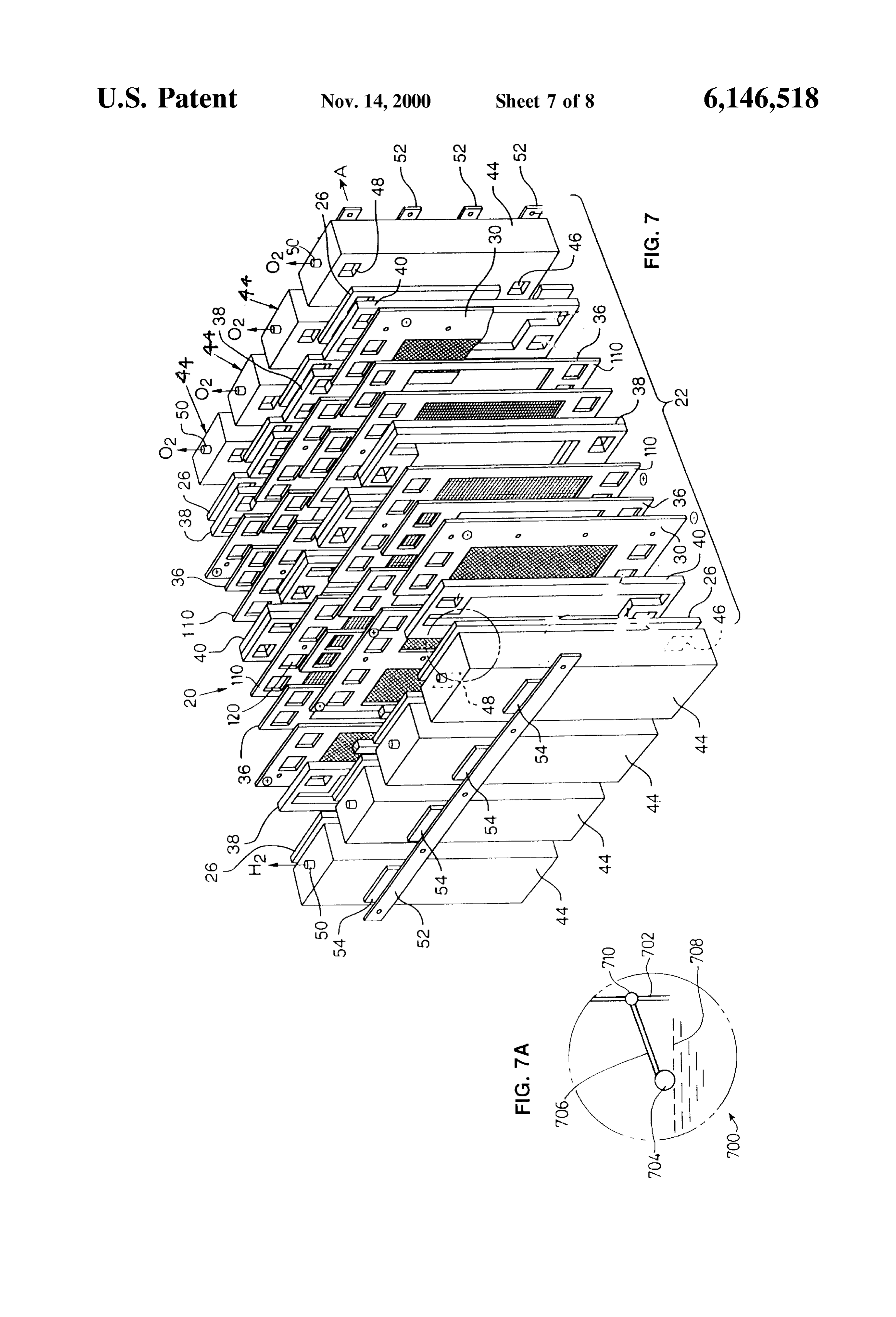
preSSure regulator that maintains the Suction at a constant FIG. 6 (with insert FIG. 6A) is a perspective, exploded elevated pressure. view, in part, of an MSE electrolyser having a plurality of The present invention can be used on Single cells or on end boxes and a header box according to the invention Stacks of cells that use end boxes where-in the gas off-takes having an electrical/electromagnetic Sensor; are located. Further, it can also be used on Stacks of cells FIG. 7 (with insert FIG. 7A) is an exploded perspective interconnected to form cell blocks by means of a header, view of a multiple stack electrochemical system (MSE) wherein gas/liquid mixtures are discharged and the electro consisting of the Series connection of four Stacks consisting lyte level is controlled at Some desired height. of two cells each connected in parallel according to the Thus, the term “electrolytic cell” as used in this specifi 25 invention having a mechanical float liquid level detector; cation and claims includes the practice of the invention FIG. 8 is a logic block diagram of the direct level control wherein the detection of the anolyte and/or catholyte levels Sensor logic illustrating detection, control and adjustment is effected within the cell perse, endboxes and/or associated features of use in one embodiment according to the inven headers. tion; and wherein the same numerals denote like parts. The present invention provides for cost effective alkaline preSSurized water electrolysers that could be used in a host DETAILED DESCRIPTION OF PREFERRED of energy and industrial applications and which does not EMBODIMENTS require the use of Water Seals. FIG. 1 shows generally as 20 a monopolar MSE according In a further aspect, the invention provides an improved to the prior art as embodiment in aforesaid WO98/29912. electrolytic cell for the production of hydrogen comprising 35 an anolyte Solution having an anolyte liquid level; Electrochemical system 20 is shown as a cell block a catholyte Solution having a catholyte liquid level; comprising four cell StackS 22 with Series connections between cell Stacks and the two electrolysis cells of each generated oxygen at an oxygen preSSure above Said Stack connected in parallel.
anolyte level; 40 Each stack 22 comprises two cells having two anodes 110 generated hydrogen at a hydrogen preSSure above Said and two cathodes 30. In each compartment an anolyte frame catholyte level; 38 is located adjacent to anodes 110 to define an anolyte the improvement comprising chamber and a catholyte frame 40 is located adjacent to (i) detection means for detecting at least one of Said cathodes 30 defining a catholyte chamber. Anolyte frame 38 anolyte and Said catholyte levels as anolyte level data 45 is essentially identical in structure to catholyte frame 40 and and catholyte level data; may be generally referred to as electrolyte circulation (ii) central processing means; frames.
(iii) means for feeding said level data to said central Each anode and cathode chamber in a given cell is processing means to determine the preSSure differ Separated by a separator 36 to reduce mixing of the different ential between Said levels from Said level data, and 50 electrolysis products, namely oxygen and hydrogen, pro preSSure adjustment data; and duced in the respective anode and cathode chambers. (iv) pressure control means to receive said adjustment Electrochemical system 20 includes an end box 44 at each data and adjust at least one of Said oxygen pressure end of each Stack 22. Referring Specifically to FIG. 1, each and hydrogen pressure to maintain Said pressure endbox 44 is provided with a lower aperture 46 and an upper differential within a Selected range. 55 aperture 48 in the side of the box in communication with the In preferred embodiments, the electrolytic cell according respective anolyte or catholyte chamber. A gas outlet 50 at to the invention comprises optical Sensing means, electrical the top of each box 44 provides an outlet for collecting the or electromagnetic generation and Sensing means, ultrasonic respective gas involved during the electrolysis reaction. Cell generation and Sensing means or combinations, thereof. stacks 22 and entire cell block 20 are held together with 60 Sufficient force So that a fluid tight Seal is made to prevent
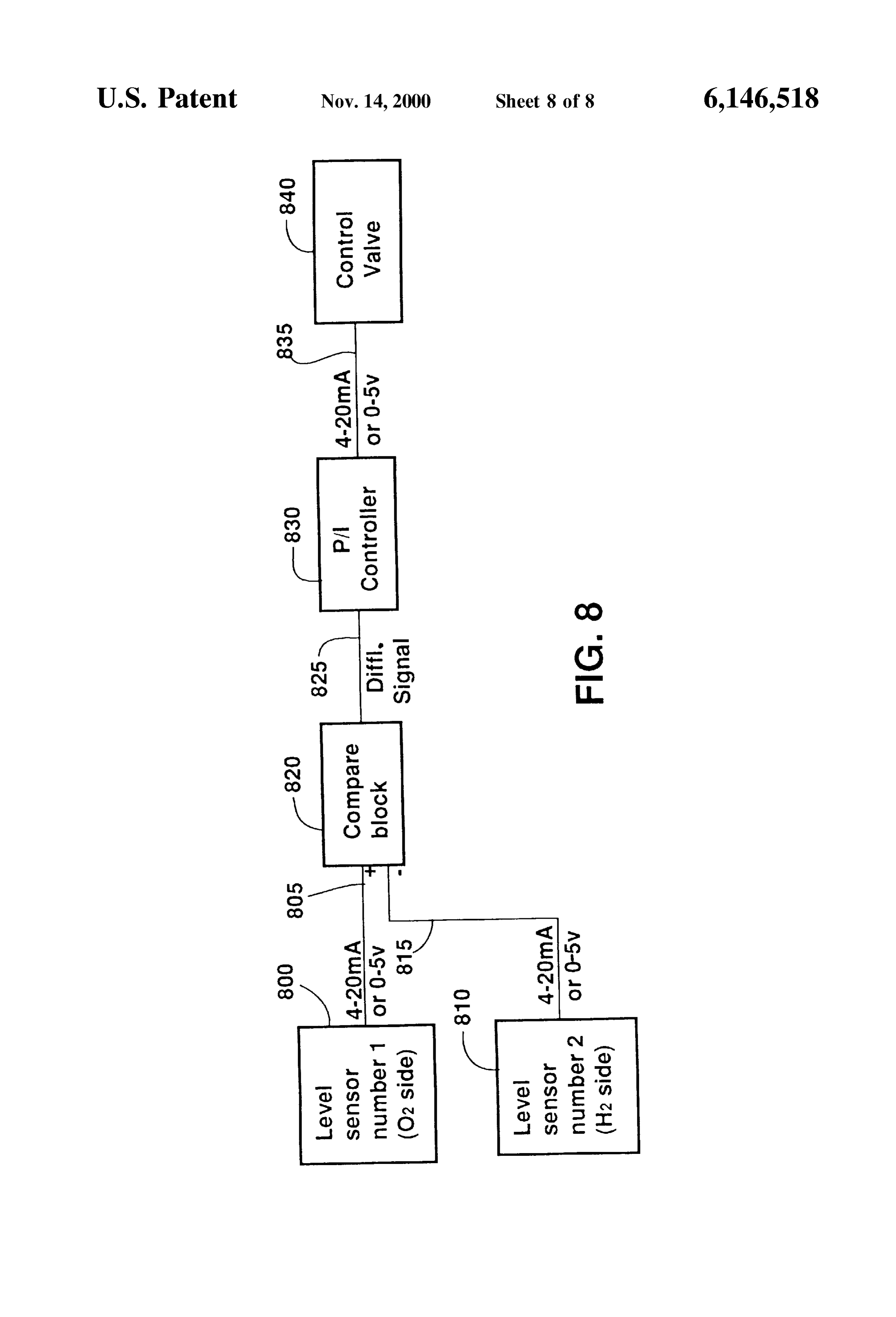
BRIEF DESCRIPTION OF THE DRAWINGS
leaking of electrolyte or gases. The use of a rigid structural
In order that the invention may be better understood, element Such as a rectangular tube used to form end box 44 preferred embodiments will now be described by way of with clamping bars 52 and tie rods and asSociated fasteners example only, with reference to the accompanying drawings, (not shown) provides an even load distributing Surface to wherein 65 Seal the StackS 22 at modest clamping preSSures. Electrically FIG. 1 is an exploded perspective view of a multiple Stack insulating panels 54 are Sandwiched between the outer electrochemical System (MSE) consisting of the Series con surfaces of end boxes 44 and clamping bars 52 in order to
Page 13
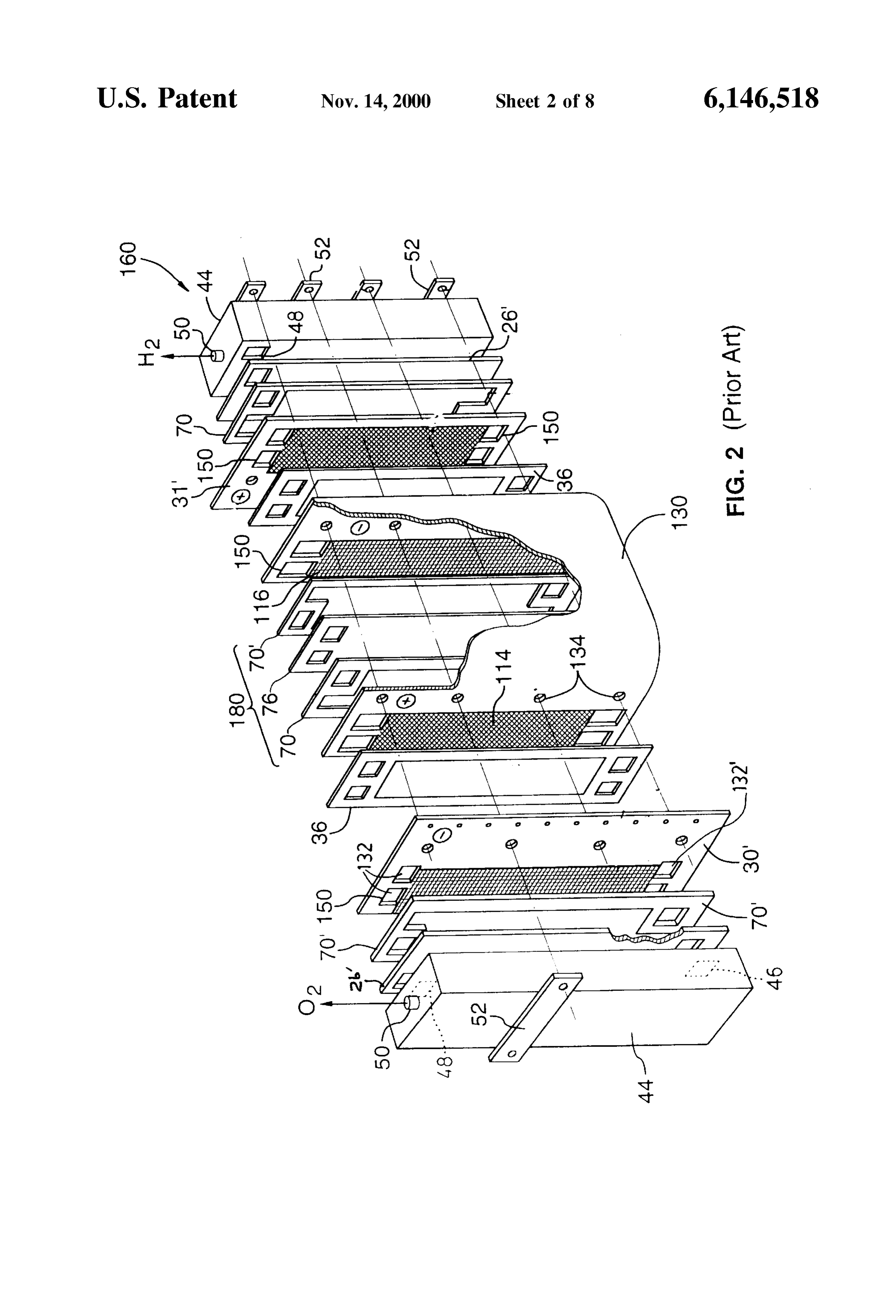
prevent the end boxes from being electrically connected to Generator/sensor 400 provides a sound wave via a direct each other by the clamping bars. mechanical vibration or via an induced mechanical vibration An insulating planar gasket 26 is disposed at the end of by conversion of an electrical Signal into a mechanical each stack between electrolyte frames 38 or 40 and end displacement by means of piezoelectric unit 404. Unit 404 boxes 44 for insulating the face of end box 44 from contact generates a Source Signal which is reflected from Surface 406 with electrolyte. Gasket 26 is provided with an upper of electrolyte 408 and detected by sensing ring 410. The aperture and a lower aperture (not shown) in registration frequency, amplitude and phase shift between the Source and with apertures 48 and 46, respectively, in end box 44 for return Signal can be used to compute the liquid level within fluid circulation. t2 cm of the Selected Set point. It will be understood that known electrochemical systems With reference to FIG. 5, this shows an optical level may be modified to include the end boxes disclosed herein sensor generally as 500 retained in the SSE of FIG. 2 by by way of retrofit. screw-threads 502. Level sensor 500 generates a fine, coher For electrolysis cells used in electroSynthesis, a liquid can ent Source of light of a given wavelength which is trans be fed forward from one cell block to the next cell block mitted from lower tip 504 to a reflecting surface 506 through 15 electrolyte 508. The refracted beam 510 is detected by a between adjacent boxes in order to assist conversion per pass. End boxes 44 may be manufactured form a variety of photomultiplier 512. The frequency, wavelength, intensity, material Suitable for alkaline or acid based electrochemical phase shift and refraction of the light beam is used to Systems including Steel, StainleSS Steel, nickel or plastics compute the liquid level on a continuous basis. with, if necessary, appropriate reinforcements. FIG. 6 shows the header box 300 of FIG. 3 having an FIG. 2 shows a prior art configuration of an electrochemi electrical/electromagnetic Sensor shown generally as 600. cal System shown generally as 160 referred to as the Single Sensor 600 comprises a float/reed Switch having a right Stack electrochemical System (SSE) configuration which is Vertical cylindrical body 602 having an electromagnetic core characterized by the fact that two or more cell compartments retained between rings 603 and a float 604 having a density are placed one behind another to form a Succession or 25 of less than that of electrolyte 606.
“String', of cell compartments connected electrically in Float 604 moves up and down on the electrolyte surface Series. The electrical connection between cells is made using with a change in the electrolyte level So as to translate the a folded double electrode plate 130 so that current passes relative position of float 604 with central body 602. Either around the edge of insulating panel constituting an end wall float 604 or body 602 can act as the primary and/or second 76. The anolyte frames 70 and catholyte frames 70' are ary pole of a magnet. The relative displacement yields a identical to the corresponding electrolyte frames 38 and 40 charge in the magnetic field (flux) which is sensed and of FIG. 1. Each cell is separated from adjacent cells by an converted to an electric Signal to reflect the liquid level. electrolyte frame assembly 180 formed by sandwiching FIG. 7 shows the end box 44 of FIG. 1 having a mechani liquid impermeable panel 76 between the two frames. Exter cal level ball cock sensor shown generally as 700 affixed to nal contact from the power Supply (not shown) to the 35 end box 44 at an upper part of wall 702. Sensor 700 has a electrochemical System 160 is made to Single plate elec float 704 and lever 706. Changes in the electrolyte level 708 trodes 30' and 31'. translate into changes in the position of float 704 through a Electrochemical system 160 in FIG. 2 comprises two cells defined arc, Such that its relative position can be determined having one double electrode plate 130 and two single plate by an electrical or mechanical transducer 710 So as to reflect electrodes 30' and 31' with one being located at each end of 40 the electrolyte level.
the stack. It will be understood that for a SSE with three With reference to FIG. 8, level sensor number 1, shown as cells, two double electrode plates 130 would be required, for 800 is suitably positioned in the anolyte portion of the cell an SSE with four cells, three double electrode plates would to detect, measure and determine the instantaneous value of be required and So on. An insulating panel 26' is used at the the anolyte level in the cell. Sensor 800 provides a data ends of the Stack adjacent to the endboxes 44. Anolyte frame 45 Signal output proportional to the magnitude of the anolyte 70, catholyte frame 70' and inter-cell panel 76 are sand level in the form of either a current (4-20 mA) or voltage wiched between the anode section 114 and cathode section (0-5V) signal along line 805. Simultaneously, level sensor 116 in the assembled electrolyser. Double electrode plate number 2, shown as 810 is positioned in the catholyte 130 is provided with two upper apertures 132 and two lower portion of the cell to detect, measure and determine the apertures 132". A double apertured gasket 150 is positioned 50 instantaneous value of the catholyte level in the cell and in each aperture 132 and 132 to separate the anode from provides a data Signal output proportional to the magnitude cathode flow channels. Double electrode plate 130 is pro of the level in the form of either a current( (4-20 mA) or vided with apertures 134 which form a slot 136 in the folded voltage (0-5V) signal along line 815. plate to allow clearance for the tie rods (not shown) when the Data flowing along data conduit 805 from anolyte level SSE is assembled as in FIG. 2 before being clamped. 55 sensor 800 along with data flowing along data conduit 815 With reference to FIG. 3, an alternative embodiment of an from catholyte level sensor 810 arrives at a block compari MSE electrolyser includes end boxes 44 adapted to be Son unit 820. Each Signal is processed in an algorithm to coupled to a horizontal header box 300 having a vent 302 for provide an equivalent level value and the differential value product gas. End boxes 44 are provided with upper and of the signal, if any, is determined in unit 820. The magni lower apertures 316 and 318 respectively. A gasket 310 with 60 tude and Sign of the differential value is computed and Spaced pairs of upper and lower apertures 312 and 314 compared to Some minimal acceptable range determined by respectively is sandwiched between header box 300 and end the safe and functional operation of the electrolyser. If the boxes 44. magnitude and Sign of the differential Signal as determined With reference now to FIG. 4 and FIG. 4A, this shows an by block unit 820 exceeds or falls below the minimal MSE cell of FIG. 1 having an ultrasonic generator and level 65 acceptable range, the differential Signal is passed along data sensor shown generally as 400 located within end box 44 by conduit 825 to process and instrumentation (P/I) controller means of screw thread 402 at the top of end box 44. 830. Depending on both the sign and magnitude of the
Page 14
differential signal, P/I controller 830 transmits a data control 11. A proceSS as defined in claim 1 wherein Said detection Signal in the form of either current (4-20 mA) or Voltage comprises detecting the height of a floating member on Said (0-5V), along data conduit 835 to control valve 840 so as to liquid.
change the status of control valve 840 in such a fashion as 12. A process as defined in claim 1 wherein Said detection to either open or close to minimize the magnitude of the comprises detecting an electromagnetic characteristic differential signal effecting a change in level of either the change in consequence of a change in Said liquid level. anolyte or catholyte.
Although this disclosure has been described and illus comprises 13. A process as defined in claim 1 wherein Said detection trated certain preferred embodiments of the invention, it is consequencedetecting an ultraSonic characteristic change in of a change in Said liquid level.
to be understood that the invention is not restricted to those particular embodiments. Rather, the invention includes all hydrogen 14. An improved electrolytic cell for the production of embodiments which are functional or mechanical equiva comprising lence of the Specific embodiments and features that have an anolyte Solution having an anolyte liquid level; been described and illustrated. a catholyte Solution having a catholyte liquid level; What is claimed is: 15 1. An improved proceSS for providing hydrogen from an generated oxygen at an oxygen pressure above Said electrolytic cell having: anolyte level;
an anolyte Solution having an anolyte liquid level; generated hydrogen at a hydrogen pressure above Said catholyte level;
a catholyte Solution having a catholyte liquid level; the improvement comprising generating oxygen at an oxygen pressure above Said (i) detection means for detecting at least one of Said anolyte level; anolyte and Said catholyte levels as anolyte level data generating hydrogen at a hydrogen pressure above Said and catholyte level data; catholyte level; the improvement comprising (ii) control processing means;
(a) detecting at least one of Said anolyte and said 25 (iii) means for feeding Said level data to said central catholyte liquid levels as anolyte level and catholyte processing means to determine the pressure differ level data; ential between Said levels from Said level data, and (b) feeding said level data to central processing means; preSSure adjustment data; and (c) determining the pressure differential between said levels from Said level data, and pressure adjustment (iv) pressure control means to receive said adjustment data by Said central processing means, and data and adjust at least one of Said oxygen preSSure (d) providing said adjustment data to pressure control and hydrogen pressure to maintain Said preSSure means to maintain Said pressure differential within a differential within a Selected range. Selected range. 15. A cell as defined in claim 14 wherein said central 2. A process as defined in claim 1 comprising continu 35 processing means comprises algorithmic treatment for treat ously sequentially carrying out steps (a)-(d). ing Said preSSure differential to provide Said adjustment data. 3. A process as defined in claim 1 wherein Said pressure 16. A cell as defined in claim 14 comprising anolyte level differential is Submitted to an algorithmic treatment by Said detection means and catholyte level detection means. central processing means to determine Said pressure adjust 17. A cell as defined in claim 14 wherein said pressure ment data to better define Said adjustment data. 40 control means comprises means for changing the oxygen 4. A process as defined in claim 1 comprising detecting preSSure relative to Said hydrogen pressure. Said anolyte level and detecting Said catholyte level. 18. A cell as defined in claim 14 wherein said detection 5. A process as defined in claim 1 comprising Said control means comprises optical detection means. means changing at least one of Said oxygen and Said 19. A cell as defined in claim 14 wherein said detection hydrogen preSSures to effect Said adjustment of Said pressure 45 means comprises an electrical characteristic detection differential. CS.
6. A proceSS as defined in claim 5 comprising changing 20. A cell as defined in claim 14 wherein said detection the oxygen pressure relative to Said hydrogen preSSure to means comprises means for determining the height of a effect Said adjustment in Said pressure differential. floating member on at least one of Said anolyte liquid and 7. A process as defined in claim 6 comprising varying the 50 Said catholyte liquid.
oxygen outtake flow from above Said anolyte level. 21. A cell as defined in claim 14 wherein said detection 8. A process as defined in claim 5 comprising changing the hydrogen pressure relative to Said oxygen preSSure to means comprises electromagnetic generation and measure effect adjustment in Said pressure differential. ment meanS.
9. A proceSS as defined in claim 1 wherein Said detection 55 22. A cell as defined in claim 14 wherein said detection comprises optically detecting Said liquid level. means comprises ultraSonic generation and measurement 10. A process as defined in claim 1 wherein said detection CS.
comprises effecting an electrical characteristic detection of
Said liquid level.
Provenance
- Collection
- Cited prior art
- Original PDF
- patentimages.storage.googleapis.com →
- Filed
- 1999-09-01
- Pages
- 14
- Method
- pdftotext (the PDF's own text layer) + pdftoppm 300dpi page scans
- Source
- Google Patents bibliographic record
- Granted
- 2000-11-14
- Inventors
- Matthew J. Fairlie; William J. Stewart; Charlie Dong; Stuart Energy Systems Corp
- Transcribed from
- patentimages.storage.googleapis.com →