patent · US6105659
Rechargeable thermal battery for latent energy storage and transfer
22 August 2000
Page 1 — bibliographic record
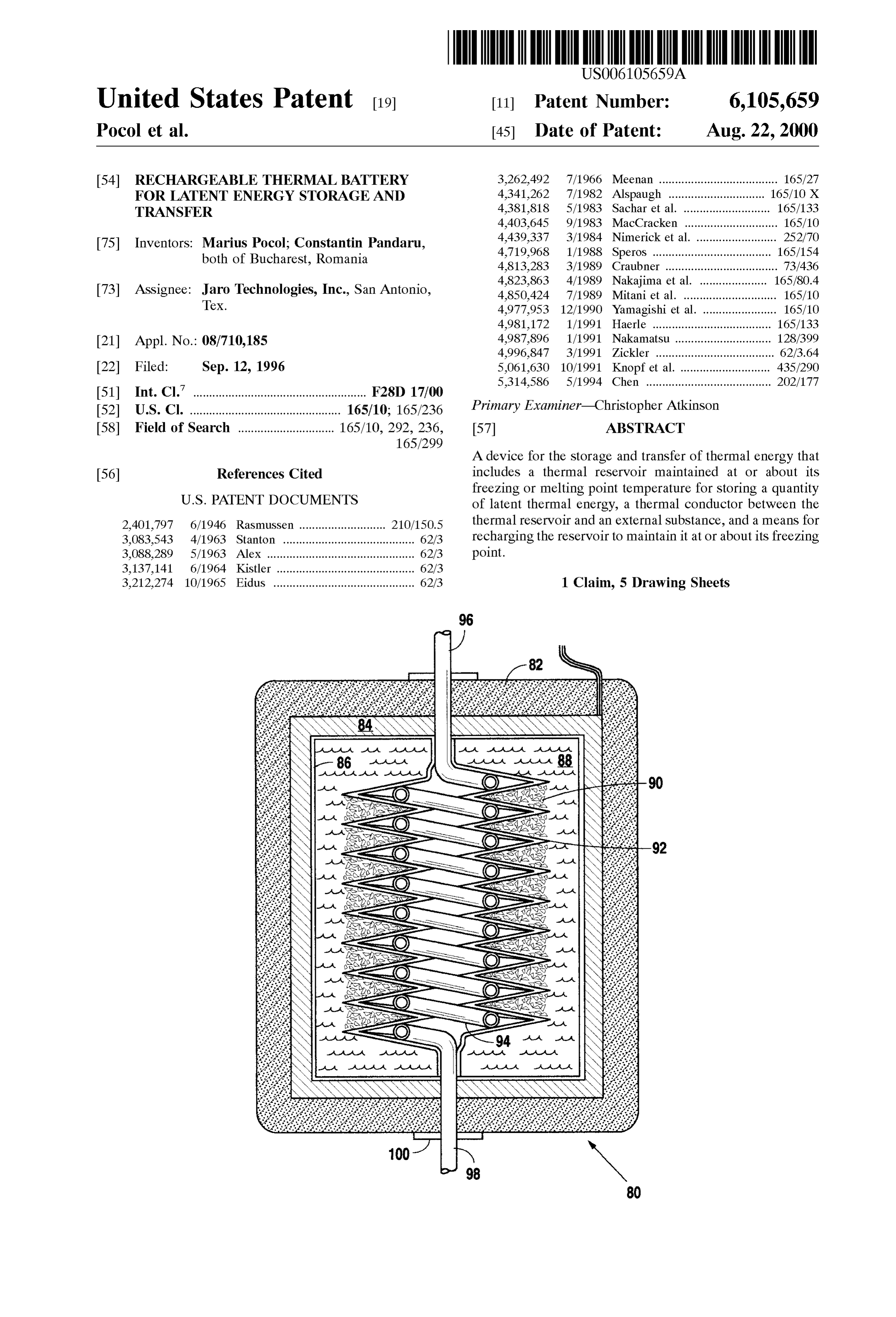
United States Patent (19) 11 Patent Number: 6,105,659 POcol et al. (45) Date of Patent: Aug. 22, 2000 54 RECHARGEABLE THERMAL BATTERY 3.262,492 7/1966 Meenan ..................................... 165/27 FOR LATENT ENERGY STORAGE AND 4,341,262 7/1982 Alspaugh ... 165/10 X TRANSFER 4,381.818 5/1983 Sachar et al. ... 165/133 4,403.645 9/1983 MacCracken .. ... 165/10 (75) Inventors: Marius Pocol; Constantin Pandaru, 4,439,337 3/1984 Nimerick et al. ......................... 252/70 both of Bucharest, Romania 4,719,968 1/1988 Speros ..................................... 165/154 4,813,283 3/1989 Craubner ........ ... 73/436 4,823,863 4/1989 Nakajima et al. 165/80.4 73) ASSignee: Jaro Technologies, Inc., San Antonio, 4,850,424 7/1989 Mitani et al. ....... ... 165/10 TeX. 4,977,953 12/1990 Yamagishi et al. . ... 165/10 4,981,172 1/1991 Haerle ............ ... 165/133
Appl. No.: 08/710,185 4,987,896 1/1991 Nakamatsu . ... 128/399 4,996,847 3/1991 Zickler ........ ... 62/3.64
Filed: Sep. 12, 1996 5,061,630 10/1991 Knopf et al. 435/290 5,314,586 5/1994 Chen ....................................... 202/177
Int. Cl. ............................................... F28D 17/00
U.S. Cl. ............................................... 165/10; 165/236 Primary Examiner-Christopher Atkinson
Field of Search .............................. 165/10, 292, 236, 57 ABSTRACT
A device for the Storage and transfer of thermal energy that
References Cited includes a thermal reservoir maintained at or about its freezing or melting point temperature for Storing a quantity
2,401,797 6/1946 Rasmussen ........................... 210/150.5 thermal reservoir and an external Substance, and a means for 3,083,543 4/1963 Stanton ......................................... 62/3 recharging the reservoir to maintain it at or about its freezing 3,088,289 5/1963 AleX .............................................. 62/3 point.
3,137,141 6/1964 Kistler ........................................... 62/3 3,212.274 10/1965 Eidus ............................................ 62/3 1 Claim, 5 Drawing Sheets
egree
Page 2
Drawing sheet — no readable text.
Page 3
Drawing sheet — no readable text.
Page 4
Drawing sheet — no readable text.
Page 5
Drawing sheet — no readable text.
Page 6
Drawing sheet — no readable text.
Page 7
RECHARGEABLE THERMAL BATTERY PREVENTING FREEZING TOGETHER OF VARIOUS FOR LATENT ENERGY STORAGE AND SURFACES, describes a freeze “releasing agent that con TRANSFER tains at least three water Soluble components, including: (1)
BACKGROUND OF THE INVENTION
a polyhydroxy compound or a monoalkyl ether thereof; (2) an organic non-volatile compound having at least one hydro 1. Field of the Invention philic group, (2) being different than (1); (3) optionally a Salt The present invention relates generally to devices and which functions to lower the freezing point of water; (4) an methods for Storing and transferring thermal energy for organic polymer which functions to increase Viscosity; and cooling and heating processes. The present invention relates (5) water as a carrying fluid.
more specifically to the Structure and composition of a U.S. Pat. No. 4,987,896 issued to Nakamatsu on Jan. 29, device for the Storage and transfer of latent heat energy for 1991, entitled APPARATUS FOR INCREASING THE the purposes of rapidly and controllably cooling or heating ACTIVITY OF THE HUMAN BRAIN, refers to the use of objects and environments. liquids having low freezing temperatures, and gives as 2. Description of the Related Art examples a 50% aqueous Solution of ethylene glycol, pro 15 pylene glycol, agar Solution or the like.
The transfer and Storage of thermal energy has generally been accomplished through the use of mechanical compres U.S. Pat. No. 4,813,283 issued to Craubner on Mar. 21, Sors and the like that convert mechanical energy into thermal 1989, entitled DENSITY MEASURING APPARATUS, energy through the compression and expansion of appropri describes the use of a liquid for improving the thermal ate compounds such as chloro-fluorocarbons. Problems with coupling between a buoyant fluid and a temperature Sensor. these compounds and their effect on the environment, In the case of certain low temperature experiments, the however, have led those in the field to examine alternative coupling fluid is described as having a Sufficiently low compounds for use in mechanical compressor devices and to freezing point, and may comprise methanol, ethanol, look to other means for the Storage and transfer of thermal toluene, isopentene and other Suitable liquids. energy. While Solid State thermal energy devices have been 25 U.S. Pat. No. 3,381,818 issued to Sachar et al. on May 3, known for Some time, their use has generally been limited 1983, entitled POROUS FILM HEAT TRANSFER, because of their inability to either rapidly deliver the thermal describes a composition intended for use as a heat Sink film energy required or to Store that energy over time in a device to be coated on the Surface of an integrated electronic circuit. that can, thereafter, rapidly deliver it in large quantities. One The film is composed of a porous metal, preferably alumi common Solid State thermal energy device known as the U
Peltier element is capable of transferring thermal energy into U.S. Pat. No. 4,981,172 issued to Haerle on Jan. 1, 1991, or Out of an object or environment that it is in contact with, entitled MECHANISM FOR HEAT TRANSFER, describes but unfortunately these operate efficiently only at a relatively a heat transfer device that is coated at least in part with metal slow rate. Such Peltier element devices lend themselves to Shavings, metal wires, or coarse metal powder made of applications where either the gradual transfer of thermal 35 thermally conducted material and then Sintered. Haerle also energy is desired or a device is in place for the Storage of describes initially distributing the metallic powder by thermal energy for later use. Shaking, by introduction over a Sticky liquid, or by electrical There have been a number of attempts in the past to create and/or magnetic effects.
materials, devices, and methods for the rapid cooling or U.S. Pat. No. 4,996,847 issued to Zickler on Mar. 5, 1991, heating of objects or environments. The following patents 40 entitled THERMOELECTRIC BEVERAGE COOLER are representative of these efforts. AND DISPENSER, describes a system that employs a U.S. Pat. No. 4,823,863 issued to Nakajima et al. on Apr. Peltier element in the cooling of a liquid dispensed from a 25, 1989, entitled THERMAL CONDUCTION DEVICE, beverage bottle inserted into the top of the device. This describes the Structure of an interface between a heat gen device employs the Peltier element in conjunction with a erating element, typically an electronic component, and a 45 honeycomb array of beverage passageways to quickly cool heat Sink element. This interface includes a porous layer the liquid.
made of Sintered metallic particles that form a rigid Sponge U.S. Pat. No. 4,719,968 issued to Speros on Jan. 19, 1988, like Structure within which a heat conductive oil is retained. entitled HEAT EXCHANGER, describes a heat exchange U.S. Pat. No. 5,061,630 issued to Knopfet al. on Oct. 29, mass made up of particles of crystalline carbon, copper and 1991, entitled LABORATORY APPARATUS FOR 50 aluminum. The SperoS heat eXchanger is described as taking OPTIONAL TEMPERATURE-CONTROLLED HEATING a cylindrical or planar configuration and may be contained AND COOLING, describes the use of small particles of a within metal conduits or, in the case of Solar radiation, heat conducting Solid Such as graphite or metal powder, or transparent or translucent enclosures.
Spheres of metal or glass, that Serves both to conduct heat U.S. Pat. No. 5,314,586 issued to Chen on May 24, 1994, and to Stabilize vessels that are placed within the particles. 55 entitled PURIFYING AND ENERGY-SAVING WATER The device uses a Peltier element in contact with a metallic FOUNTAIN CAPABLE OF SUPPLYING ICY, WARM core that in turn is in contact with the Small particles. AND HOT DISTILLED WATER, discloses an electronic U.S. Pat. No. 2,401,797 issued to Rasmussen on Jun. 11, chilling device that consists of radiating fins, a Peltier 1946, entitled HEAT EXCHANGER, describes another use element and condensing fins. The patent also describes the of Sintered metal as the medium for a heat eXchanger. In 60 use of a eutectic melting Salt as a thermal medium within Rasmussen, a number of copper tubes pass through the which a coil cooling pipe is positioned.
Sintered, highly porous block of bronze. The Sintering is U.S. Pat. No. 3,088,289 issued to Alex on May 7, 1963, carried out after the tubes are imbedded in the bronze entitled WATER COOLER, describes a Peltier element powder So that bonding is accomplished between the Sin positioned between an array of radiating fins or channels, tered metal and the copper tubes. 65 and an interior cooling plate that Surrounds the liquid being U.S. Pat. No. 4,439,337 issued to Nimericket al. on Mar. cooled. Insulation around the entire Structure prevents heat 27, 1984, entitled COMPOSITION AND METHOD FOR loSS after cooling.
Page 8
The above patents describe Systems that in general fail as It is therefore an object of the present invention to provide Solid State thermal energy mechanisms capable of large Scale a device for the Storage of thermal energy. useful application. The use of Solid State cooling and heating It is a further object of the present invention to provide a devices has generally been limited to very Small applications thermal energy Storage and transfer device capable of heat where high rates of energy transfer are not required. Most 5 ing or cooling objects and environments and operable at a attempts in the past to create thermal Storage devices of constant temperature or over a narrow temperature range. Significant size (from the Standpoint of the quantity of heat It is a further object of the present invention to provide a energy they can retain) and with Substantial transfer rates thermal (from the standpoint of how fast they can absorb or deliver Sink for energy large
Storage device capable of acting as a thermal quantities of heat present in the environment thermal energy), have been limited to mechanical devices Surrounding the device Such that the device may serve to Such as compressors that are Subject to all the disadvantages cool the environment.
asSociated with any Such non-Solid State configurations.
SUMMARY OF THE INVENTION
It is a further object of the present invention to provide a thermal energy Storage device capable of acting as a thermal
It would be desirable, therefore, to have devices and 15 reservoir for retaining large quantities of heat and control methods for the rapid cooling or heating of objects or spatial lably releasing Such heat into the environment Surrounding environments that incorporate no moving mechanical parts the device.
and take up significantly less Space than the well known It is a further object of the present invention to provide a compressor based thermal pump Systems. It would be desir thermal Storage device, and structures associated with the able if these devices and methods could operate at constant device, capable of drawing off large quantities of heat from temperatures and could be made inexpensively of materials a fluid or gas that is conducted through the device Such that not toxic to the environment or to the user. It would be the fluid or gas is cooled once it is released from the device. desirable if these devices could be of Such a size as to be easily utilized in a large variety of thermal heating and thermal It is a further object of the present invention to provide a cooling applications. Storage device, and structures associated with the 25 device, capable of releasing large quantities of heat into a
One primary element of the cooling devices and methods fluid or gas that is conducted through the device Such that the of the present invention is the preferred use of gels, Solids, fluid or gas is heated once it is released from the device. and aqueous Solutions capable of being thermally charged So It is a further object of the present invention to provide a as to absorb and Store large quantities of heat. Secondary thermal features of the cooling devices and methods of the present insulatedStorage device that is Small in Size and is thus easily So as to maintain over time the thermal reservoir invention include the Structures and configurations appro characteristics of the device.
priate for utilizing the thermal Storage compounds in the process of rapidly cooling or heating Solid objects or fluid or It is a further object of the present invention to provide a gas Streams brought into contact with the devices. thermal storage and transfer device that operates on a highly The basic concept and one goal of the present invention 35 reversible process that enables the device to be repeatedly is to provide a very large thermal reservoir in a very Small recharged without significant degradation. Spatial Volume. This is accomplished by the use of Specific It is a further object of the present invention to provide gels, Solids, and aqueous Solutions described herein and by devices and methods that are uSable in conjunction with a the use of thermal transfer Structures that take advantage of variety of thermal Storage compounds that can be selectively the thermal characteristics of these gels, Solids, and Solu 40 chosen in accordance with the requirements of a particular tions. The benefits of maintaining a very Small spatial application's temperature range and heat flow requirements. volume in the devices of the present invention lie in the It is a further object of the present invention to provide a ability to easily insulate Such volumes and prevent the loSS thermal Storage device that incorporates materials that are of a thermal charge once it is in place. non-hazardous to the user and environment, Specifically Various applications of the present invention are 45 through the non-use of Structures that increase the transfer anticipated, including the cooling of water and other fluids Surface area, including the use of chloro-fluorocarbons. for drinking purposes as well as the cooling of fluids and In fulfillment of these and other objectives, the present gases for the purposes of refrigeration and air-conditioning. invention provides a thermal Storage and delivery device and It is anticipated that this non-chloro-fluorocarbon based method that approaches the problem of transferring heat refrigerant System would have application in air condition 50 energy to and from objects and environments by Selecting ing units for vehicles and in larger enclosures. It is also Substances with known latent heat values most appropriate anticipated that the Structures described within the present for the Situation, and encasing these Selected Substances in invention could be implemented in portable rechargeable Structural enclosures optimized for the transfer of heat block configurations that may be inserted into containers of energy into or out of the object or environment to be cooled fluid or gas much along the lines of inserting large ice blockS 55 or heated. The structures of the present invention involve the or the like into Such containers. use of membrane walls between the Substances acting as In general, the Structures of the present invention are thermal reservoirs and the object or environment to be reversible both in physical orientation and in use. A fluid or cooled or heated. The transfer of heat energy through these gas may be passed through a device defined by the present membrane walls is facilitated by the use of structures that invention or an inversely configured device could be 60 increase the transfer Surface area, including the use of immersed within the fluid or gas or placed in contact with a metallic powders that may adhere to or be attractively Solid object. Likewise, the materials and compositions of the positioned on the membrane walls and yet Still be immersed present invention lend themselves to utilization both as in the Substance acting as the thermal reservoir. The Selected reservoirs for drawing large quantities of heat from a fluid, Substances used as the thermal reservoir are contained gas, or Solid brought in contact with the device, or in 65 within enclosures that permit the use of Peltier electrical delivering large quantities of heat to the fluid, gas, or Solid, devices or other thermal transfer mechanisms for the once Such heat has been Stored. recharge and/or maintenance of the thermal reservoir.
Page 9
S 6
Finally, the Structures of the present invention are designed of appropriate Substances whose freezing point/melting to be Sufficiently compact So that insulative envelopes, point temperatures and latent heat characteristics fit the where they are required, are highly efficient because of their requirements of the Situation, but also the Selection of relatively low external Surface area for heat transfer to occur. Structural heat conductive elements that facilitate the par Other objects of the present invention will become clear ticular flow of heat required. Unlike the chemical reactions from a consideration of the detailed description that follows carried out in most electrical batteries, the processes carried and the appended drawings and claims. out in the thermal batteries of the present invention are, for all practical purposes, completely reversible. Thus, depend
BRIEF DESCRIPTION OF THE DRAWING ing on the application, the recharge cycle of the present invention is repeatable for an indefinite period of time.
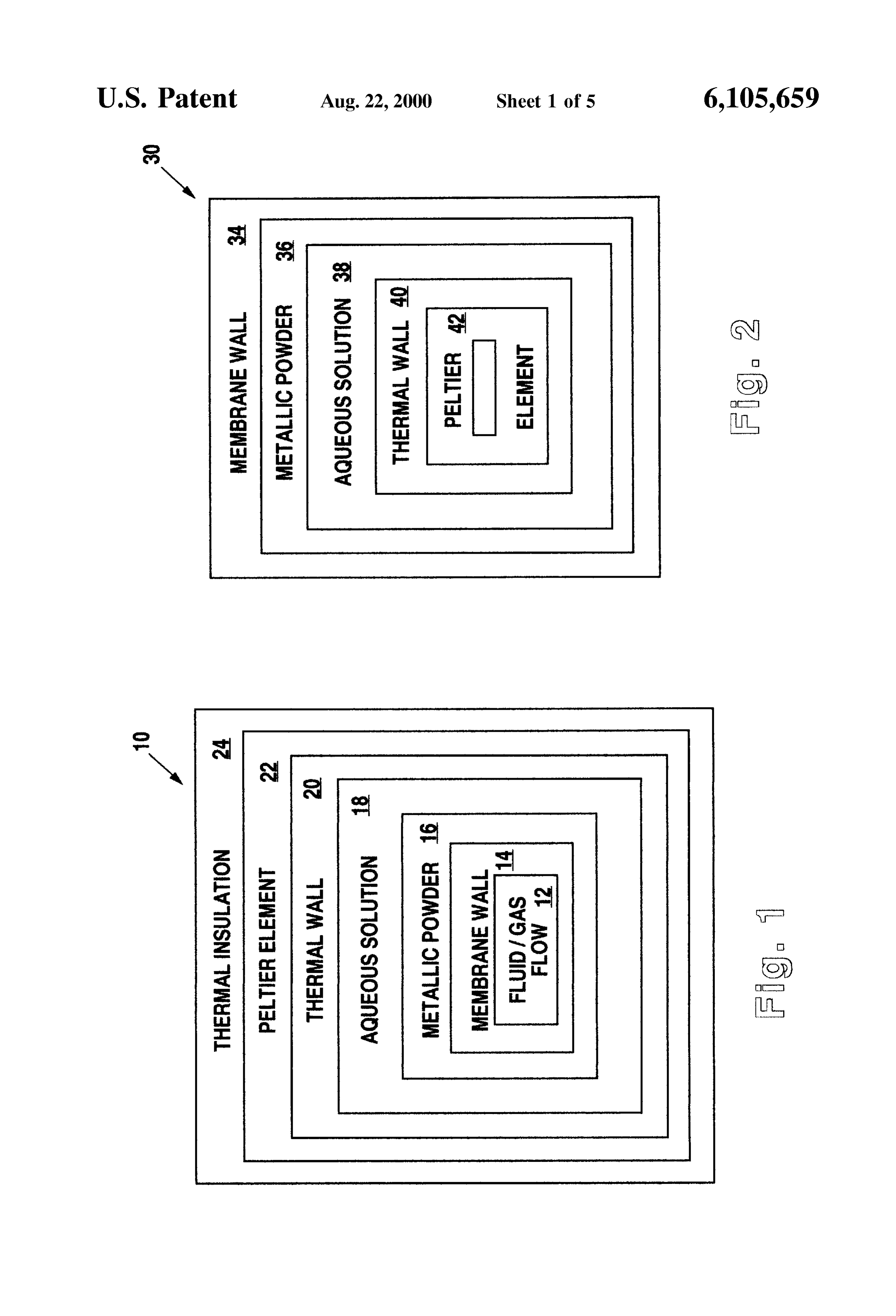
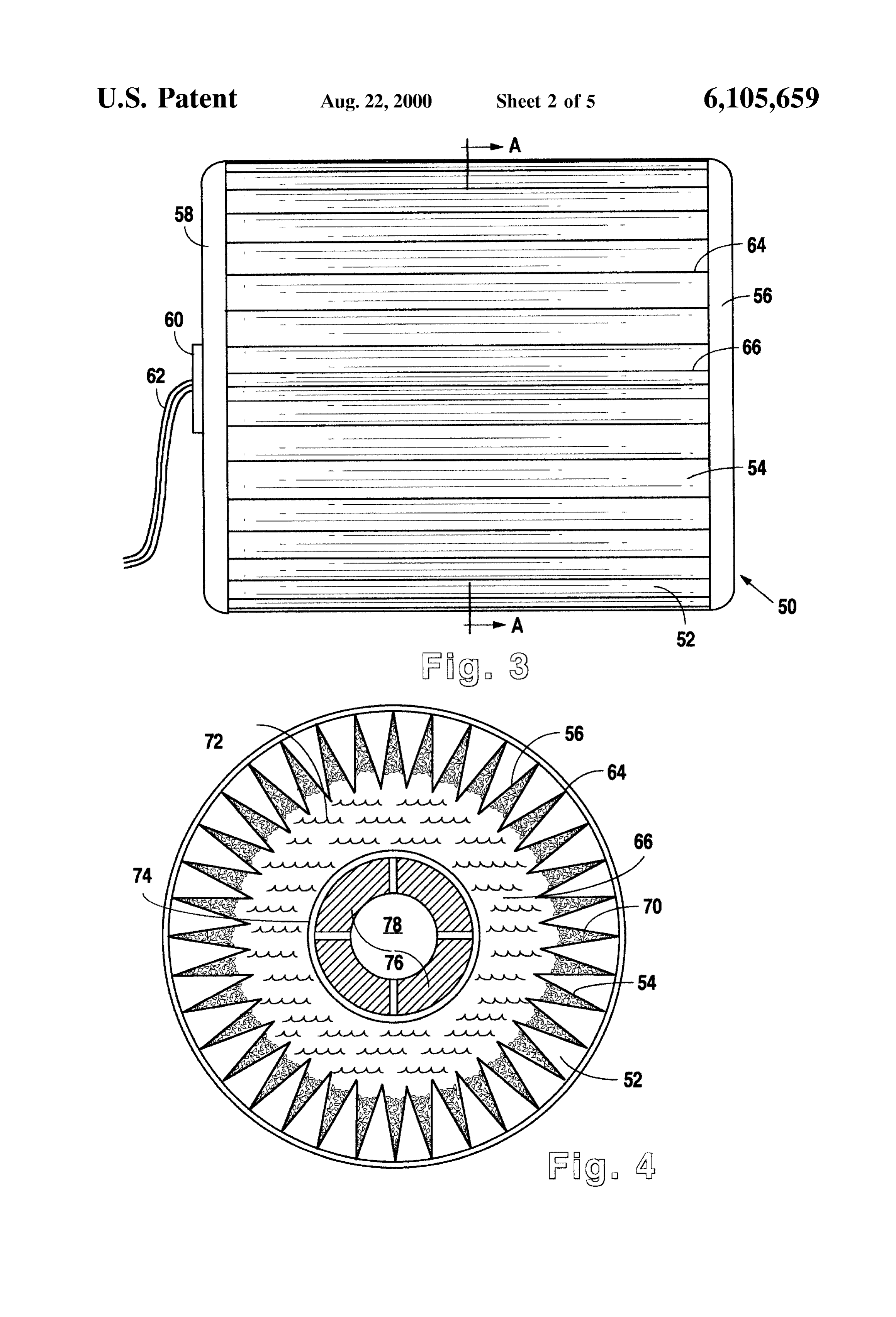
FIG. 1 is a Schematic block diagram showing the primary In FIG. 1, thermal battery (10) is comprised of a sequence Structural elements of a device following the present inven of enclosed elements that concentrically Surround the flow tion as may be used to heat or cool a flow Stream of a fluid of the fluid or gas that is to be cooled or heated. Fluid/gas or gas. flow (12) would, in the typical situation, occur through a FIG. 2 is a Schematic block diagram showing the primary 15 conduit pipe, tube, or the like. Membrane wall (14) is Structural elements of a device following the present inven provided to surround the fluid/gas flow either directly in the tion as may be used for immersion into a liquid or gas form of a pipe or conduit, or indirectly by thermal contact environment that is to be heated or cooled or be brought into with the pipe or conduit. In the preferred embodiment, contact with a Solid to be heated or cooled. membrane wall (14) is in direct contact with fluid/gas flow FIG. 3 is a side view of the structure of a first preferred (12).
embodiment of a thermal Storage device of the present Energy transfer in the device of the present invention is invention. carried out through Solid walls positioned between the FIG. 4 is a cross-sectional view of the device shown in thermal reservoir and the Substance or environment to be FIG. 3 taken along section line A. heated or cooled. These Solid walls will comprise one or a 25 combination of three basic wall structures. These three basic
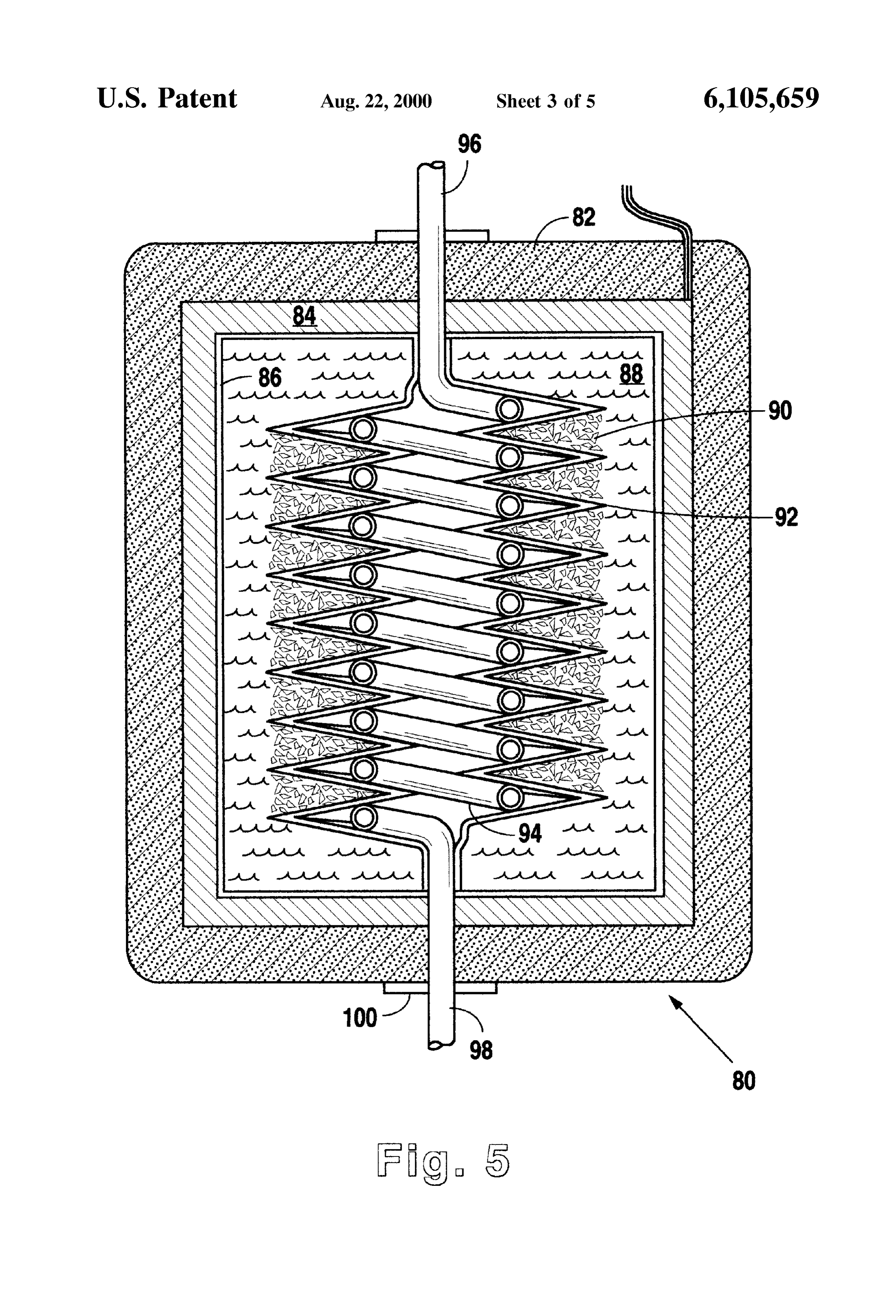
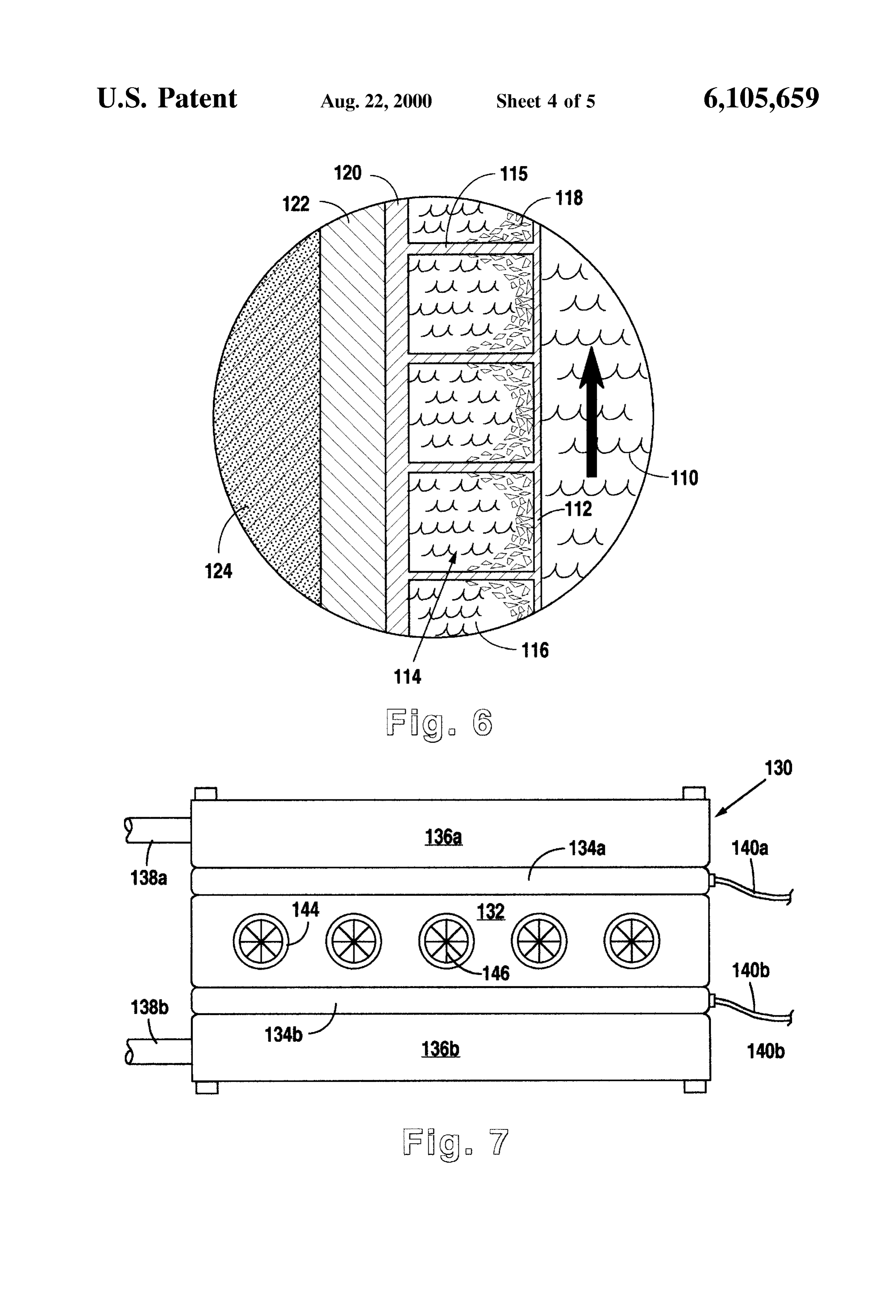
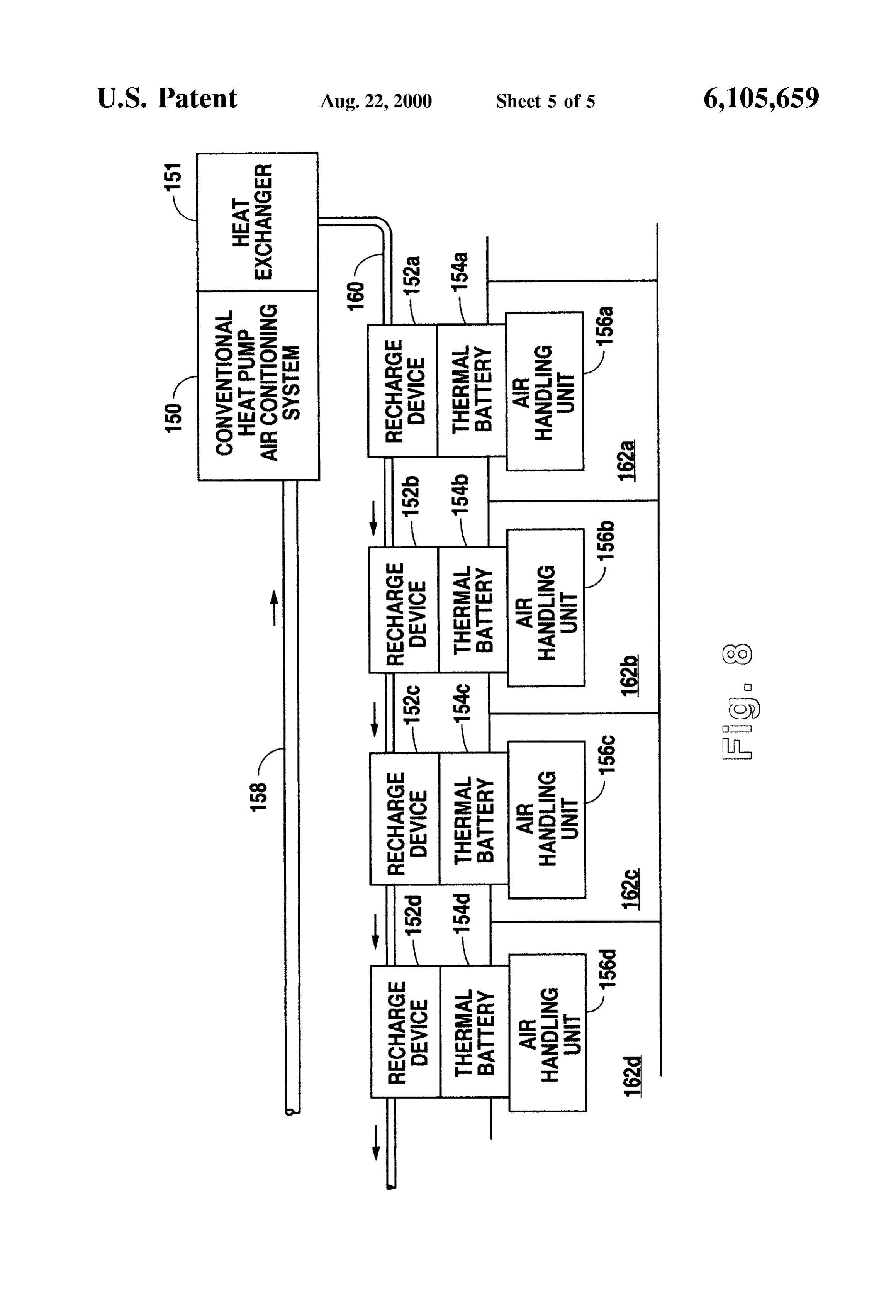
FIG. 5 is a cross-sectional view of a second preferred Structures include cellular walls, walls with increased Sur embodiment of the present invention implementing the face areas for a given Volume, and magnetic walls. Cellular generic structure described in FIG. 1. wall structures are described in more detail below with FIG. 6 is a detailed cross-sectional view of a container respect to FIG. 6 and generally contain Substances or mate wall Structure implementing the principles of the present rials that include graphite powders, metallic powders (Such invention. as Silver, copper, aluminum, or their alloys), or combinations FIG. 7 is a schematic side view of one implementation of of graphite and metallic powderS or Substances containing the present invention for use in conjunction with an auto them. Walls with increased Surface area incorporate various motive air conditioning System. geometries Such as Wings, corrugations, teeth, indents, FIG. 8 is a Schematic block diagram showing implemen 35 helicoils, and So on that may be chosen according to the tation of the present invention in conjunction with a con requirements of the Specific application. Magnetic walls ventional air conditioning System where multiple air han contain at least two layers, one of which may be magnetic dling units are in place. and to which are attached magnetic powders and/or the powderS described above. In any event, energy transfer is
DETAILED DESCRIPTION OF THE
40 accomplished through these Solid walls between the thermal
PREFERRED EMBODIMENT Storage material and the outside object or environment. A Reference is made first to FIGS. 1 and 2 for a detailed rapid transfer of energy is accomplished by the increased description of the primary elements of the present invention Surface area created by the above-described mechanisms. that form the basis of the Structural configuration and the In many applications of the present invention, it is pref methods involved in effecting the present invention. 45 erable to incorporate metallic powder (16) in conjunction FIG. 1 is a Schematic block diagram showing the elements with membrane wall (14) so as to facilitate the heat transfer of a device of the present invention appropriate for use in between membrane wall (14) and aqueous solution (18). heating or cooling a fluid or gas flow as might be carried Metallic powder (16) serves to increase the surface area through a conduit or pipe. It is appropriate to make the through which heat may flow between aqueous solution (18) analogy between the device of the present invention and an 50 and membrane wall (14). Other mechanisms for increasing electrical battery insofar as the principles involved are the interface Surface area may also be employed. Various analogous both in function and in the Structures that these structural folds in the membrane wall itself may provide a functions dictate. Whereas an electrical battery provides a Sufficient heat transfer conduit in Some situations, eliminat reservoir for generating the flow of electrical current in a ing the need for the particles shown in FIG. 1. conductor, the thermal battery of the present invention 55 In certain applications, it is anticipated that metallic provides a mechanism and a reservoir for causing a thermal powder (16), in addition to having optimal thermal flow within appropriate Structural elements. Whereas an characteristics, would be ferromagnetic in nature So as to electrical battery typically includes compounds that carry readily deposit itself on a ferromagnetic metal based mem out a chemical reaction that results in the establishment of an brane wall (14). It is not necessary that metallic powder (16) electrical potential difference, the present invention utilizes 60 be rigidly attached, as through a Sintering process or the like, Selected Substances whose latent heat characteristics are to membrane wall (14). This is especially true if metallic appropriate for providing a given amount of heat flow over powder (16) is made to be magnetic in character and is a specified period of time. AS with electrical batteries, the Simply permitted to attach itself to the Surface of membrane conductors that are attached to the device at least partially wall (14) in a distribution appropriate for the flow of determine the rate of the flow of energy from the device as 65 aqueous Solution (18) therethrough.
well as the ability to recharge the device. Thus, the prin Aqueous solution (18), the selection of which is described ciples of the present invention involve not only the Selection in more detail below, is chosen So as to have characteristics
Page 10
appropriate for the temperature, the thermal Storage, and the described in more detail with respect to FIG. 8. In this thermal flow requirements of a particular application. In respect, it is anticipated that the present invention could be general, the present invention is utilized where large quan utilized as both the primary component in a new installation tities of heat flow are required over Short periods of time at for a heating or cooling System, or as a retrofit element to relatively constant temperatures, utilizing Small Volumes of upgrade or improve the efficiency of an existing heating or a thermal reservoir. Thus, aqueous Solution (18) is in the cooling System.
preferred embodiment typically an organic or inorganic FIG. 2 describes a device structure that is essentially the Solution, Such as those Substances identified in the tables inverse of that shown in FIG. 1. Whereas the device in FIG. below, that is capable of Storing large quantities of heat 1 would be utilized in association with the cooling or heating energy within the crystalline and molecular Structures of the of fluid or gas in a stream through the device, FIG. 2 Substance over a constant or relatively narrow temperature describes the construction of a device appropriate for use range associated with the melting point (freezing point) of where the device is to be immersed in or otherwise brought the Substance.
AS is well known in the art, latent heat energy is that into contact with the object or environment to be heated or amount of energy that may flow in or out of a Substance as 15 cooled. In this case, thermal battery (30) is comprised of the temperature of the Substance passes through the melting membrane wall (34) Surrounding the device and Serving as the primary conduit of heat flow in or out of the device.
(freezing) point of the Substance. As this latent heat flow Metallic powder (36) is, as described above, distributed on occurs, the temperature of the Substance remains relatively membrane wall (34) in order to facilitate the flow of heat constant at the melting (freezing) point. Normally, as heat energy flows in or out of a Substance it effects a temperature between aqueous solution (38) and membrane wall (34). change in the Substance. At the particular melting or freezing Thermal wall (40) provides the conduit between aqueous point of the Substance, a flow of heat energy in or out of the recharge (38) solution and Peltier element (42) which again serves to the device by either extracting heat from aqueous
Substance instead carries out a phase change rather than a Solution (38) or directing heat back into acqueous Solution temperature change. Different Substances have greater or lesser latent heat energy values that reflect the amount of 25 (38).
heat that may flow in or Out of a Substance before tempera It is anticipated that the device structure shown in FIG. 1 ture changes in the Substance are once again exhibited. would function in a manner Similar to Standard refrigeration Aqueous Solution (18) is therefore Selected according to the or heating Systems where a fluid or gas is conducted through freezing temperature and the latent heat energy values the device and heated or cooled for Subsequent use after required for a particular Substance and the appropriateneSS passing out of the device. FIG. 2, on the other hand, would of these parameters for the requirements of the application function more in the nature of a “block of ice' or a "hot involved. rock” that is immersed in the fluid or gas to be heated or Surrounding aqueous solution (18) is thermal wall (20) cooled or is brought into thermal contact with the solid to be which functions as conduit for the recharge of aqueous heated or cooled. In either case, the principles of heat flow are the same, it is simply the orientation of Structural solution (18) and not for the conduction of heat in or out of 35 elements the object to be cooled or heated. In a preferred embodiment, that changes in order to direct that heat flow into thermal wall (20) is a conduit between aqueous solution (18) or Out of the Substance of concern. and Peltier element (22). Peltier element (22) provides a Reference is now made to FIGS. 3 and 4 for an example non-mechanical, Solid State mechanism for recharging aque of a first preferred embodiment of the present invention ous Solution (18) by either directing heat energy into the 40 showing application of the Structures generally referred to in Solution to Store for later use or extracting heat energy from FIG. 2. Thermal battery (50) disclosed in FIG. 3 is a the Solution to provide a thermal Sink for the cooling of an cylindrical Structure comprised primarily of metallic com object or environment. Peltier element (22) is, in conjunc ponents that encase a Selected Substance used as a thermal tion with the rest of thermal battery (10), surrounded by reservoir. Thermal battery (50) is made up of a cylindrical thermal insulation (24) to reduce the environmental effects 45 shell (52) which is itself made up of an array of radiating of heat flow in or out of the overall system. walls (54). Cylindrical shell (52) is capped on either end by Although most of the examples presented herein of the end cap (56) and end cap (58). Radiating walls (54) meet at implementation of the present invention use a Peltier ele exterior edges (64) and again at interior edges (66). The ment as the mechanism for recharging the thermal reservoir, structure of these radiating walls (54) is better disclosed and it is anticipated that any of a number of different mecha 50 described in the cross-section view shown in FIG. 4. nisms for thermally recharging the reservoir could be uti The structure of thermal battery (50) disclosed in FIG. 3 lized. AS one object of the present invention is to provide a is Such as would be appropriate for immersion of the device Solid State device that is not Subject to the maintenance into a liquid or gas that is to be cooled or heated. Radiating requirements often found in conjunction with compressor walls (54) are designed to facilitate the transfer of heat to the based units, it is anticipated that a number of other non 55 Substance to be cooled or heated and Serve as the membrane compressor based Systems could be utilized in place of the walls described with reference to FIG. 2. The walls (54) are Peltier element. For example, use of the present invention in preferably constructed of materials that are both thermally Some environments that operate at high altitude or under conductive and Structurally Strong. Metals. Such as aluminum water where external conditions provide adequate thermal or copper provide both conductivity and Strength under most cooling capabilities, external air or water might be con 60 conditions. In many instances, it is desirable that walls (54) ducted to the thermal battery structure of the present inven be configured to adapt to changes in ambient pressure. This tion for the purpose of gradually recharging the battery adaptability could be provided by selection of flexible during and after use. Likewise, it is anticipated that in Some materials or by the design of flexible enclosures as would Situations conventional cooling and heating units could be allow for the expansion and contraction of the compound utilized to recharge the thermal batteries of the present 65 acting as the thermal reservoir. The flow of a fluid or gas to invention at a rate that allows for the most efficient operation be heated around thermal battery (50) could be forced by of the conventional units. One example of this latter case is external flow mechanisms or could simply be the natural
Page 11
flow resulting from the temperature differentials developed physical transport of the fluid or gas through the System. The as a result of the fluid or gas contact with thermal battery structure of wall (92) shown in FIG. 5 is therefore provided (50). Recharge of thermal battery (50) is accomplished as illustrative only and as could vary Significantly in appear through electrical connection (62) that connects to the ance depending upon the Specific application. Peltier elements (not shown in FIG. 3) interior to thermal It is anticipated, for example, that the flow of fluid or gas battery (50). Electrical conductors (62) are sealed against the through the System of the present could be carried out external fluid or gas by way of end cap seal (60). through a Straight conduit with no bends or coil-like con FIG. 4 shows, in croSS-Sectional detail taken along line A figurations as are shown in FIG. 5. While this would in FIG. 3, the interior of thermal battery (50). Radiating facilitate the flow of the substance through the device, it walls (54) are shown as they meet at external edges (64) and would reduce the amount of time that the fluid or gas spends internal edges (66) and as they are positioned with respect to in contact with the thermal reservoir of the device. In many the perimeter of end cap (56). Positioned and distributed instances, the amount of time that the fluid or gas is in within the interior angles of radiating walls (54) is metallic contact with the thermal reservoir is less critical than the powder (70). Allowed to distribute itself on these walls as by 15 need for rapid flow through the device. In Such a case, the magnetic means described above, metallic powder (70) modifications of the structure shown in FIG. 5 would be is permeated by aqueous Solution (72) and in conjunction appropriate.
with radiating walls (54) provides an increased Surface area Reference is now made to FIG. 6 for a description of a of contact between acqueous Solution (72) and the environ third preferred embodiment of the present invention that has ment external to the device. Aqueous Solution (72) is main general applicability to both the structure shown in FIG. 1 tained and enclosed on the interior of thermal battery (50) and that shown in FIG. 2. FIG. 6 discloses in cross-section both by end caps (56) and (58) and radiating walls (54). the Structure of a thermal reservoir wall Such as might be Aqueous solution (72) surrounds thermal wall (74) which used for either a container within which a Solid, liquid, or Serves to conduct heat from aqueous Solution (72) in and/or gas is enclosed, or a block that may be immersed in a fluid out of Peltier elements (76). Peltier elements (76) are or gas or brought into contact with a Solid. positioned around a central core (78) that may either be 25 The wall structure shown in FIG. 6 is positioned adjacent closed or open in the preferred embodiment depending upon to flow (110) of a fluid or gas to be heated or cooled. the Specific requirements of the Structure of Peltier elements Membrane wall (112) serves as the interface for the flow of (76). heat in or out of flow (110). The wall structure of FIG. 6 is Reference is now made to FIG. 5 for a detailed description made up of individual cells (114) that are bounded by of an implementation of the device of the present invention membrane wall (112) on one side and a plurality of cellular in the manner shown in FIG. 1. FIG. 5 shows an appropriate walls (115) on the inside. Cellular walls (115) connect to Structure for utilizing the device of the present invention to thermal wall (120). Each cell (114) contains aqueous solu heat or cool a fluid or gas Stream as it passes through the tion (116) and metallic particles (118). Metallic particles device. With the objectives of the present invention in mind, 35 (118) are either magnetized or are ferromagnetic So as to be especially those of Small size and large thermal Storage attracted to and distribute themselves along membrane wall capabilities, thermal battery (80) is structured to conduct a (112). Aqueous solution (116) contained within each cell fluid or gas through the device for the purposes of heating or (114) may be recharged through structural wall (120) by way cooling it. Thermal battery (80) is comprised of external of Peltier element (122). Peltier element (122) is insulated insulating shell (82) that surrounds Peltier elements (84). 40 from the external environment by way of insulating layer Appropriate electrical connectors for the function of Peltier (124).
elements (84) pass through insulative shell (82). AS indicated above, the wall structure shown in FIG. 6 Aqueous solution (88) is contained within thermal wall could be utilized as the Shell wall of a container that encloses (86) that is in thermal contact with Peltier element (84) and be a solid, liquid, or gas (110). In this case, cells (114) would Serves as a mechanism for transferring heat in and out of 45 directed to the interior of the container whereas Peltier aqueous Solution (88) So as to maintain and/or recharge element (122) and insulative layer (124) would be on the thermal battery (80). Aqueous solution (88) surrounds a structure exterior of the container. On the other hand, the wall coiled Structure configured to permit an efficient flow of heat shown in FIG. 6 could be utilized in the form of a in or out of the fluid or gas to be heated or cooled. Membrane solid block or plate with cells (114) positioned on the wall structures (92) are positioned within aqueous Solution 50 exterior surface of the device and Peltier element (122) positioned within the center of the device not unlike the (88) and have distributed over their surface metallic particles structure (90) in a manner that increases the Surface area of contact shown in FIGS. 3 and 4. between aqueous solution (88) and membrane wall (92). Every embodiment of the present invention incorporates Interior to membrane wall (92) is conduit (94) which carries the use of an aqueous Solution or a gel/Solid Substance whose the fluid or gas to be heated or cooled. Inlet (96) and outlet 55 latent heat and freezing point temperature characteristics are (98) are the connection points for introducing and extracting appropriate to provide the thermal reservoir necessary in any the liquid or gas flow through thermal battery (80). Cap seals given Situation. Most frequently, the Substances involved (100) complete the insulative characteristics of insulative would include a selection of the following: shell (82) for thermal battery (80). (a) Aqueous inorganic Solutions with freezing points It is anticipated that wall structure (92) shown in FIG. 5 60 between -60° C. and -10° C. These would include is but one of a large number of differing examples of wall inorganic Salt Solutions Such as aqueous Solutions of structures generally referenced by the “membrane wall' potassium iodide, Sodium iodide, and potassium car described above in FIG. 1. Again, this membrane wall bonate.
structure could be the conduit itself that encloses the flow of (b) Aqueous organic Solutions with freezing points fluid or gas through the System. Certain circumstances, 65 between -60° C. and -100° C. These could include however, may dictate one or more Structural layers of a aqueous Solutions of the primary alcohols, Secondary “membrane wall be in place So as to permit the easy alcohols, tertiary alcohols, phenols, aldehydes, ketones,
Page 12
acids, esters, ethers, any combination of the previous aqueous Solutions, and any other Substances which TABLE 2 contain as their base elements these Solutions or com binations of them. CRYSTALLIZING TEMPERATURES FOR AOUEOUSETILIC
ALCOHOL AND GLYCERINE AOUEOUS SOLUTIONS
(c) Aqueous Solutions of Simple and polynuclear complex % WEIGHT 5 1O 2O 40 combinations. ALCOHOL (C.) -1.95 -4.20 -10.7 -30.8 (d) Any other combination of the substances described GLYCERINE (C) -0.45 -1 -2.5 -17.2 above in (a), (b), and (c), or any Substances based on these Substances and any combination of them. 1O
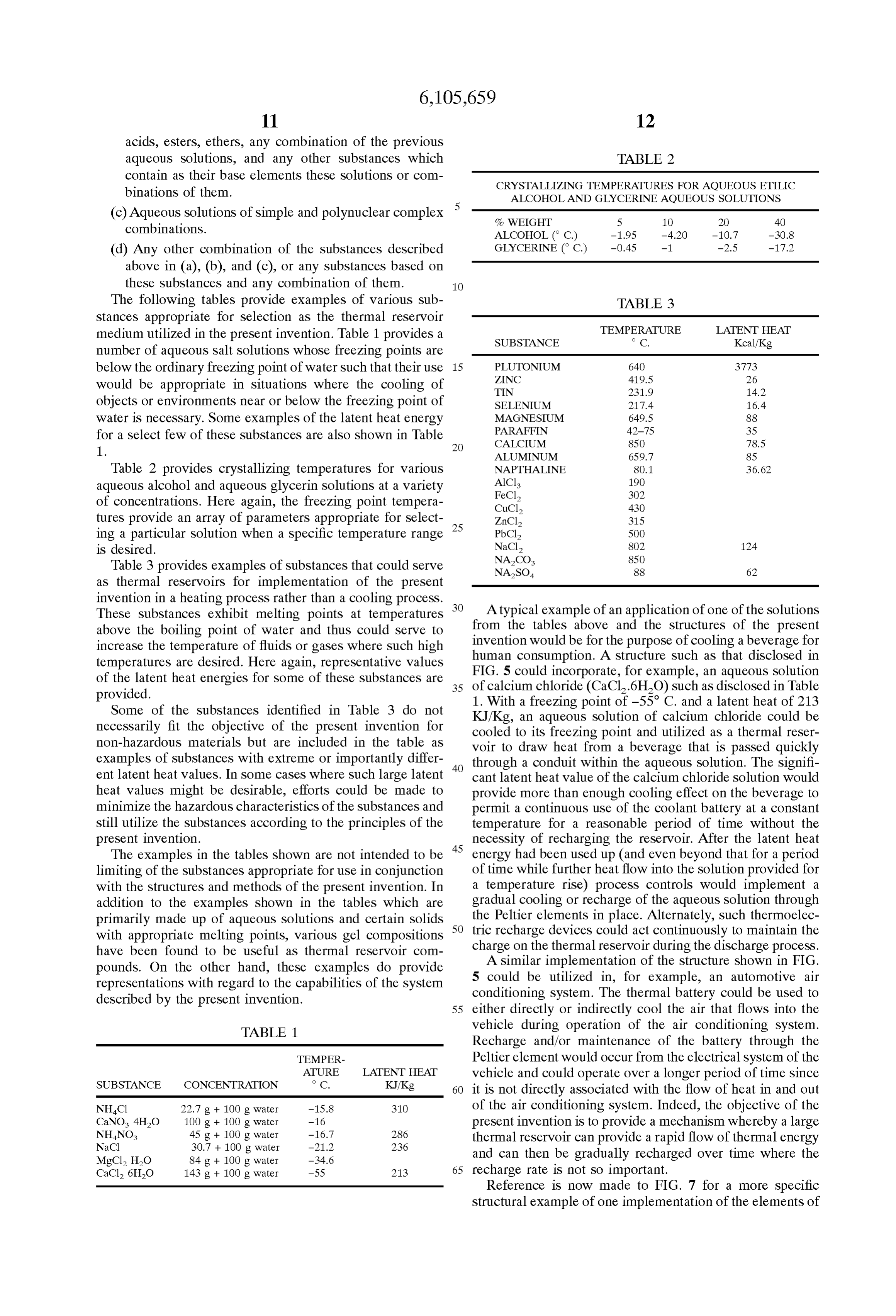
The following tables provide examples of various Sub TABLE 3 stances appropriate for Selection as the thermal reservoir
TEMPERATURE LATENT HEAT
medium utilized in the present invention. Table 1 provides a SUBSTANCE o C. Kcal/Kg number of aqueous Salt Solutions whose freezing points are below the ordinary freezing point of water Such that their use 15 PLUTONIUM
ZINC
would be appropriate in Situations where the cooling of TIN 231.9 14.2 objects or environments near or below the freezing point of SELENIUM 217.4 16.4 water is necessary. Some examples of the latent heat energy MAGNESIUM 649.5 88 for a select few of these Substances are also shown in Table PARAFFIN 42-75 35
1. ALUMINUM 659.7 85 Table 2 provides crystallizing temperatures for various NAPTHALINE 80.1 36.62 aqueous alcohol and aqueous glycerin Solutions at a variety AlCl
FeCl,
of concentrations. Here again, the freezing point tempera CuCl2 430 tures provide an array of parameters appropriate for Select 25 ZnCl2 315 ing a particular Solution when a specific temperature range PbCl, 500 is desired. NaCl, 8O2 124
Table 3 provides examples of substances that could serve NASO 88 62 as thermal reservoirs for implementation of the present invention in a heating process rather than a cooling process.
These Substances exhibit melting points at temperatures A typical example of an application of one of the Solutions above the boiling point of water and thus could serve to from the tables above and the structures of the present increase the temperature of fluids or gases where Such high invention would be for the purpose of cooling a beverage for temperatures are desired. Here again, representative values human FIG. 5 consumption. A structure Such as that disclosed in could incorporate, for example, an aqueous Solution of the latent heat energies for Some of these Substances are 35 of calcium chloride (CaCl.6HO) such as disclosed in Table provided. 1. With a freezing point of -55 C. and a latent heat of 213 Some of the Substances identified in Table 3 do not necessarily fit the objective of the present invention for cooled KJ/Kg, an aqueous Solution of calcium chloride could be non-hazardous materials but are included in the table as to its freezing point and utilized as a thermal reser voir to draw heat from a beverage that is passed quickly examples of Substances with extreme or importantly differ 40 through a conduit within the aqueous Solution. The Signifi ent latent heat values. In Some cases where Such large latent cant latent heat value of the calcium chloride Solution would heat values might be desirable, efforts could be made to provide more than enough cooling effect on the beverage to minimize the hazardous characteristics of the Substances and permit a continuous use of the coolant battery at a constant Still utilize the Substances according to the principles of the temperature for a reasonable period of time without the present invention. necessity of recharging the reservoir. After the latent heat The examples in the tables shown are not intended to be 45 energy had been used up (and even beyond that for a period limiting of the Substances appropriate for use in conjunction of time while further heat flow into the solution provided for with the structures and methods of the present invention. In a temperature rise) process controls would implement a addition to the examples shown in the tables which are gradual cooling or recharge of the aqueous Solution through primarily made up of aqueous Solutions and certain Solids 50 the Peltier elements in place. Alternately, Such thermoelec with appropriate melting points, various gel compositions tric recharge devices could act continuously to maintain the have been found to be useful as thermal reservoir com charge on the thermal reservoir during the discharge process. pounds. On the other hand, these examples do provide A similar implementation of the structure shown in FIG. representations with regard to the capabilities of the System 5 could be utilized in, for example, an automotive air described by the present invention. conditioning System. The thermal battery could be used to 55 either directly or indirectly cool the air that flows into the
TABLE 1. vehicle during operation of the air conditioning System.
Recharge and/or maintenance of the battery through the
TEMPER Peltier element would occur from the electrical system of the
SUBSTANCE CONCENTRATION
ATURE
LATENT HEAT
vehicle and could operate over a longer period of time Since 60 it is not directly associated with the flow of heat in and out
NHCI 22.7 g + 100 g water -15.8 310 of the air conditioning System. Indeed, the objective of the CaNO. 4H2O 100 g + 100 g water -16 present invention is to provide a mechanism whereby a large NHNO 45 g + 100 g water -16.7 286 thermal reservoir can provide a rapid flow of thermal energy
MgCl, HO 84 g + 100 g water -34.6 and can then be gradually recharged over time where the CaCl, 6HO 143 g + 100 g water -55 213 65 recharge rate is not So important. Reference is now made to FIG. 7 for a more specific
Structural example of one implementation of the elements of
Page 13
the present invention. FIG. 7 discloses a simple automotive (154d). In this manner, the high pressure freon lines nor air conditioning unit (130) Suitable for operation and instal mally associated with conventional air conditioning and heat lation in most Small automobiles and truckS. Air condition pump Systems are restricted to a Single location apart from ing unit (130) is comprised of sandwiched layers of the each of the individual room units. A controllable, efficient elements of the present invention. These layers include flow of this liquid in conduits (160) and in return conduit thermal reservoir (132), Peltier elements (134a) and (134b) (158) could maintain each of the recharge device (152a) and heat dissipation plates (136a) and (136b). The function through (152d) in a state sufficient for the continuous of the present invention is carried out through thermal maintenance of each of thermal batteries (154a) through reservoir (132), which in the embodiment shown in FIG. 7 (154d), regardless of the demands placed on any individual preferably uses a gel compound as the material for the thermal battery.
thermal reservoir. In thermal contact with thermal reservoir The benefits of utilizing individual thermal batteries (132), Peltier elements (134a) and (134b) serve to recharge (154a) through (154d) is that they provide large thermal and/or maintain thermal reservoir (132), the elements being reservoirs for very quick transfer of thermal energy to (from) electrically driven off of the vehicle's battery by way of individual spatial enclosures. This allows the conventional electrical connectors (140a) and (140b). The drain on the 15 heat pump system (150) to operate at a more efficient level vehicle's electrical battery for the constant recharge of the Since its job is primarily to maintain the charge on the thermal battery through Peltier element (134a) and (134b) is thermal batteries and not to react to frequent changes in Sufficiently Small as to be more than compensated by the individual room demands on the cooling System. It is vehicle's own electrical recharging System when in opera anticipated that the specific structures described in FIG. 8 tion. are generically applicable in any of a number of Situations In this particular application, the use of heat removing where a conventional heating or cooling System's operation plates (136a) and (136b) is facilitated by the use of a could be made more efficient through the use of a plurality water-based cooling System or other means for dissipating of individual thermal battery based heating or cooling units. heat. Individual rooms in the example described above could Through conduits (138a) and (138b), a coolant flow of 25 derive different room temperatures from thermal batteries water from the vehicle's cooling System can be utilized to maintained at a singular temperature (as is characteristic of assist in the removal and dissipation of heat brought about the present invention) through the use of various mixes of air by Peltier elements (134a) and (134b) during the recharge of flow acroSS or through the thermal batteries. In many thermal reservoir (132). applications, however, it is quite desirable that the heat flow The entire air conditioning block (130) is held together in created by the thermal battery occurs at a constant tempera the sandwich configuration shown with bolts (142). A flow ture. In fact, the present invention could be utilized in of air is directed through thermal reservoir (132) by way of Situations where maintenance of a constant temperature is thin wall conduits (144). Within each thin wall conduit (144) the primary goal of the System. Examples include gyro a turbulence creating vane structure (146) is in place to Scopic devices that do not involve large quantities of heat facilitate the exchange of thermal energy between the air 35 flow but do require the maintenance of constant tempera flowing through thin wall conduit (144) and thermal reser tureS.
voir (132). Well known means for ducting this cooled air AS indicated above, it is anticipated that many variations into the vehicle's interior are thereafter utilized. Positioning of the structures described herein could be implemented for of the thermal block (130) within the vehicle will depend various specific applications of the principles of the present primarily on the appropriate location of the air ducts in the 40 invention. It is anticipated that both Small and large Scale vehicle's interior. applications of the principles could be implemented with Reference is now made to FIG.8 for yet another example appropriate modifications of the Structures described. From of the use of the present invention, this time in tandem with, packages as Small as might be Suitable for electronic micro instead of replacing, a conventional heat pump/air condi chip cooling to packages that would be large enough to tioning System. Conventional heat pump air conditioning 45 handle the cooling requirements of air conditioning Systems system (150), such as might be found in a hotel environment for large buildings, the principles of the present invention for the purpose of air conditioning a large number of hotel would be effective in providing an efficient and low main rooms, is connected in Standard fashion to individual units tenance mechanism for the transfer of heat in and out of asSociated with each of the rooms. In this case, however, these objects and environments.
thermal batteries (154a) through (154d) are positioned in 50 It is further anticipated that the thermal batteries of the association with each of the individual units for each of the present invention could be configured in Standardized pack rooms (162a) through (162d). Air handling units (156a) ages Suitable for “off-the-shelf utilization. These packages through (156d) for each of the rooms are positioned as would be Standardized by geometric Structure, energy shown and utilize thermal batteries (154a) through (154d) capacity, and operating temperature. The geometric structure for the purpose of providing individually controlled cooling 55 would be Standardized for the purpose of incorporating the capabilities. Thermal batteries (154a) through (154d) are thermal batteries of the present invention into a large variety recharged by way of recharge devices (152a) through (152d) of applications without Significant modification of the bat which operate in conjunction with the conventional cooling tery's geometry. Standardized operating temperature values system (150) ducted to each device by way of conduit (160). would be Selected for various groups of Specific applications Conventional System (150) incorporates a heat exchanger 60 that might, for example, require temperatures that are at or (151) that cools a circulating stream of non-volatile, non near the freezing point of water, at or near comfortable room preSSurized fluid. This circulating fluid may be one or a temperatures for air conditioning purposes, at or near the combination of any of the solutions described above with boiling point of water for Specific heating purposes, and So regard to the thermal reservoir of the present invention. This on. Broad categories of temperature ranges are thus identi fluid flows in conduit (160) to each of recharge devices 65 fiable and capable of being Standardized into Such thermal (152a) through (152d) and thereby recharges the thermal battery packages. Finally, the energy capacity of the indi Storage components of thermal batteries (154a) through vidual thermal batteries cold be standardized Such that the
Page 14
user could purchase and obtain a package with a known at least one gas conduit having thermally conductive quantity of energy deliverable over a specific period of time. walls, Said conduit immersed in and passing through The analogy to electrical batteries is again applicable here Said thermal reservoir, Said gas conduit having an inlet where Standardization is desired. The temperature rating of and an outlet, Said inlet receiving Said flow of gas and a thermal battery would be the equivalent of an electrical 5 Said outlet releasing Said flow of gas after Said with battery's Voltage, whereas the energy capacity might be the drawal of Said heat energy; equivalent of the electrical energy capacity of a battery or, means for producing Said flow of gas through Said at least indirectly, the equivalent of the current deliverable from a One gas conduit;
battery. The Standardized Structures could be analogous to the various Standardized electrical cells that are currently on a thermoelectric device for removing Said heat energy the market. Both the Structures and compositions of the acquired from Said flow of gas, from Said thermal present invention lend themselves to Such Standardized reservoir and maintaining Said compound at a tempera packaging. ture approximately equal to Said freezing point during In Summary, the present invention describes a Solid State Said withdrawal of heat energy from Said flow of gas, device capable of Storing a high quantity of energy in a very 15 Said thermal reservoir positioned between a first and a small volume. The device utilizes a reversible process to Second element of Said thermoelectric device; very quickly deliver this large quantity of energy. The means for removing heat energy from Said first and devices incorporate non-toxic Substances operable at ambi Second elements of Said thermoelectric device; ent pressures and thus eliminate many of the hazards and means for monitoring a temperature of Said thermal other problems associated with electrical energy Storage devices. reservoir;
We claim the principle, the walls, the Storage means, the means for controlling Said thermoelectric device in devices and the rechargeable devices as follows: response to Said monitored temperature, Said control 1. A cooling device for withdrawing heat energy from a means for maintaining Said thermal reservoir at or near flow of gas, Said cooling device comprising: 25 Said freezing point temperature; a thermal reservoir, Said thermal reservoir comprising a means for monitoring a temperature of Said flow of gas, quantity of a compound at or about a temperature and approximately equal to Said compounds freezing point means for controlling a rate of Said withdrawal of heat temperature, Said compound having a latent heat value energy from Said flow of gas.
in the range from approximately 150 to 350 kilojoules per kilogram; k k k k k
Provenance
- Collection
- Cited prior art
- Original PDF
- patentimages.storage.googleapis.com →
- Filed
- 1996-09-12
- Pages
- 14
- Method
- pdftotext (the PDF's own text layer) + pdftoppm 300dpi page scans
- Source
- Google Patents bibliographic record
- Granted
- 2000-08-22
- Inventors
- Marius Pocol; Constantin Pandaru; Jaro Tech Inc
- Transcribed from
- patentimages.storage.googleapis.com →