patent · US5944003
Evaporated fuel treatment device of an engine
31 August 1999
Page 1 — bibliographic record
United States Patent (19) 11 Patent Number: 5,944,003 Osanai (45) Date of Patent: Aug. 31,9 1999
54 EVAPORATED FUELTREATMENT DEVICE 5,497,757 3/1996 Osanai .................................... 123/698 OF AN ENGINE 5,546,917 8/1996 Osanai et al. ........................... 123/674 5,727,537 3/1998 Nakagawa et al. ..................... 123/698 75 Inventor: Akinori Osanai, Susono, Japan FOREIGN PATENT DOCUMENTS 73 Assignee: Toyota Jidosha Kabushiki Kaisha, 62-108549 U 7/1987 Japan. Aichi, Japan 63-189665 8/1988 Japan.
21 Appl. No.: 08/908,336 57941O 3/1993 EN 22 Filed: Aug. 7, 1997 5223021 8/1993 Japan.
30 Foreign Application Priority Data Primary Examiner Erick R. Solis Aug. 9, 1996 JP Japan .................................... 8-211434 Attorney, Agent, or Firm-Kenyon & Kenyon (51) Int. Cl." ..................................................... F02M 33/02 57 ABSTRACT 52 U.S. Cl. ............................................. 123/698; 123/520
E. Field of Search le. An evaporated eVaporate fuel el treatment devi prising aa purg deVIce COmoriSing purge -- --- ---------- --- ------------ -------- s control valve for controlling an amount of fuel vapor fed into
56) References Cited the intake passage from a charcoal canister. The drive pulse of the purge control valve is controlled by a duty ratio. When
4,748,959 6/1988 Cook et all 123/698 speed of increase of the duty ratio of the drive pulse of the so48.493 9/1991 Orzel et al. . ... 123f698 purge control valve is restricted to leSS than a predetermined 5,143,040 9/1992 Okawa et al. ... ... 123/698 Speed.
5,150,686 9/1992 Okawa et al. ... ... 123/698 5,216,998 6/1993 Hosoda et al. .......................... 123/698 20 Claims, 20 Drawing Sheets
31 3 S s My & M utiliza
CRANK ANGLE H
SENSOR RAM
DRIVE
- DRIVE
Page 2
Drawing sheet — no readable text.
Page 3
Drawing sheet — no readable text.
Page 4
Drawing sheet — no readable text.
Page 5
Drawing sheet — no readable text.
Page 6
Drawing sheet — no readable text.
Page 7
Drawing sheet — no readable text.
Page 8
Drawing sheet — no readable text.
Page 9
Drawing sheet — no readable text.
Page 10
Drawing sheet — no readable text.
Page 11
Drawing sheet — no readable text.
Page 12
Drawing sheet — no readable text.
Page 13
Drawing sheet — no readable text.
Page 14
Drawing sheet — no readable text.
Page 15
Drawing sheet — no readable text.
Page 16
Drawing sheet — no readable text.
Page 17
Drawing sheet — no readable text.
Page 18
Drawing sheet — no readable text.
Page 19
Drawing sheet — no readable text.
Page 20
Drawing sheet — no readable text.
Page 21
Drawing sheet — no readable text.
Page 22
EVAPORATED FUELTREATMENT DEVICE amount of purge of the low concentration fuel vapor will be OF AN ENGINE rapidly increased, So the air-fuel ratio will deviate even further to the lean side and therefore the air-fuel ratio will
BACKGROUND OF THE INVENTION fluctuate by a larger margin.
1. Field of the Invention In this way, if the opening degree of the purge control The present invention relates to an evaporated fuel treat Valve is rapidly increased when the air-fuel ratio deviates ment device of an engine. from the target air-fuel ratio, the air-fuel ratio will fluctuate by a large margin.
2. Description of the Related Art
SUMMARY OF THE INVENTION
Known in the art is an internal combustion engine pro
Vided with a canister for temporarily Storing evaporated fuel, An object of the present invention is to provide an a purge control valve for controlling the amount of purge of evaporated fuel treatment device capable of preventing an the fuel vapor to be purged from the canister to the inside of air-fuel ratio from fluctuating by a large margin when the an intake passage, and an air-fuel ratio Sensor for detecting purge operation of fuel vapor is carried out. an air-fuel ratio, calculating a purge vapor concentration 15 According to the present invention, there is provided an based on the amount of fluctuation of the air-fuel ratio, and evaporated fuel treatment device for an engine provided correcting an amount of Supplied fuel by the calculated with an intake passage, comprising a purge control valve for purge vapor concentration So that the air-fuel ratio is main controlling an amount of purge of fuel vapor to be purged to tained at a target air-fuel ratio. (see Japanese Unexamined the intake passage; air-fuel ratio detecting means for detect Patent Publication (Kokai) No. 5-52139). In this internal ing the air-fuel ratio; feedback control means for feedback combustion engine, So long as the purge vapor concentration control of the air-fuel ratio to make the air-fuel ratio a target is calculated correctly, the air-fuel ratio can be maintained at air-fuel ratio, purge vapor concentration calculating means the target air-fuel ratio regardless of the operating State of the for calculating a purge vapor concentration based on an engine even if a purge action of the fuel vapor is performed. amount of fluctuation of the air-fuel ratio; correcting means Sometimes, however, the purge vapor concentration will 25 for correcting an amount of fuel to be Supplied to the engine change by a large margin if the engine operating State by the purge vapor concentration calculated by the purge changes in the middle of engine operation. For example, at Vapor concentration calculating means, judgement means the time of deceleration, the purge action is normally SuS for judging if the purge vapor concentration calculated by pended. If a large amount of fuel vapor is adsorbed by the the purge vapor concentration calculating means deviates activated carbon in the canister during this time, however, from an actual purge vapor concentration; and opening the purge vapor concentration will increase by a large Speed restricting means for restricting a Speed of opening of margin when the purge action is restarted. the purge control valve to leSS than a predetermined speed If the purge vapor concentration increases by a large when deviation occurs.
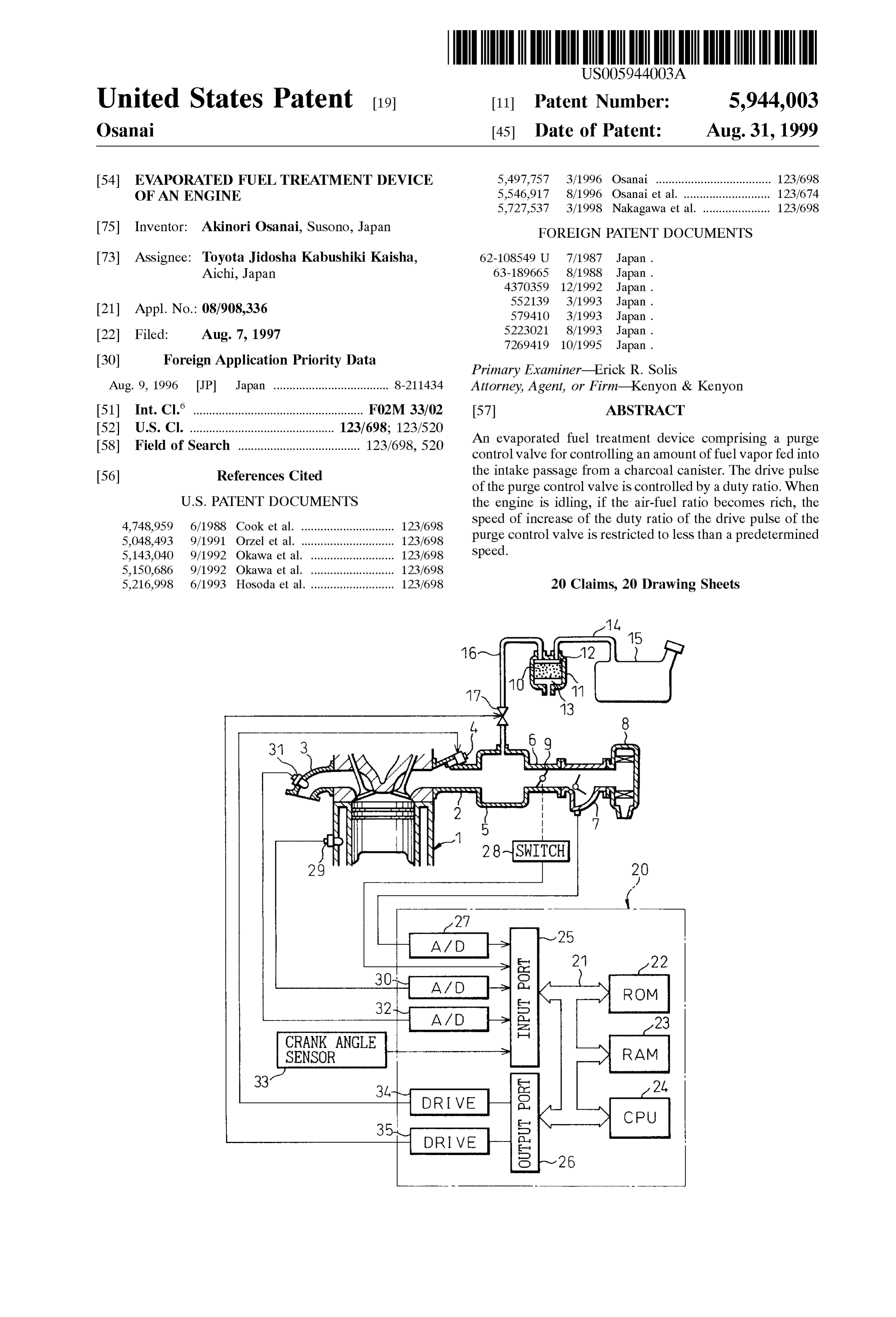
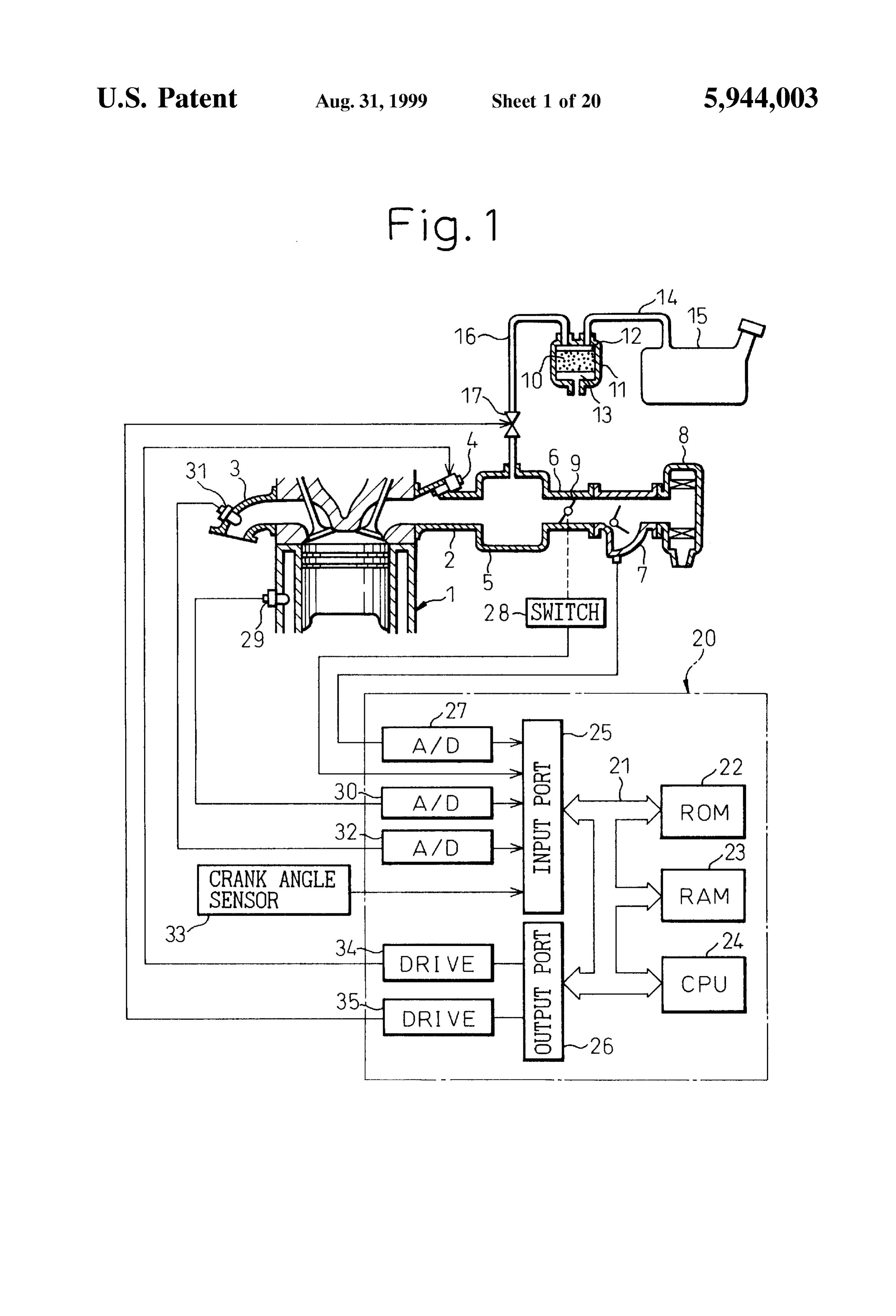
margin in this way, however, the air-fuel ratio will become 35 BRIEF DESCRIPTION OF THE DRAWINGS rich. If the air-fuel ratio becomes rich, the purge vapor concentration will Start to be calculated based on the amount These and other objects and features of the present of fluctuation of the air-fuel ratio, but it will take time until invention will become more apparent from the following the purge vapor concentration is accurately calculated. description of the preferred embodiments given with refer Therefore, for a while after the purge vapor concentration 40 ence to the attached drawings, in which: increases by a large margin, the air-fuel ratio will end up FIG. 1 is an overall view of an internal combustion deviating to the rich side with respect to the target air-fuel engine;
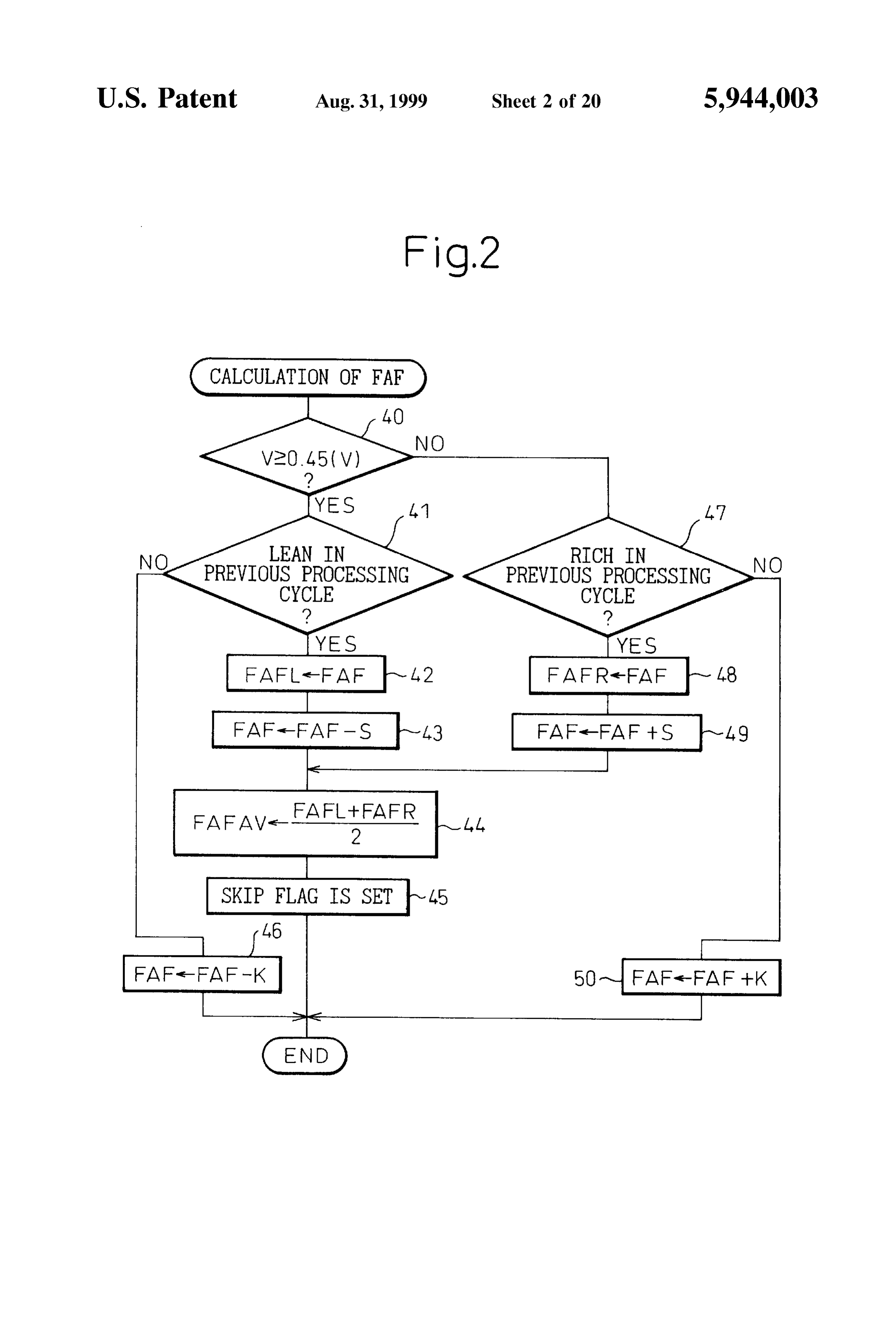
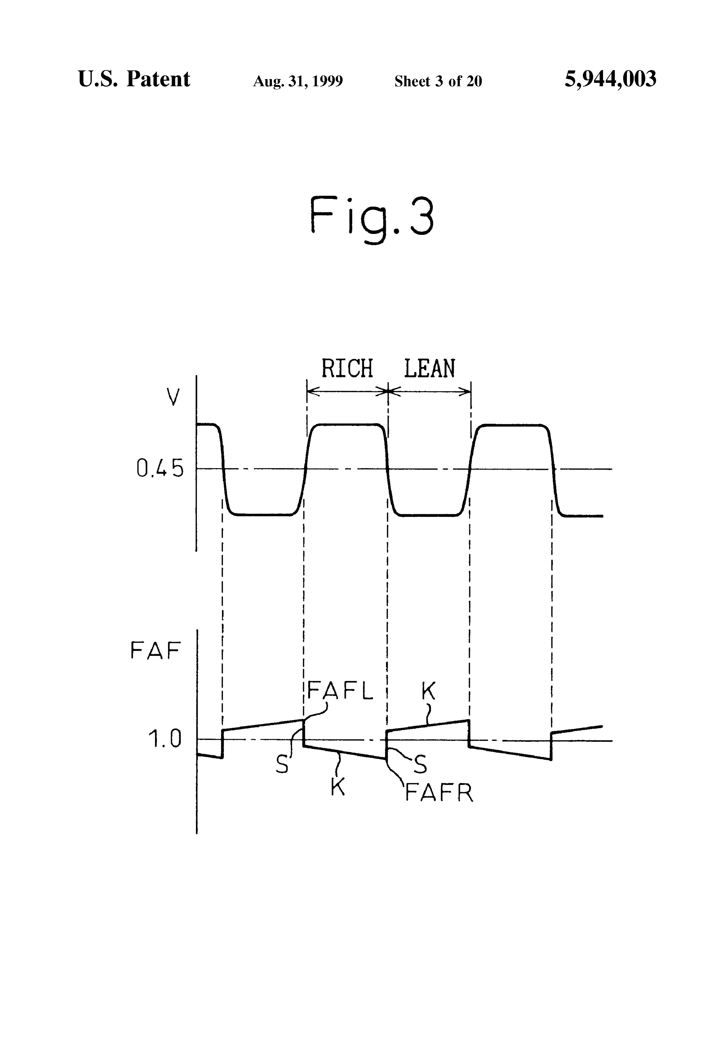
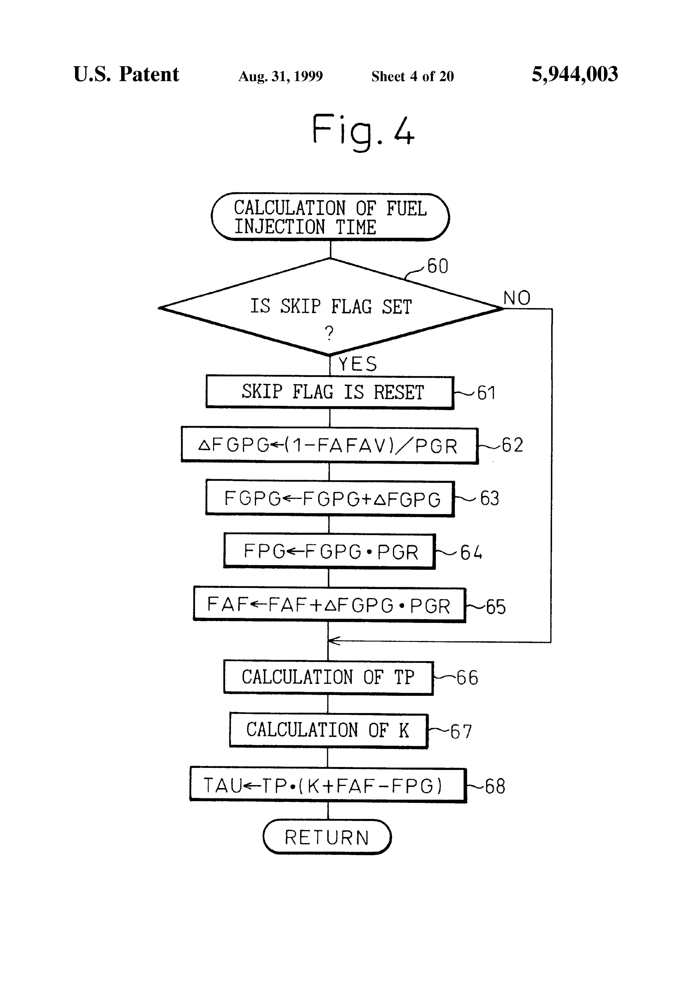
ratio. FIG. 2 is a flow chart of a routine for calculating an When the air-fuel ratio deviates to the rich side of the air-fuel ratio feedback correction coefficient FAF: target air-fuel ratio in this way, however, if the opening 45 FIG. 3 is a view of the changes in the air-fuel ratio degree of the purge control valve is increased rapidly, the feedback correction coefficient FAF:
amount of purge of a high concentration fuel vapor will be FIG. 4 is a flow chart of a routine for calculating a fuel rapidly increased and therefore the air-fuel ratio will shift injection time;
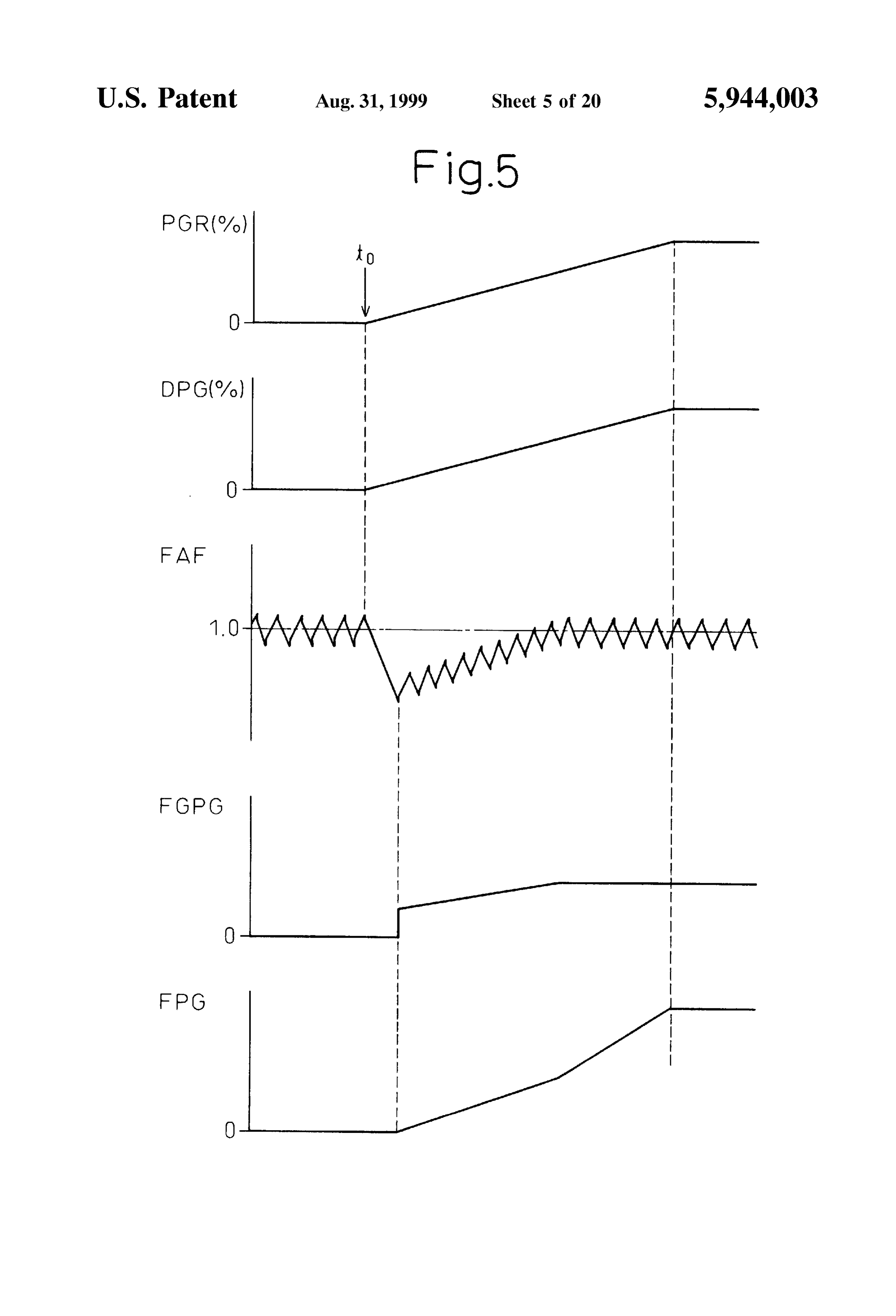
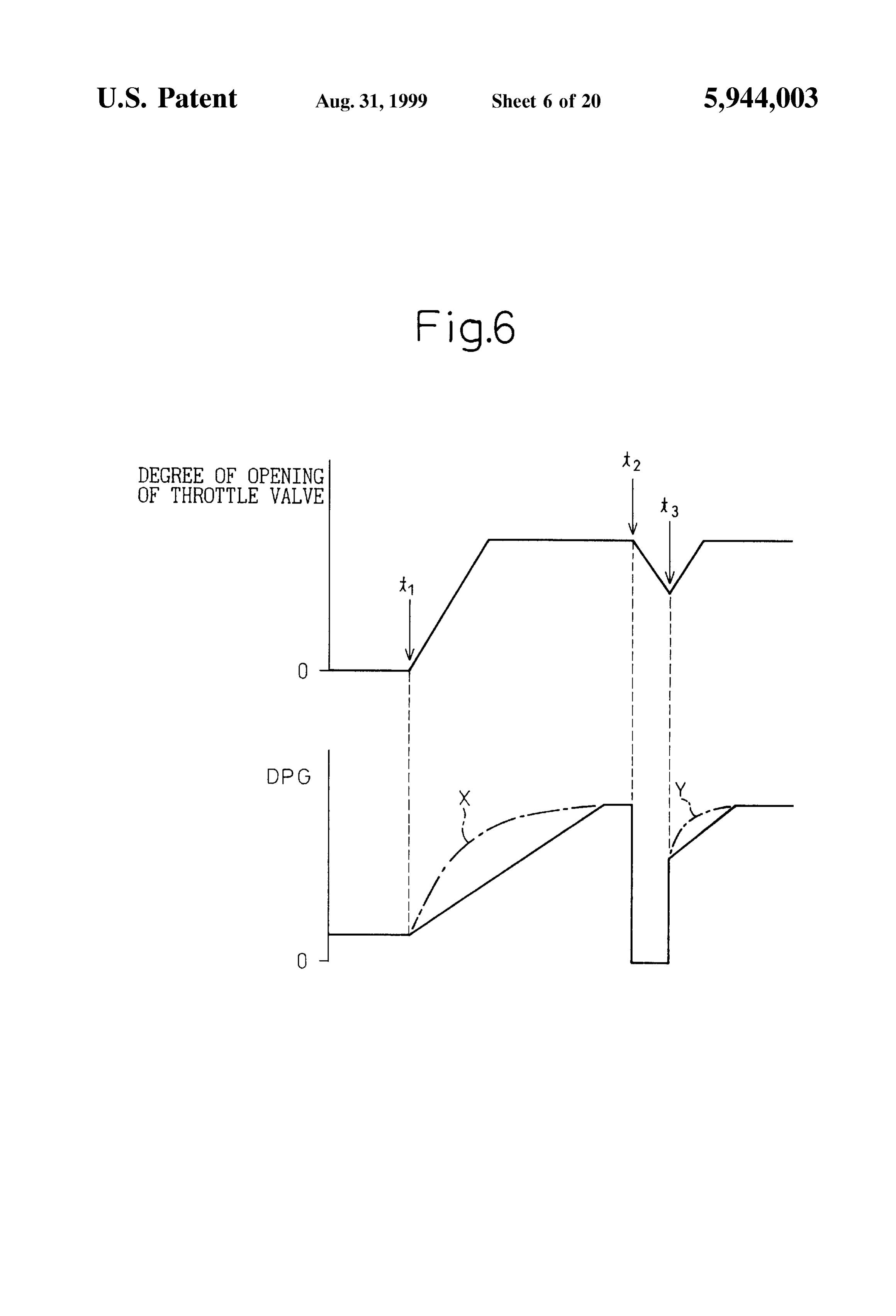
further to the rich side. Therefore, the air-fuel ratio will FIG. 5 is a view of changes in the purge vapor concen fluctuate widely. 50 tration FGPG etc.;
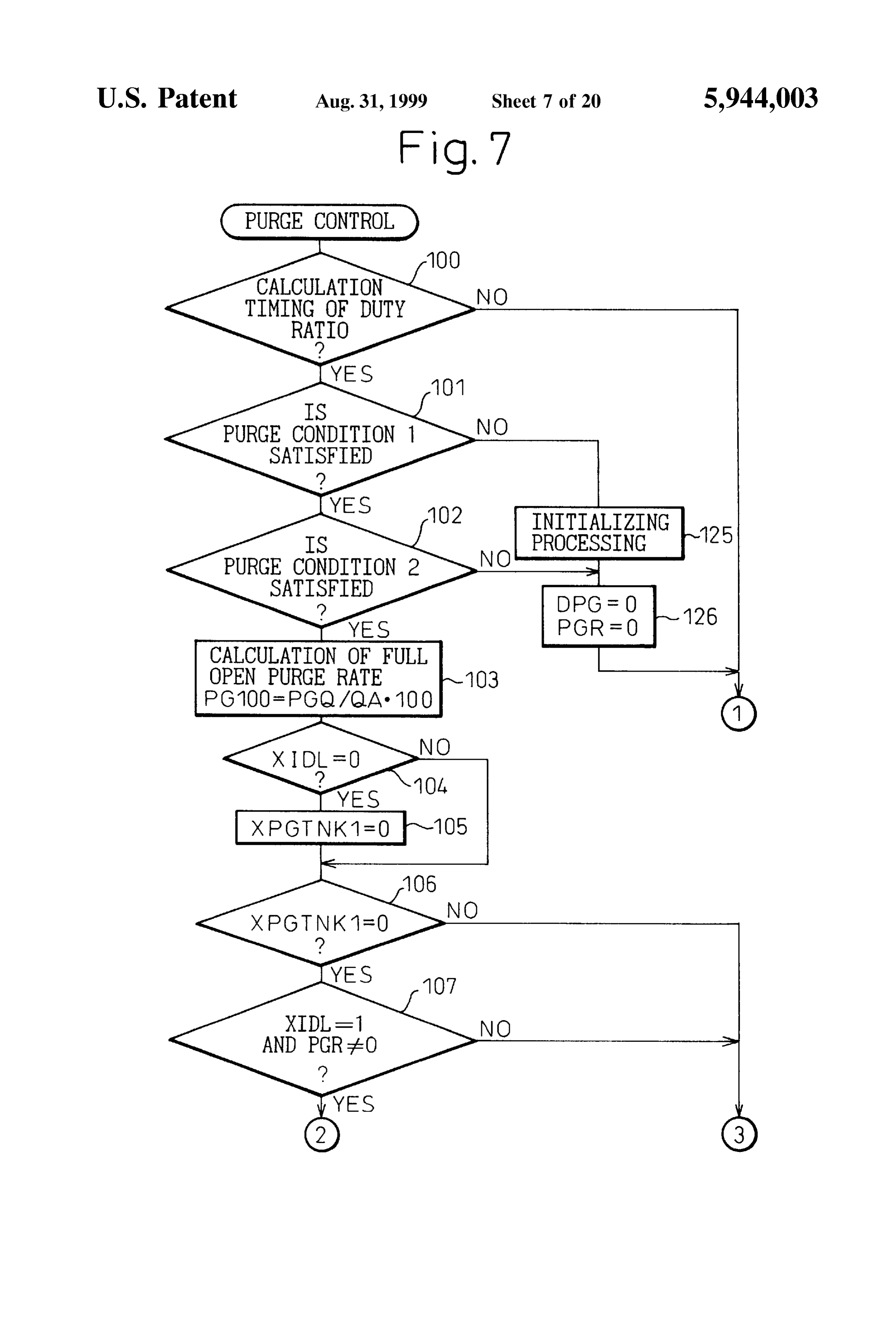
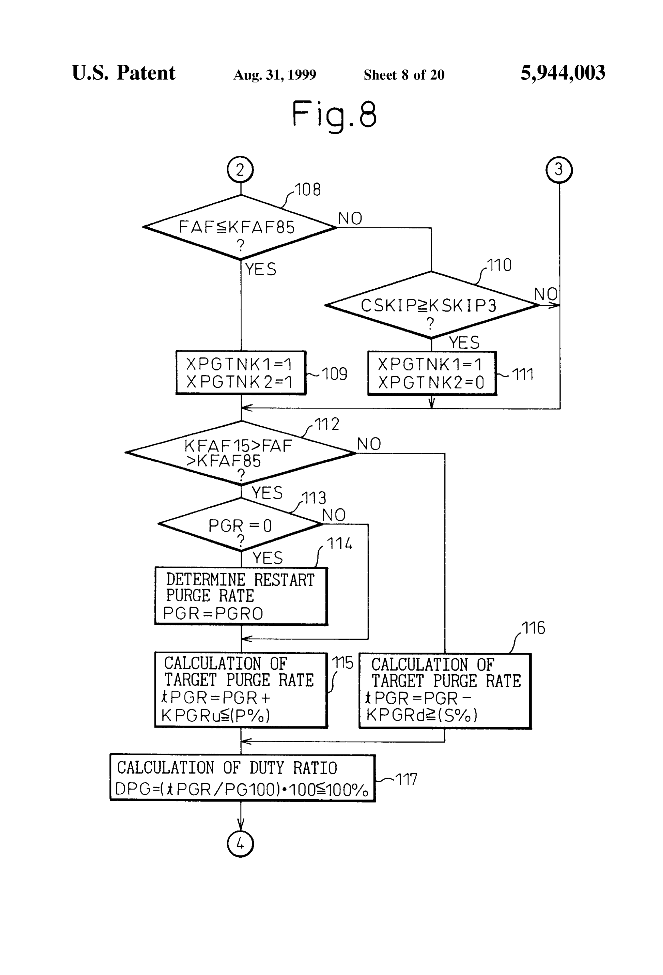
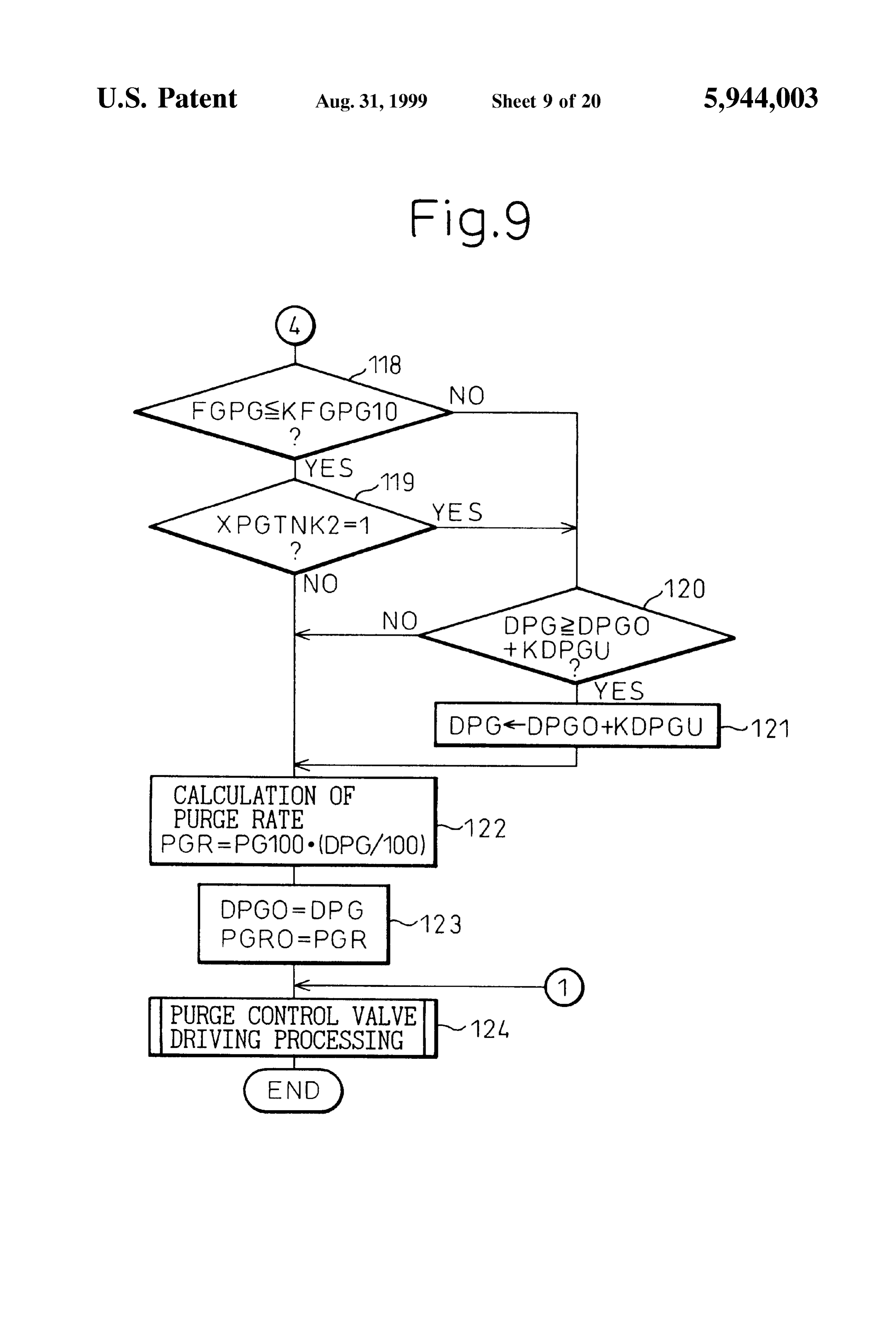
On the other hand, part of the evaporated fuel occurring FIG. 6 is a view of changes in a duty ratio DPG; in the fuel tank is adsorbed by the activated carbon in the FIGS. 7 to 9 are flow charts for the execution of a first canister, while the remaining evaporated fuel is directly fed into the engine intake passage. In this case, the evaporated embodiment of the purge control;
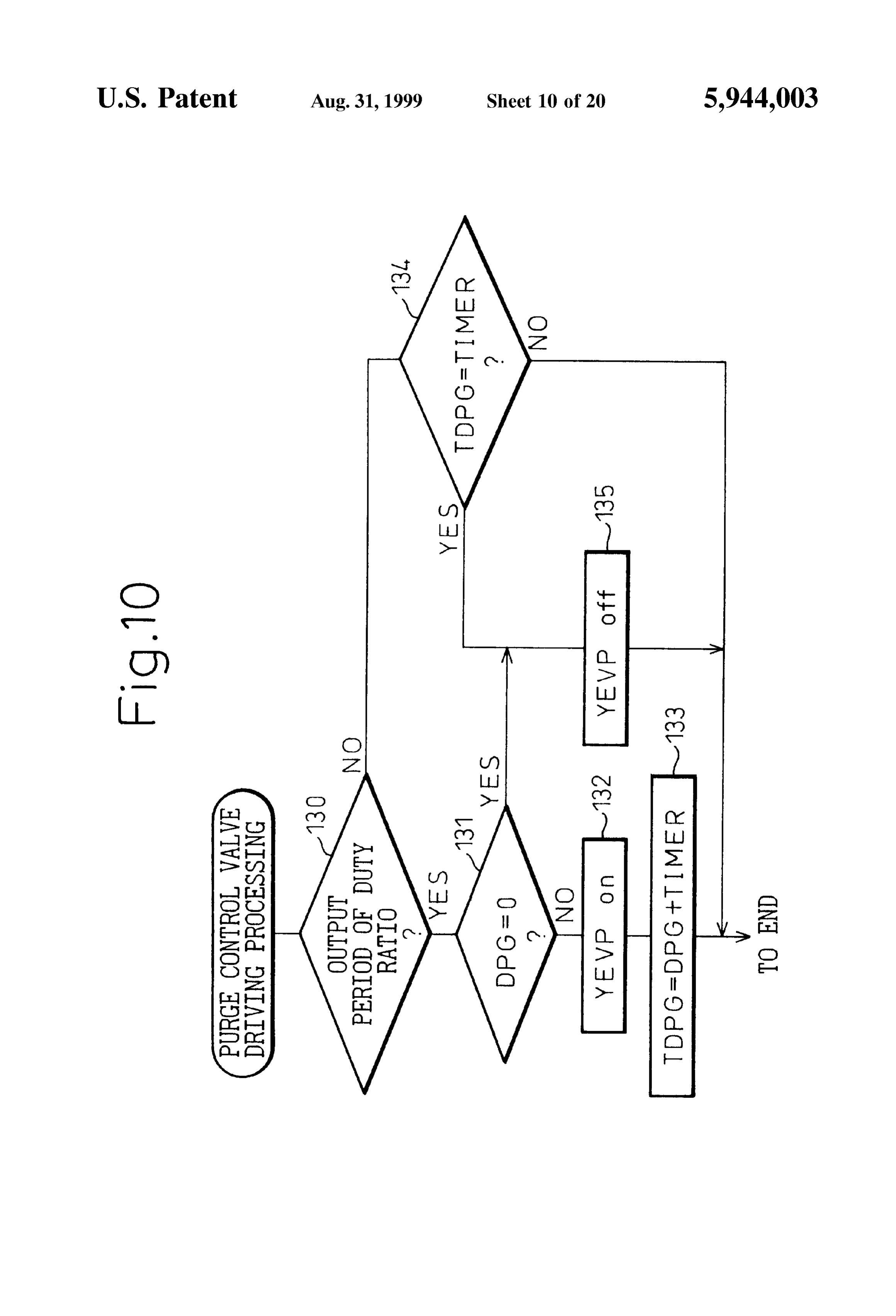
fuel fed from the fuel tank directly into the engine intake 55 FIG. 10 is a flow chart for the processing for driving the passage will depend not on the magnitude of the negative purge control valve;
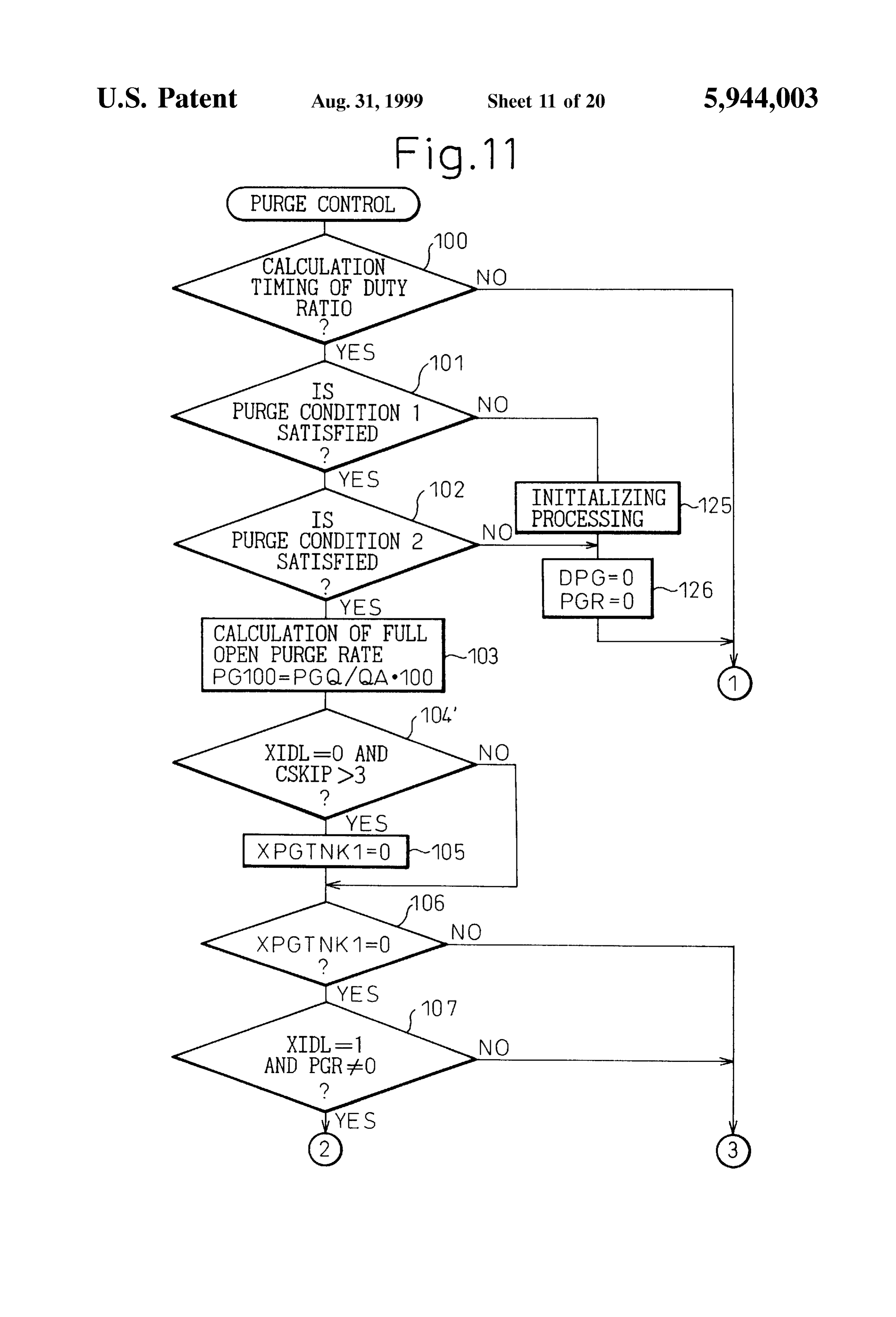
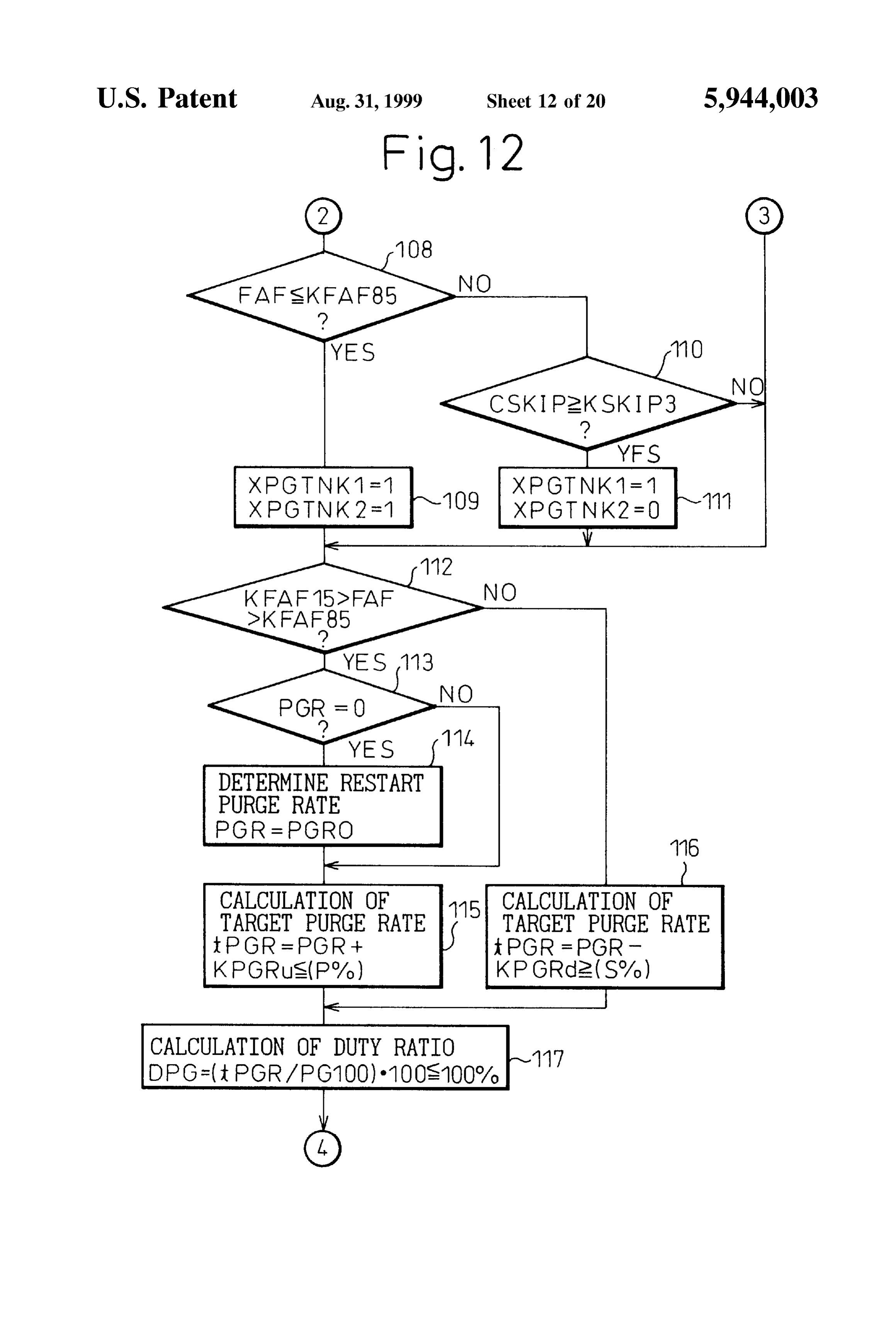
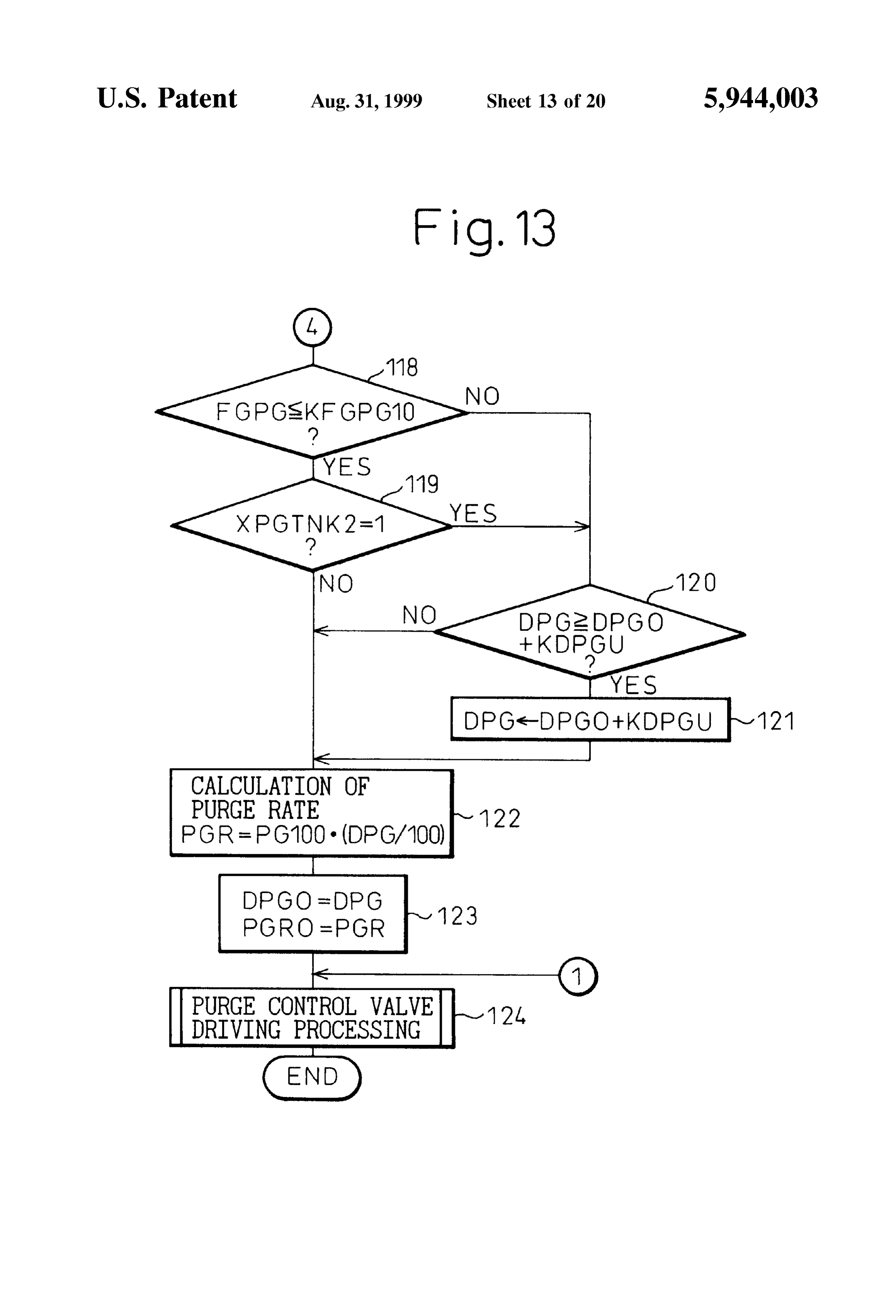
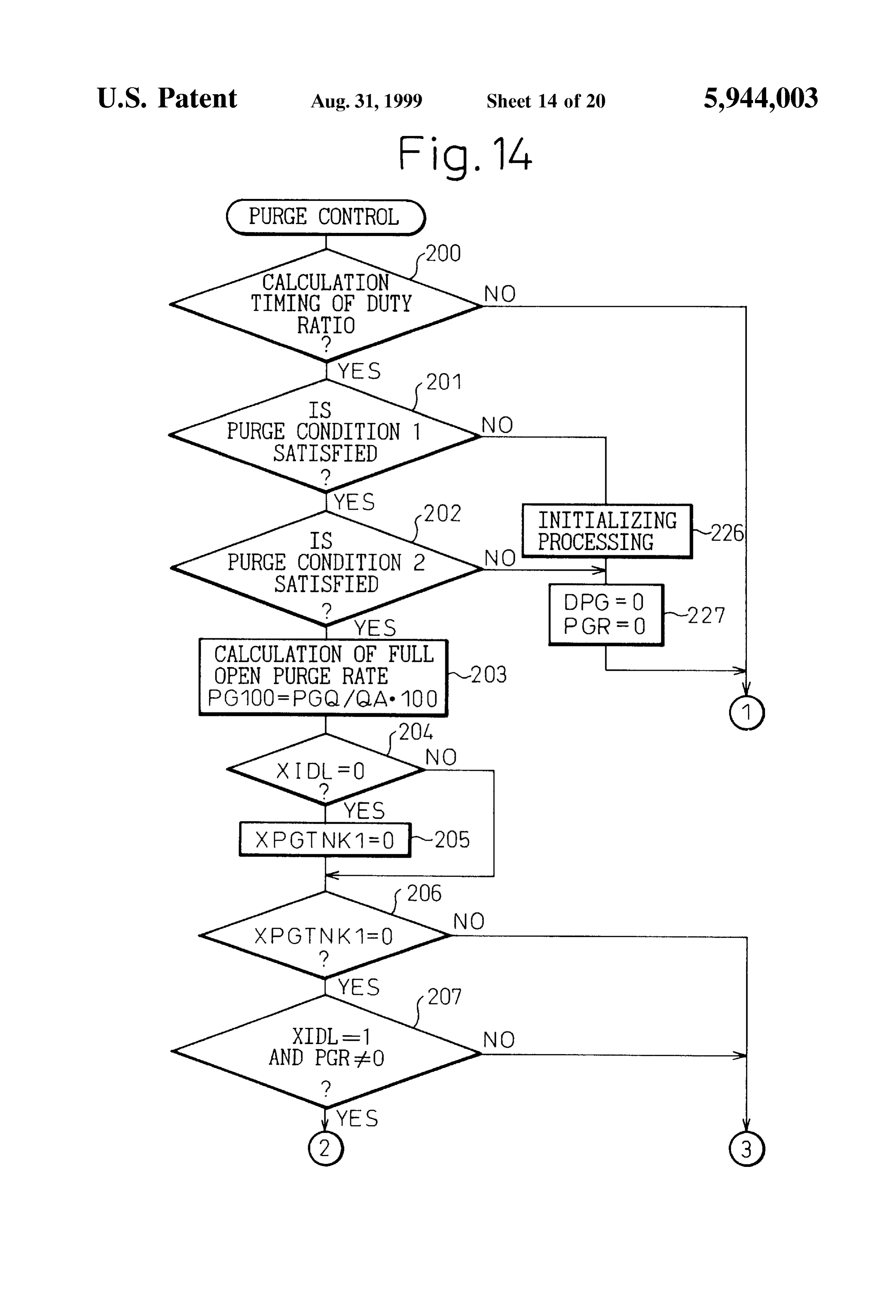
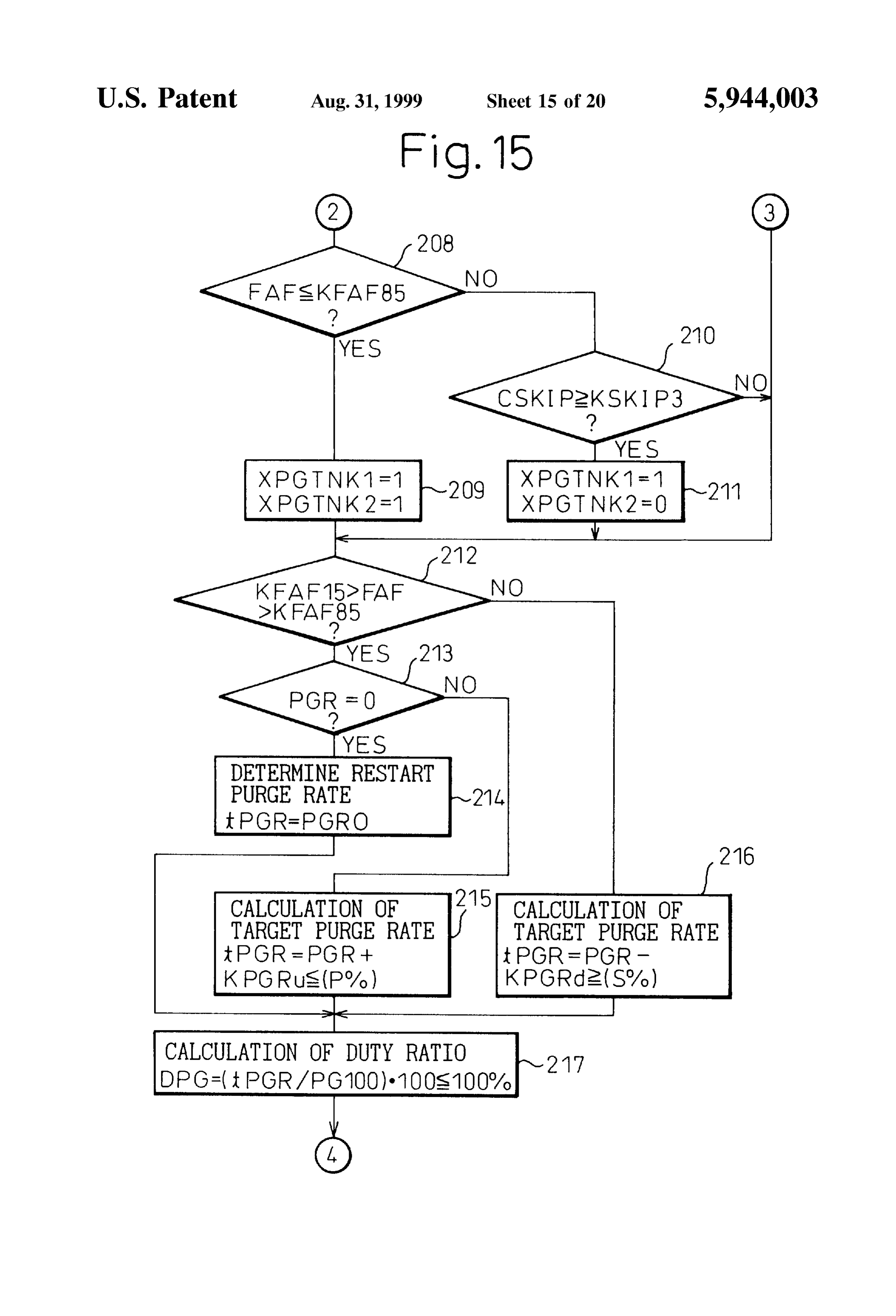
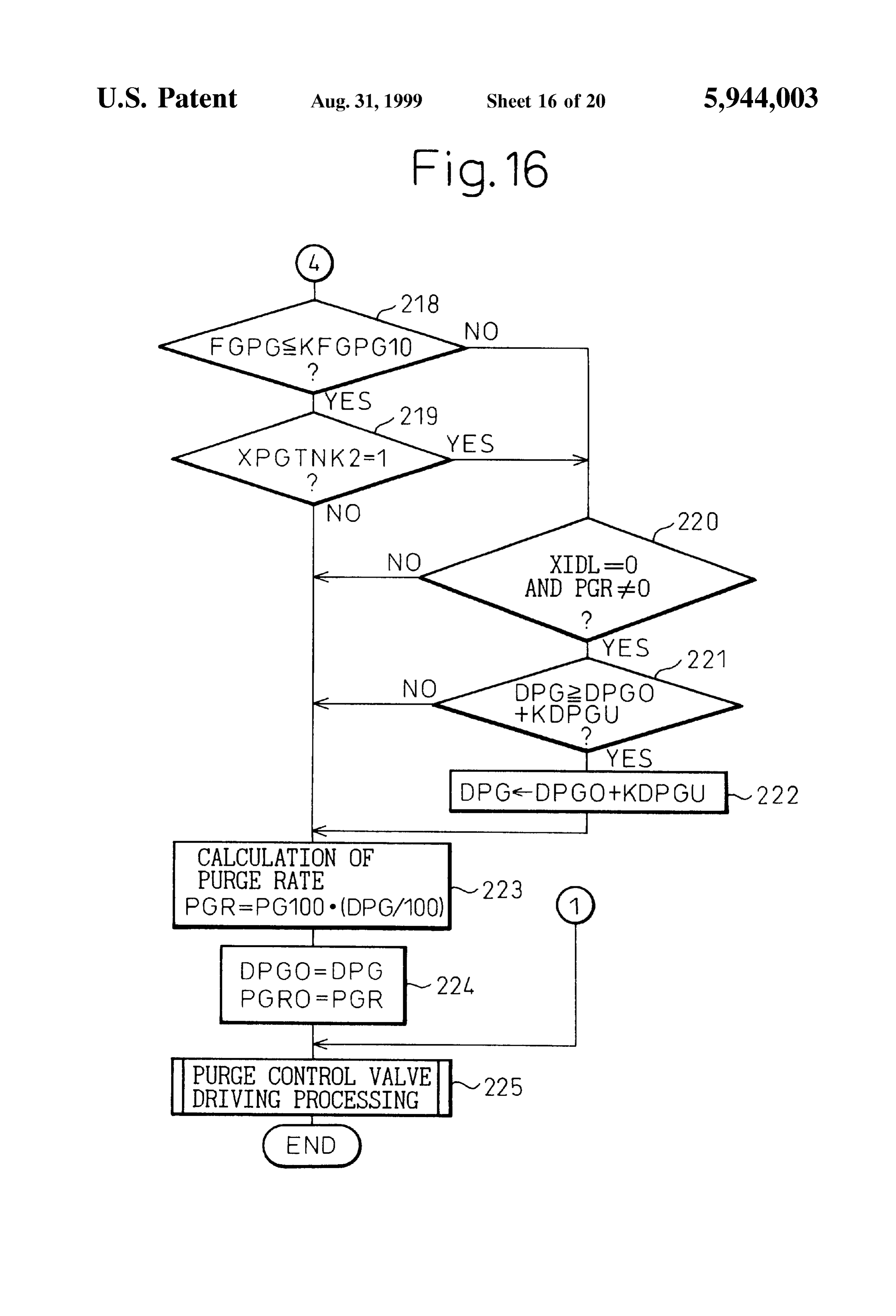
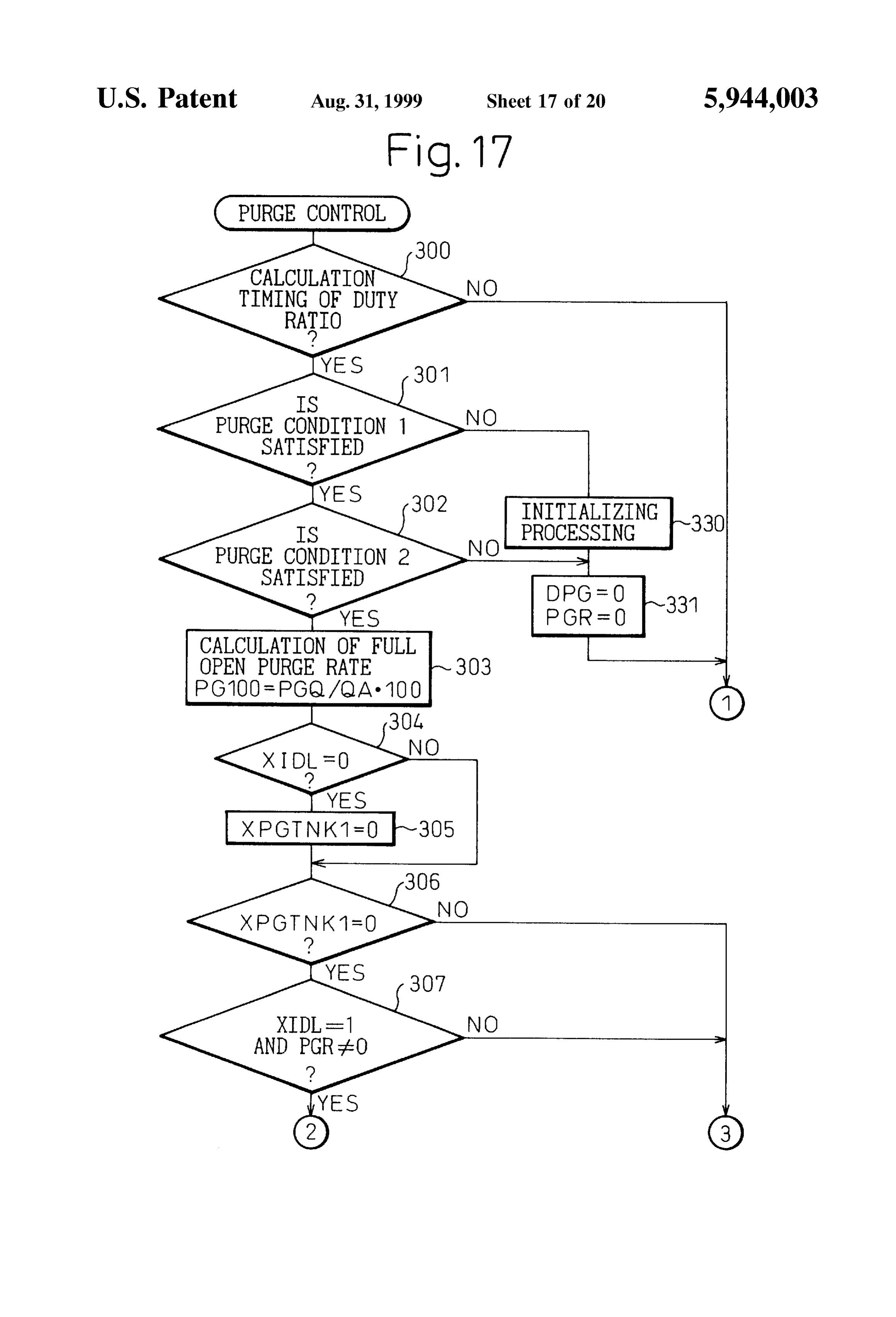
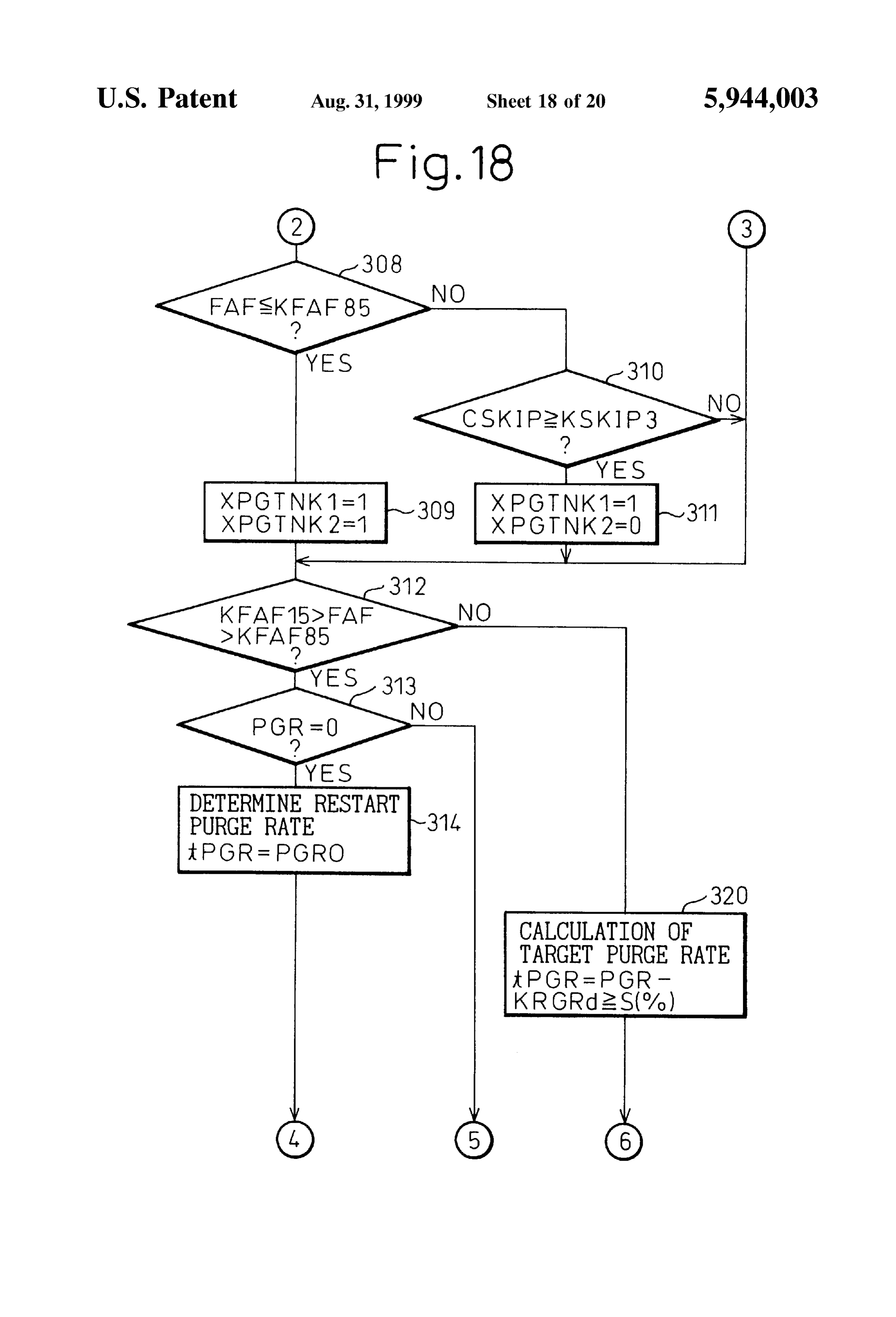
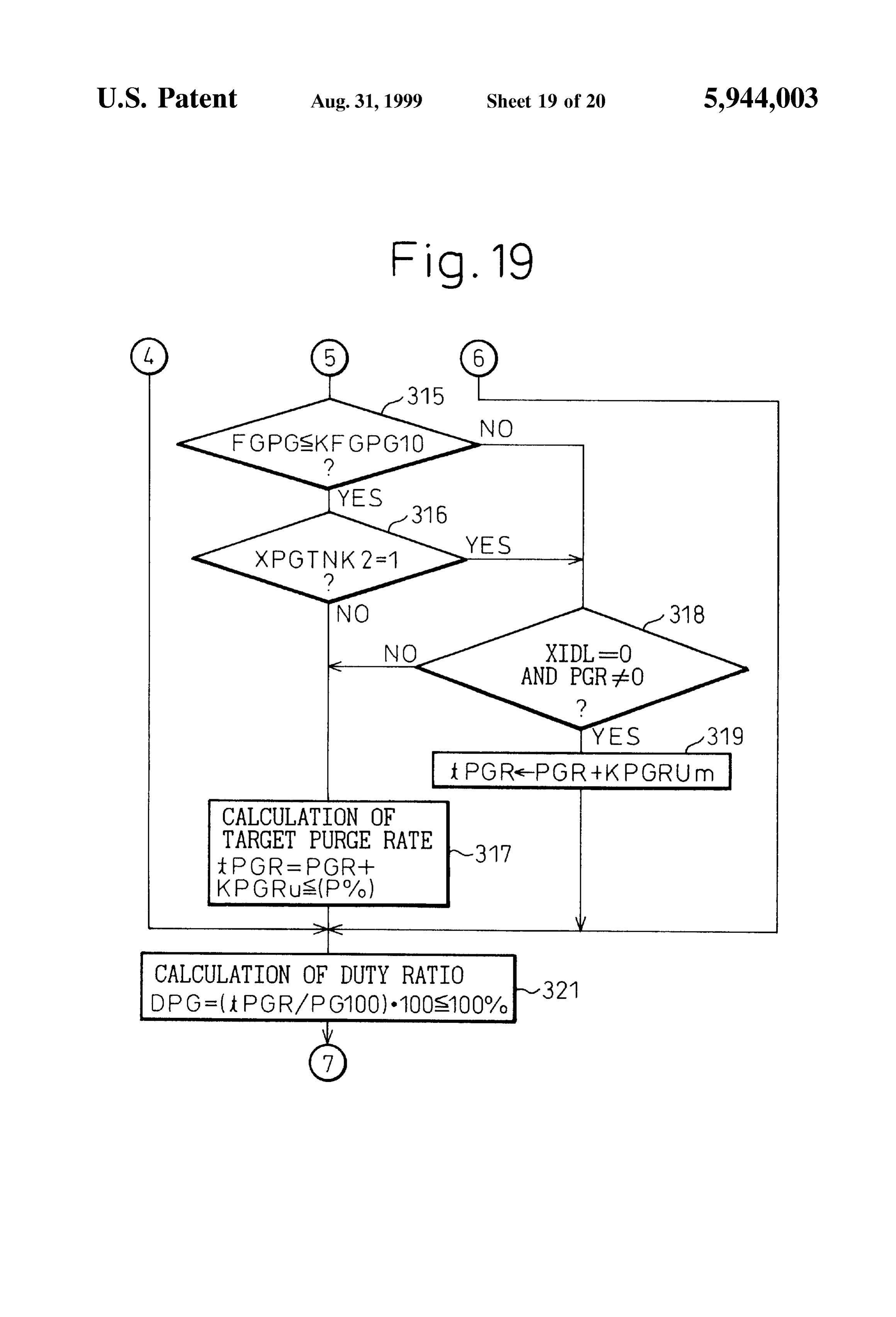
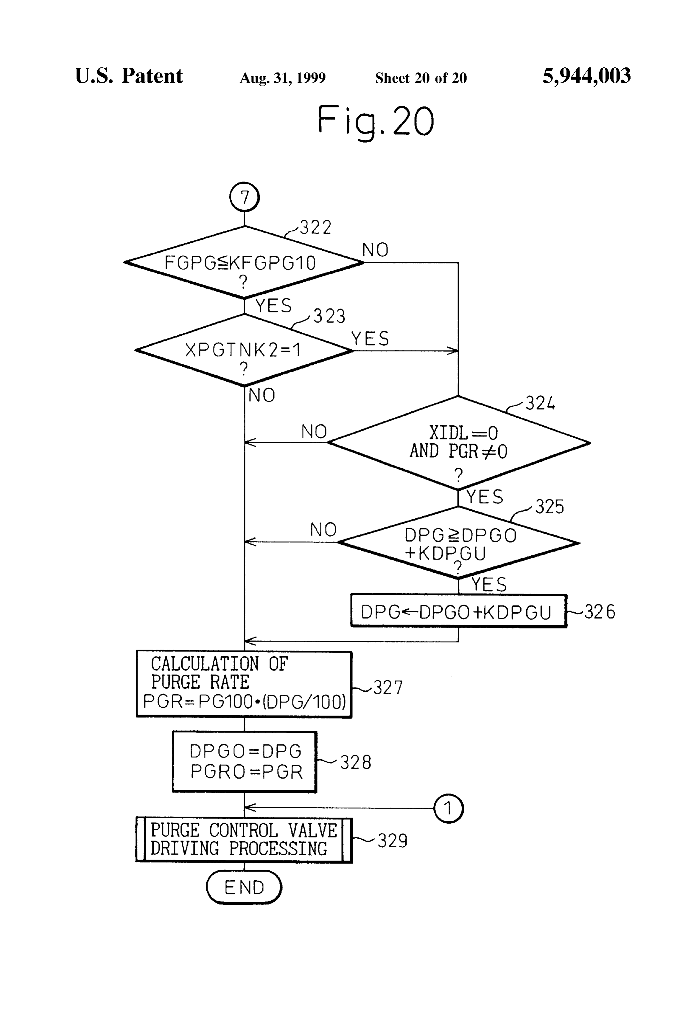
preSSure occurring in the intake passage, but will depend on FIGS. 11 to 13 are flow charts for the execution of a the amount of the evaporated fuel occurring in the fuel tank. Second embodiment of the purge control; Therefore, if the amount of intake air changes, for example, FIGS. 14 and 16 are flow charts for the execution of a if the amount of intake air increases, the amount of purge per 60 third embodiment of the purge control; and unit amount of intake air will decrease, So the purge vapor FIGS. 17 to 20 are flow charts for the execution of a fourth concentration will decrease by a large margin. As a result, embodiment of the purge control.
the air-fuel ratio will end up deviating to the lean Side of the target air-fuel ratio. DESCRIPTION OF THE PREFERRED When the air-fuel ratio deviates to the lean side of the 65 EMBODIMENTS target air-fuel ratio in this way, however, if the opening Referring to FIG. 1, 1 is an engine body, 2 an intake tube, degree of the purge control valve is rapidly increased, the 3 an exhaust manifold, and 4 a fuel injector attached to each
Page 23
of the intake pipes 2. Each intake pipe 2 is connected to a The purge A/F correction coefficient FPG is for correction common Surge tank 5. The Surge tank 5 is connected through of the amount of injection when the purge has been per an intake duct 6 and an air flow meter 7 to an air cleaner 8. formed. The period from when the engine operation is In the intake duct 6 is arranged a throttle valve 9. Further, as started to when the purge is started is FPG=0. shown in FIG. 1, the internal combustion engine has dis The feedback correction coefficient FAF is for controlling posed in it a canister 11 containing activated carbon 10. The the air-fuel ratio to the target air-fuel ratio based on the canister 11 has a fuel vapor chamber 12 and an atmospheric output signal of the air-fuel ratio Sensor 31. AS the target chamber 13 on the two sides of the activated carbon 10. The fuel vapor chamber 12 on the one hand is connected through air-fuel ratio, any air-fuel ratio may be used, but in the a conduit 14 to a fuel tank 15 and on the other hand through embodiment shown in FIG. 1, the target air-fuel ratio is a conduit 16 to the inside of the Surge tank 5. In the conduit made the Stoichiometric air-fuel ratio, therefore the expla 16 is disposed a purge control valve 17 which is controlled nation will be made of the case of making the target air-fuel by output signals from an electronic control unit 20. The fuel ratio the stoichiometric air-fuel ratio hereafter. Note that Vapor which is generated in the fuel tank 15 is sent through when the target air-fuel ratio is the Stoichiometric air-fuel the conduit 14 into the canister 11 where it is absorbed by the 15 ratio, as the air-fuel ratio Sensor 31, a Sensor whose output activated carbon 10. When the purge control valve 17 opens, Voltage changes in accordance with the concentration of the air is sent from the atmospheric chamber 13 through the oxygen in the exhaust gas is used, therefore hereinafter the activated carbon 10 into the conduit 16. When the air passes air-fuel ratio sensor 31 will be referred to as an O sensor. through the activated carbon 10, the fuel vapor which is This O sensor 31 generates an output voltage of about 0.9 absorbed in the activated carbon 10 is released from the V when the air-fuel ratio is rich and generates an output activated carbon 10 therefore air containing the fuel vapor is voltage of about 0.1 V when the air-fuel ratio is lean. First, purged through the conduit 16 to the inside of the Surge tank an explanation will be made of the control of the feedback 5. correction coefficient FAF performed based on the output The electronic control unit 20 is comprised of a digital Signal of this O. Sensor 31.
computer and is provided with a read only memory (ROM) FIG. 2 shows the routine for calculation of the feedback 22, a random access memory (RAM) 23, a microprocessor 25 correction coefficient FAF. This routine is executed for (CPU) 24, an input port 25, and an output port 26 connected example within a main routine.
to each other through a bidirectional bus 21. The air flow Referring to FIG. 2, first, at step 40, it is judged whether meter 7 generates an output voltage proportional to the the output voltage of the O sensor 31 is higher than 0.45 V amount of the intake air. This output Voltage is input through or not, that is, whether the air-fuel ratio is rich or not. When the AD converter 27 to the input port 25. The throttle valve V20.45 V, that is, when the air-fuel ratio is rich, the routine 9 has attached to it a throttle Switch 28 which becomes on proceeds to Step 41, where it is judged if the air-fuel ratio when the throttle valve 9 is at the idle open position. The was output signal of the throttle Switch 28 is input to the input lean at the time of the previous processing cycle or not. port 25. The engine body 1 has attached to it a water When cycle, it was lean at the time of the previous processing that is, when it has changed from lean to rich, the temperature Sensor 29 for generating an output voltage 35 proportional to the coolant water temperature of the engine. routine proceeds to Step 42, where the feedback control The output voltage of the water temperature sensor 29 is coefficient FAF is made FAFL and the routine proceeds to input through the AD converter 30 to the input port 25. The step 43. At step 43, a skip value S is subtracted from the exhaust manifold 3 has an air-fuel ratio sensor 31 attached feedback control coefficient FAF, therefore, as shown in to it. The output Signal of the air-fuel ratio Sensor 31 is input FIG. 3, the feedback control coefficient FAF is rapidly through the AD converter 32 to the input port 25. Further, the 40 reduced by the Skip value S. Next, at Step 44, the average input port 25 has connected to it a crank angle Sensor 33 value FAFAV of the FAFL and FAFR is calculated. Next, at generating an output pulse every time the crankshaft rotates step 45, the skip flag is set. On the other hand, when it is by for example 30 degrees. In the CPU 24, the engine speed judged at Step 41 that the air-fuel ratio was rich at the time is calculated based on this output pulse. On the other hand, of the previous processing cycle, the routine proceeds to Step the output port 26 is connected through the corresponding 45 46, where the integral value K(K-S) is subtracted from the drive circuits 34 and 35 to the fuel injectors 4 and the purge feedback control coefficient FAF. Therefore, as shown in control valve 17. FIG. 2, the feedback control coefficient FAF is gradually In the internal combustion engine shown in FIG. 1, the reduced.
fuel injection time TAU is calculated based fundamentally 50 On the other hand, when it is judged at step 40 that on the following equation: V<0.45 V, that is, when the air-fuel ratio is lean, the routine proceeds to Step 47, where it is judged if the air-fuel ratio was rich at the time of the previous processing cycle. When where, the coefficients show the following: it was rich at the time of the previous processing cycle, that TP: basic fuel injection time is, when it changed from rich to lean, the routine proceeds K: correction coefficient 55 to step 48, where the feedback control coefficient FAF is FAF: feedback correction coefficient made FAFR and the routine proceeds to step 49. At step 49, FPG: purge A/F correction coefficient the skip value S is added to the feedback control coefficient The basic fuel injection time TP is the experimentally FAF, therefore, as shown in FIG. 3, the feedback control found injection time required for making the air-fuel ratio coefficient FAF is rapidly increased by exactly the skip value the target air-fuel ratio. The basic fuel injection time TP is 60 S. Next, when it was judged at step 44 that the air-fuel ratio stored in advance in the ROM 22 as a function of the engine was lean at the time of the previous processing cycle, the load Q/N (amount of intake air Q/engine speed N) and the routine proceeds to step 50, where the integral value K is engine Speed N. added to the feedback control coefficient FAF. Therefore, as The correction coefficient Kexpresses the engine warmup shown in FIG. 3, the feedback control coefficient FAF is increase coefficient and the acceleration increase coefficient 65 gradually increased.
all together. When no upward correction is needed, K is When the air-fuel ratio becomes rich and FAF becomes made 0. smaller, the fuel injection time TAU becomes shorter, while
Page 24
S 6 when the air-fuel ratio becomes lean and the FAF increases, when the purge action is started, the duty ratio DPG of the the fuel injection time TAU becomes longer, So the air-fuel drive pulse with respect to the purge control valve 17 is ratio is maintained at the Stoichiometric air-fuel ratio. Note gradually increased, that is, the amount of opening of the that when the purge action is not performed, as shown in purge control valve 17 is gradually increased, So the fuel FIG. 3, the feedback control coefficient FAF fluctuates about purge rate PGR is gradually increased. On the other hand, 1.0. Further, as will be understood from FIG. 3, the average when the purge action of the fuel purge is started, normally value FAFAV calculated at step 44 shows the average value the ratio of the fuel in the intake air is increased, So the of the feedback control coefficient FAF. air-fuel ratio becomes richer by the amount of increase of the fuel ratio and as a result the feedback correction coefficient
AS will be understood from FIG. 3, the feedback control FAF becomes Smaller as shown in FIG. 5. coefficient FAF is made to change relatively slowly by the The amount of reduction of the feedback correction integral constant K, So if a large amount of fuel vapor is coefficient FAF corresponds to the amount of increase of the rapidly purged into the Surge tank 5 and the air-fuel ratio fuel ratio due to the purge action, that is, the amount of rapidly fluctuates, it no longer becomes possible to maintain increase of the purge vapor concentration FGPG per unit the air-fuel ratio at the Stoichiometric air-fuel ratio and purge rate, therefore if the feedback correction coefficient therefore the air-fuel ratio fluctuates. Therefore, in the 15 FAF falls, the purge vapor concentration FGPG will be embodiment shown in FIG. 1, to prevent the air-fuel ratio increased. Further, if the purge vapor concentration FGPG is from fluctuating, when the purge is performed, the amount increased, the purge A/F correction coefficient FPG will also of the purge is gradually increased. That is, in the embodi be gradually increased.
ment shown in FIG. 1, by controlling the duty ratio of the On the other hand, if the purge A/F correction coefficient drive pulse applied to the purge control valve 17, the amount FPG is increased, the feedback correction coefficient FAF of opening of the purge control valve 17 is controlled. When will be increased along with it. If the average value FAFAV the purge is started, the duty ratio of the drive pulse is of the feedback correction coefficient is returned to 1.0, the gradually increased. If the duty ratio of the drive pulse is purge vapor concentration FGPG will become a constant gradually increased in this way, that is, if the amount of value. At this time, the learning of the purge vapor concen purge is gradually increased, even during the increase in the 25 tration FGPG is ended. The purge vapor concentration amount of the purge, the air-fuel ratio will be maintained at FGPG at this time shows the actual purge vapor concentra the stoichiometric air-fuel ratio by the feedback control by tion in the intake air.
the feedback control coefficient FAF, therefore it is possible AS mentioned at the Start, however, when the air-fuel ratio to prevent the air-fuel ratio from fluctuating. deviates from the target air-fuel ratio, if the purge control Next, an explanation will be made of the routine for valve 17 is rapidly opened, the air-fuel ratio will fluctuate by calculation of the fuel injection time TAU referring to FIG. a large margin. Further, when the purge vapor concentration 4. This routine is executed repeatedly. FGPG is high, a fluctuation in the amount of purge will have Referring to FIG. 4, first, at Step 60, it is judged if the skip a large effect on the air-fuel ratio. Therefore, when the purge flag which is set at step 45 of FIG. 2 has been set or not. Vapor concentration is high, if the purge control valve 17 is When the Skip flag has not been Set, the routine jumps to Step 35 rapidly opened, the air-fuel ratio will fluctuate by a large 66. AS opposed to this, when the Skip flag has been Set, the margin. Accordingly, in this embodiment of the present routine proceeds to Step 61, where the Skip flag is reset, then invention, when the air-fuel ratio deviates from the target the routine proceeds to Step 62, where the purge vapor air-fuel ratio and when the purge vapor concentration FGPG concentration AFPGA per unit purge rate is calculated based is high, the Speed of opening of the purge control valve 17 on the following formula: 40 is restricted to less than a predetermined speed. Next,an explanation will be made of the control of the
Speed of opening of the purge control valve 17 according to
That is, the amount of fluctuation (1-FAFAV) of the the present invention referring to FIG. 6 showing the rela average air-fuel ratio FAFAV shows the purge vapor con tionship between the throttle opening degree and the duty centration therefore by dividing (1-FAFAV) by the purge 45 ratio DPG of the drive pulse of the purge control valve 17. rate PGR, the purge vapor concentration AFPGA per unit As shown in FIG. 6, at the time t, when the throttle purge rate is calculated. Note that the purge rate PGR opening degree is increased from the idling opening degree, expresses the actual purge rate of the fuel vapor. This purge normally the duty ratio DPG is made to rise sharply as rate PGR is calculated in a routine explained later. shown by the broken line X. That is, the amount of opening Next, at step 63, the purge vapor concentration AFPGA is 50 of the purge control valve 17 is rapidly increased. At this added to the purge vapor concentration FPGA to update the time, however, if the air-fuel ratio deviates from the target purge vapor concentration FPGA per unit purge rate. When air-fuel ratio or the purge vapor concentration FGPG is high, FAFAV approaches 1.0, AFPGA approaches zero, therefore the speed of increase of the duty ratio DPG is restricted as FPGA approaches a constant value. Next, at step 64, the shown by the solid line so that the duty ratio DPG is purge rate PGR is multiplied with FPGA to calculate the 55 increased by a constant Speed of opening.
purge A/F correction coefficient FPG (=FPGA-PGR). Next, Next, when a deceleration operation is started at the time at step 65, AFPGAPGR is added to FAF So as to increase the t and the fuel injection is stopped, the duty ratio DPG is feedback control coefficient FAF by exactly the amount of made Zero. That is, the purge control valve 17 is closed and the increase of the purge A/F correction coefficient FPG. the use of a purge operation is Stopped.
Next, at step 66, the basic fuel injection time TP is 60 Next, when the throttle opening degree is again increased calculated, then at Step 67, the correction coefficient K is at the time t, the duty ratio DPG normally is made to rapidly calculated, then at step 68, the injection time TAU (=TP. rise as shown by the broken line Y. If the air-fuel ratio (k+FAF=FPG)) is calculated. deviates from the target air-fuel ratio at this time or the purge FIG. 5 shows the changes in the purge vapor concentra Vapor concentration FGPG is high, the Speed of increase of tion FGPG and the purge A/F correction coefficient FPG per 65 the duty ratio DPG is restricted as shown by the solid line so unit purge rate at the time when the purge action is started that the duty ratio DPG is increased by a constant speed of at the time to. In this embodiment of the present invention, opening.
Page 25
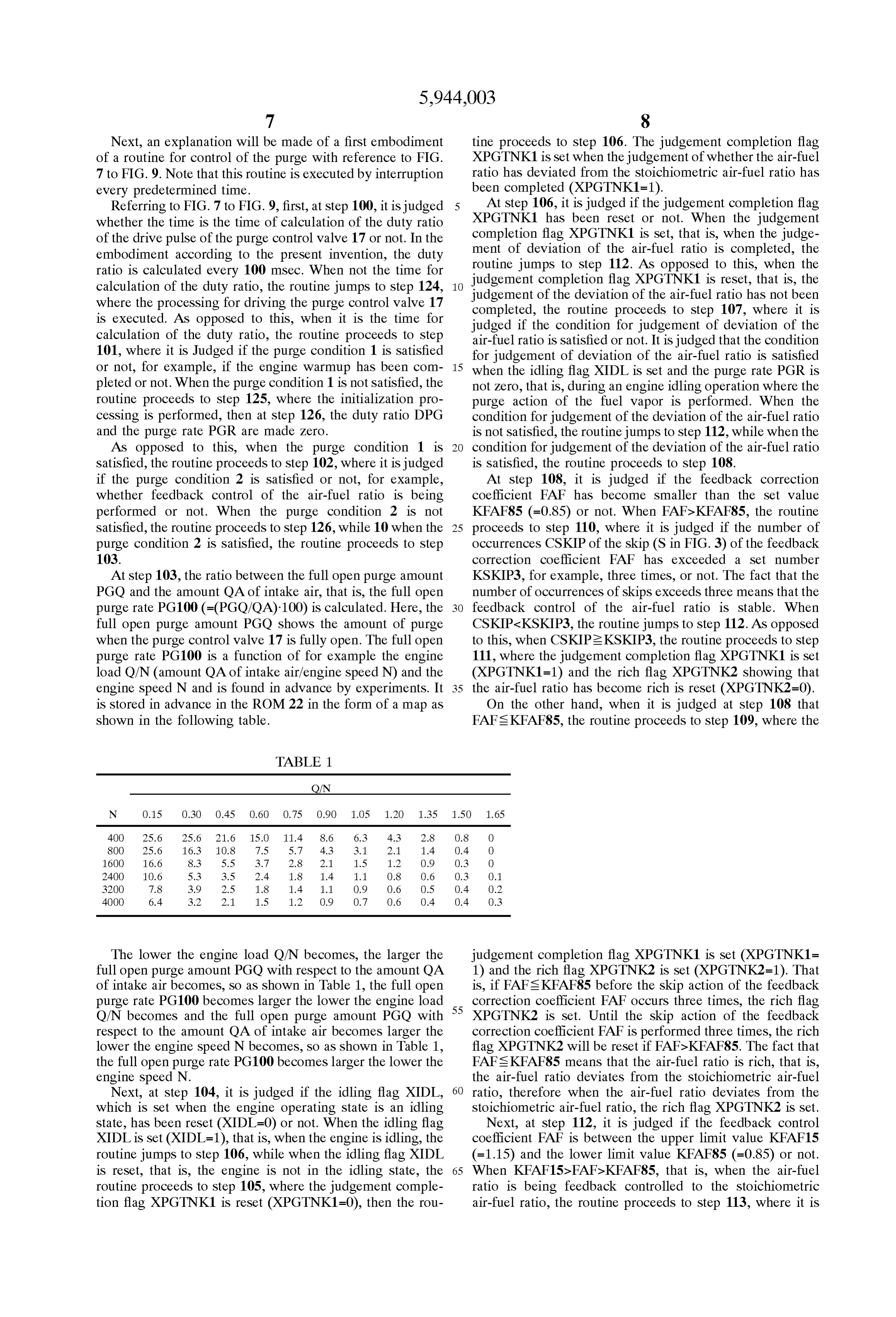
Next, an explanation will be made of a first embodiment tine proceeds to Step 106. The judgement completion flag of a routine for control of the purge with reference to FIG. XPGTNK1 is set when the judgement of whether the air-fuel 7 to FIG. 9. Note that this routine is executed by interruption ratio has deviated from the Stoichiometric air-fuel ratio has every predetermined time. been completed (XPGTNK1=1).
Referring to FIG. 7 to FIG.9, first, at step 100, it is judged At Step 106, it is judged if the judgement completion flag whether the time is the time of calculation of the duty ratio XPGTNK1 has been reset or not. When the judgement of the drive pulse of the purge control valve 17 or not. In the completion flag XPGTNK1 is set, that is, when the judge embodiment according to the present invention, the duty ment routine of deviation of the air-fuel ratio is completed, the jumps to Step 112. AS opposed to this, when the ratio is calculated every 100 msec. When not the time for judgement completion flag XPGTNK1 is reset, that is, the calculation of the duty ratio, the routine jumps to Step 124, where the processing for driving the purge control valve 17 judgement of the deviation of the air-fuel ratio has not been completed, the routine proceeds to step 107, where it is is executed. AS opposed to this, when it is the time for judged calculation of the duty ratio, the routine proceeds to Step air-fuel ifratio the condition for judgement of deviation of the is Satisfied or not. It is judged that the condition 101, where it is Judged if the purge condition 1 is satisfied for judgement of deviation of the air-fuel ratio is Satisfied or not, for example, if the engine warmup has been com 15 when the idling flag XIDL is set and the purge rate PGR is pleted or not. When the purge condition 1 is not satisfied, the not Zero, that is, during an engine idling operation where the routine proceeds to Step 125, where the initialization pro purge action of the fuel vapor is performed. When the cessing is performed, then at step 126, the duty ratio DPG condition for judgement of the deviation of the air-fuel ratio and the purge rate PGR are made Zero. is not Satisfied, the routine jumps to Step 112, while when the AS opposed to this, when the purge condition 1 is condition for judgement of the deviation of the air-fuel ratio Satisfied, the routine proceeds to Step 102, where it is judged is satisfied, the routine proceeds to step 108. if the purge condition 2 is Satisfied or not, for example, At step 108, it is judged if the feedback correction whether feedback control of the air-fuel ratio is being coefficient FAF has become Smaller than the set value performed or not. When the purge condition 2 is not KFAF85 (=0.85) or not. When FAF>KFAF85, the routine satisfied, the routine proceeds to step 126, while 10 when the 25 proceeds to step 110, where it is judged if the number of purge condition 2 is Satisfied, the routine proceeds to Step occurrences CSKIP of the skip (S in FIG. 3) of the feedback 103. correction coefficient FAF has exceeded a set number At step 103, the ratio between the full open purge amount KSKIP3, for example, three times, or not. The fact that the PGQ and the amount QA of intake air, that is, the full open number of occurrences of skips exceeds three means that the purge rate PG100 (=(PGQ/QA)-100) is calculated. Here, the feedback control of the air-fuel ratio is stable. When full open purge amount PGO shows the amount of purge CSKIP<KSKIP3, the routine jumps to step 112. As opposed when the purge control valve 17 is fully open. The full open to this, when CSKIP2KSKIP3, the routine proceeds to step purge rate PG100 is a function of for example the engine 111, where the judgement completion flag XPGTNK1 is set load Q/N (amount QA of intake air/engine speed N) and the (XPGTNK1=1) and the rich flag XPGTNK2 showing that engine Speed N and is found in advance by experiments. It 35 the air-fuel ratio has become rich is reset (XPGTNK2=0). is stored in advance in the ROM 22 in the form of a map as On the other hand, when it is judged at step 108 that shown in the following table. FAFs KFAF85, the routine proceeds to step 109, where the
TABLE 1.
OfN
N O.15 O3O O.45 0.6O O.75 O.90 1.OS 1.2O 1.35 1.5O 1.65 4OO 25.6 25.6 21.6 15.O 11.4 8.6 6.3 4.3 2.8 O.8 O 8OO 25.6 16.3 10.8 7.5 5.7 4.3 3.1 2.1 1.4 O.4 O 1600 16.6 8.3 5.5 3.7 2.8 2.1 1.5 12 O.9 O.3 O 2400 10.6 5.3 3.5 2.4 1.8 1.4 1.1 O.8 O6 O.3 O1 32OO 7.8 3.9 2.5 18 1.4 1.1 O.9 O6 0.5 O.4 O2 4OOO 6.4 3.2 2.1 1.5 12 O.9 O.7 O.6 0.4 O.4 O.3
The lower the engine load Q/N becomes, the larger the judgement completion flag XPGTNK1 is set (XPGTNK1= full open purge amount PGO with respect to the amount QA 1) and the rich flag XPGTNK2 is set (XPGTNK2=1). That of intake air becomes, So as shown in Table 1, the full open is, if FAFs KFAF85 before the skip action of the feedback purge rate PG100 becomes larger the lower the engine load 55 correction coefficient FAF occurs three times, the rich flag Q/N becomes and the full open purge amount PGO with XPGTNK2 is set. Until the skip action of the feedback respect to the amount QA of intake air becomes larger the correction coefficient FAF is performed three times, the rich lower the engine Speed N becomes, So as shown in Table 1, flag XPGTNK2 will be reset if FAF>KFAF85. The fact that the full open purge rate PG100 becomes larger the lower the FAFSKFAF85 means that the air-fuel ratio is rich, that is, engine Speed N. the air-fuel ratio deviates from the stoichiometric air-fuel Next, at step 104, it is judged if the idling flag XIDL, 60 ratio, therefore when the air-fuel ratio deviates from the which is Set when the engine operating State is an idling stoichiometric air-fuel ratio, the rich flag XPGTNK2 is set. state, has been reset (XIDL=0) or not. When the idling flag Next, at step 112, it is judged if the feedback control XIDL is set (XIDL=1), that is, when the engine is idling, the coefficient FAF is between the upper limit value KFAF15 routine jumps to step 106, while when the idling flag XIDL (=1.15) and the lower limit value KFAF85 (=0.85) or not. is reset, that is, the engine is not in the idling state, the 65 When KFAF15>FAF>KFAF85, that is, when the air-fuel routine proceeds to Step 105, where the judgement comple ratio is being feedback controlled to the Stoichiometric tion flag XPGTNK1 is reset (XPGTNK1 =0), then the rou air-fuel ratio, the routine proceeds to Step 113, where it is
Page 26
judged whether the purge rate PGR is zero or not. That is, step 119 that the rich flag XPGTNK2 is set, that is, the when the purge action is being performed, PGR>0, So at this air-fuel ratio deviates from the Stoichiometric air-fuel ratio, time the routine jumps to Step 115. AS opposed to this, when the routine proceeds to step 120. the purge action has not started, the routine proceeds to Step At step 120, it is judged if the duty ratio DPG calculated 114, where the purge rate PGR0 is made the restart purge at step 117 is larger than the value of the previously rate PGR. When the purge condition 1 and the purge calculated duty ratio DPG0 plus a constant value KDPGU condition 2 are satisfied for the first time since the start of (DPG0+KDPGU) or not. Here, the constant value KDPGU operation of the engine, the purge rate PGR0 is made Zero is a value for restricting the Speed of opening of the purge by the initialization processing (step 125), So at this time control valve 17 and therefore is a relatively small value. PGR=0. As opposed to this, when the purge action has been When DPGCDPG0+KDPGU, the routine jumps to step 122, Suspended once and then the purge control is resumed, the while when DPG2DPG0+KDPGU, the routine proceeds to purge rate PGR0 at the time when the purge control had been step 121 where (DPG0+KDPGU) is made the duty ratio Suspended is made the restart purge rate PGR. DPG. Next, the routine proceeds to step 122. Next, at step 115, the target purge rate tRGR (=PGR-- That is, when the duty ratio DPG increases by only less KPRGu) is calculated by adding a constant value KPGRu to 15 than the constant value KDPGU, the duty ratio calculated at the purge rate PGR. That is, when KFAF15>FAF>KFAF85, step 117 is used as it is as the duty ratio. When the duty ratio it is understood, the target purge rate t?GR is gradually DPG increases by more than the constant value KDPGU, the increased every 100 msec. Note that an upper limit value P amount of increase of the duty ratio DPG is controlled to the (P is for example 6%) is set for this target purge rate tRGR, constant value KDPGU. In other words, when the speed of therefore the target purge rate t?GR can only rise up to this opening of the purge control valve 17 becomes more than a upper limit value P. Next, the routine proceeds to step 117. constant Speed, the Speed of opening of the purge control On the other hand, when it is judged at step 112 that Valve 17 is restricted to a constant Speed. FAFeKFAF15 or FAFs KFAF85, the routine proceeds to At step 122, the full open rate PG100 is multiplied by the step 116, where the constant value KPGRd is subtracted duty ratio DPG to calculate the actual purge rate PGR from the purge rate PGR to calculate the target purge rate 25 (=PG100-(DPG/100)). That is, as explained above, the duty tPGR (=PGR-KPGRd). That is, when the air-fuel ratio ratio DPG is expressed by (tPGR/PG100): 100. In this case, cannot be maintained at the Stoichiometric air-fuel ratio due when the target purge rate tpGR becomes larger than the full to the purge action of the fuel vapor, the target purge rate open purge rate PG100, the duty ratio DPG would become tPGR is reduced. Note that a lower limit value S (S=0%) is more than 100 percent. The duty ratio DPG, however, cannot Set for the target purge rate t?GR. Next, the routine proceeds become more than 100 percent. At this time, the duty ratio to step 117. DPG is made 100 percent, therefore the actual purge rate At step 117, the target purge rate tRGR is divided by the PGR becomes Smaller than the target purge rate tRGR. full open purge rate PG100 to calculate the duty ratio DPG Accordingly, the actual purge rate PGR is expressed by (=(tPGR/PG100): 100) of the drive pulse of the purge control PG100-(DPG/100) as explained above. valve 17. Therefore, the duty ratio DPG of the drive pulse of 35 Next, at step 123, the duty ratio DPG is made DPG0 and the purge control valve 17, that is, the amount of opening of the purge rate PGR is made PGR0. Next, at step 124, the purge control valve 17, is controlled in accordance with processing is performed to drive the purge control valve 17. the ratio of the target purge rate tTPG to the full open purge This drive processing is shown in FIG. 10, therefore, an rate PG100. If the amount of opening of the purge control explanation will next be made of the drive processing of valve 17 is controlled in accordance with the ratio of the 40 FIG 10.
target purge rate tTPG to the full open purge rate PG100 in Referring to FIG. 10, first, at step 130, it is judged if the this way, no matter what purge rate the target purge rate output period of the duty ratio, that is, the rising period of the LTPG is, regardless of the engine operating State, the actual drive pulse of the purge control valve 17, has arrived or not. purge rate will be maintained at the target purge rate. The output period of the duty ratio is 100 msec. If the output Suppose for example that the target purge rate tTPG is 2 45 period of the duty ratio has arrived, the routine proceeds to percent and the full open purge rate PG100 at the current step 131, where it is judged if the duty ratio DPG is zero or operating state is 10 percent. The duty ratio DPG of the drive not. When DPG=0, the routine proceeds to step 135, where pulse will become 20 percent and the actual purge rate at this the drive pulse YEVP of the purge control valve 179 is time will become 2 percent. Next, Supposing that the oper turned off. As opposed to this, when DPG=0, the routine ating state changes and the full open purge rate PG100 at the 50 proceeds to step 132, where the drive pulse YEVP of the changed operating State becomes 5 percent, the duty ratio purge control valve 17 is turned on. Next, at step 133, the DPG of the duty ratio will become 40 percent and the actual duty ratio DPG is added to the current time TIMER to purge ratio at this time will become 2 percent. That is, if the calculate the off time TDPG of the drive pulse (=DPG+ target purge rate tTPG is 2 percent, the actual purge rate will TIMER).
become 2 percent regardless of the engine operating State. If 55 On the other hand, when it is judged at step 130 that the the target purge rate tTPG changes and becomes 4 percent, output period of the duty ratio has not arrived, the routine the actual purge rate will be maintained at 4 percent regard proceeds to Step 134, where it is judged if the current time less of the engine operating State. TIMER is the off time TDPG of the drive pulse. When Next, at Step 118, it is judged if the purge vapor concen TDPG=TIMER, the routine proceeds to step 135, where the tration FGPG is lower than the set value KFPGP10, for 60 drive pulse YEVP is turned off.
example, 10 percent, or not. When FGPGs KFGPG10, the When the amount of evaporated fuel in the fuel tank 15 is routine proceeds to step 119, where it is judged if the rich Small and therefore the evaporated fuel Supplied from the flag XPGTNK2 has been set or not. When the rich flag fuel tank 15 directly to the intake passage is Small and when XPGTNK2 has been reset, the routine proceeds to step 122. the amount of the evaporated fuel occurring in the fuel tank As opposed to this, when FGPGdKFGPG10 at step 118, that 65 15 or the amount of the fuel vapor adsorbed in the activated is, when the purge vapor concentration FGPG is high, the carbon of the canister 11 does not rapidly change, if the full routine proceeds to Step 120. Further, when it is judged at open purge rate PG100 is used to calculate the duty ratio
Page 27
DPG, the purge rate will be held at the target purge rate AS explained above, in the embodiments according to the tPGR and the air-fuel ratio will not fluctuate regardless of present invention, the duty ratio is calculated every 100 the engine operating State. msec. When not the time for calculation of the duty ratio, the If the amount of the evaporated fuel Supplied from inside routine jumps to Step 225, where the processing for driving the fuel tank 15 directly to the intake passage increases, the purge control valve 17 is executed. AS opposed to this, however, as mentioned above, the air-fuel ratio will fluctuate when it is the time for calculation of the duty ratio, the when the amount of intake air increases. In this case, if the routine proceeds to Step 201, where it is judged if the purge condition 1 is Satisfied or not, for example, if the engine engine operating State changes to an idling State, the air-fuel warmup ratio will become rich. Since the air-fuel ratio turns rich at has been completed or not. When the purge con the time of engine idling, the air-fuel ratio will fluctuate 1O where theisinitialization dition 1 not Satisfied, the routine proceeds to Step 226, when the amount of intake air changes, that is the air-fuel 227, the duty ratio DPGprocessing and the is performed, then at Step purge rate PGR are made ratio will deviate from the stoichiometric air-fuel ratio.
Further, when the engine is idling, the temperature in the Zero. AS opposed to this, when the purge condition 1 is Satisfied, the routine proceeds to Step 202, where it is judged fuel tank 15 and canister 11 easily rises. If the temperature if the purge condition 2 is Satisfied or not, for example, in the fuel tank 15 and canister 11 rises at this time and large 15 whether feedback control of the air-fuel ratio is being amount of fuel vapor is Supplied into the intake passage, the performed or not. When the purge condition 2 is not air-fuel ratio will become rich. When the air-fuel ratio satisfied, the routine proceeds to step 227, while when the deviates from the Stoichiometric air-fuel ratio in this way, purge condition 2 is Satisfied, the routine proceeds to Step the air-fuel ratio will fluctuate if the purge control valve 17 2O3.
is rapidly opened as explained at the Start. Therefore, in the At step 203, the ratio between the full open purge amount present invention, the Speed of opening of the purge control PGQ and the amount QA of intake air, that is, the full open Valve 17 is restricted to a constant Speed at this time. purge rate PG100 (=(PGQ/QA): 100) is calculated. Next, at A second embodiment of the routine for control of the step 204, it is judged if the idling flag XIDL, which is set purge operation is shown in FIG. 11 to FIG. 13. Step 100 to when the engine operating State is an idling State, has been step 124 of this routine correspond to step 100 to step 124 25 reset (XIDL=0) or not. When the idling flag XIDL is set of FIG.7 to FIG. 9. All the steps among step 100 to step 124 (XIDL=1), that is, when the engine is idling, the routine except for Step 104' are the same as the corresponding Steps jumps to step 206, while when the idling flag XIDL is reset, of FIG. 7 to FIG. 9. Only step 104 differs from the that is, the engine is not in the idling State, the routine corresponding step 104 of FIG. 7 to FIG. 9. Therefore, only proceeds to Step 205, where the judgement completion flag step 104" of the second embodiment will be explained. XPGTNK1 is reset (XPGTNK1 =0), then the routine pro That is, referring to FIG. 11, at step 104", it is judged if the ceeds to step 206.
idling flag XIDL has been reset and the number of occur At Step 206, it is judged if the judgement completion flag rences CSKIP of the skip action of the feedback correction XPGTNK1 has been reset or not. When the judgement coefficient FAF has reached three times or more. When the completion flag XPGTNK1 is set, that is, when the judge idling flag XIDL has been reset and the number of occur 35 ment of deviation of the air-fuel ratio is completed, the rences CSKIP of the skip action of the feedback correction routine jumps to Step 212. AS opposed to this, when the coefficient FAF has reached three times or more, that is, judgement completion flag XPGTNK1 is reset, that is, the when the engine is not idling and the feedback control of the judgement of the deviation of the air-fuel ratio has not been air-fuel ratio is stable, the routine proceeds to step 105, completed, the routine proceeds to step 207, where it is where the judgement completion flag XPGTNK1 is reset. 40 judged if the condition for judgement of deviation of the That is, in the embodiment shown in FIG. 7 to FIG. 9, the air-fuel ratio is Satisfied or not. It is judged that the condition judgement completion flag was reset when the idling flag for judgement of deviation of the air-fuel ratio is Satisfied XIDL was reset, but in the second embodiment; the judge when the idling flag XIDL is set and the purge rate PGR is ment completion flag is reset first only when the idling flag not Zero, that is, during an engine idling operation where the XIDL is reset and also the number of occurrences CSKIP of 45 purge action of the fuel vapor is performed. When the Skip actions has reached three or more. In the first condition for judgement of the deviation of the air-fuel ratio embodiment, further, the rich flag XPGTNK2 was set at the is not Satisfied, the routine jumps to Step 212, while when the time of engine idling, the throttle valve 9 was temporarily condition for judgement of the deviation of the air-fuel ratio opened after the learning of the purge vapor concentration is satisfied, the routine proceeds to step 208. FGPG had progressed, then the deviation of the air-fuel ratio 50 At step 208, it is judged if the feedback correction was judged again when the engine again began idling. At coefficient FAF has become Smaller than the set value this time, FAF>0.85 and therefore the rich flag XPGTNK2 KFAF85 (=0.85) or not. When FAF>KFAF85, the routine was reset. That is, while the Speed of opening of the purge proceeds to step 210, where it is judged if the number of control valve 17 should have been restricted even after that, occurrences CSKIP of the skip action of the feedback the Speed of opening of the purge control valve 17 was no 55 correction coefficient FAF has exceeded a set number longer restricted. KSKIP3, for example, three times, or not. When Therefore, in the second embodiment, when the throttle CSKIP<KSKIP3, the routine jumps to step 212. As opposed Valve 9 is temporarily made to open, the judgement comple to this, when CSKIP2KSKIP3, the routine proceeds to step tion flag XPGTNK1 is reset when the number of occur 211, where the judgement completion flag XPGTNK1 is set rences CSKIP of the skip action reaches three or more to 60 (XPGTNK1=1) and the rich flag XPGTNK2 showing that continue to set the rich flag XPGTNK2 so that deviation of the air-fuel ratio has become rich is reset (XPGTNK2=0). the air-fuel ratio is not judged again. On the other hand, when it is judged at step 208 that A third embodiment of the routine for control of the purge FAFs KFAF85, the routine proceeds to step 209, where the action is shown in FIG. 14 to FIG. 16. judgement completion flag XPGTNK1 is set (XPGTNK1= Referring to FIG. 14 to FIG. 16, first, at step 200, it is 65 1) and the rich flag XPGTNK2 is set (XPGTNK2=1). judged whether the time is the time of calculation of the duty Next, at step 212, it is judged if the feedback control ratio of the drive pulse of the purge control valve 17 or not. coefficient FAF is between the upper limit value KFAF15
Page 28
(=1.15) and the lower limit value KFAF85 (=0.85) or not. the fuel vapor adsorbed by the activated carbon 10 as early When KFAF15>FAF>KFAF85, that is, when the air-fuel as possible So that the adsorption ability of the activated ratio is being feedback controlled to the Stoichiometric carbon 10 does not become saturated. If the speed of air-fuel ratio, the routine proceeds to Step 213, where it is opening of the purge control valve 17 is restricted to a judged whether the purge rate PGR is zero or not. That is, constant Speed So as to Suppress fluctuations in the air-fuel when the purge action is being performed, PGR>0, So at this ratio, however, the amount of purge of the fuel vapor is time the routine jumps to step 215. At step 215, the target suppressed as well. Therefore, in the third embodiment, the purge rate tRGR (=PGR+KPRGu) is calculated by adding a Speed of opening of the purge control valve 17 is not constant value KPGRu to the purge rate PGR, then the restricted at the time of engine idling and when the purge routine proceeds to Step 217. AS opposed to this, when the 1O rate PRG is zero so as to purge the fuel vapor from the purge action has not started, the routine proceeds to Step 214, where the purge rate PGR0 is made the restart purge rate activated That carbon 10 as early as possible.
is, even when the purge vapor concentration FGPG
PGR, then the routine proceeds to step 217.
On the other hand, when it is judged at step 212 that isidling, high or the rich flag XPGTNK2 is set, if the engine is the routine jumps from Step 220 to Step 223 and
FAFeKFAF15 or FAFs KFAF85, the routine proceeds to 15 step 216, where the constant value KPGRd is subtracted therefore the amount of opening of the purge control valve from the purge rate PGR to calculate the target purge rate 17 is controlled in accordance with the duty ratio DPG tPGR (=PGR-KPGRd). Next, the routine proceeds to step calculated at Step 217. Further, even when the purge rate 217. At step 217, the target purge rate tRGR is divided by the PGR is zero, the routine jumps from step 220 to step 223. full open purge rate PG100 to calculate the duty ratio DPG The purge rate PGR is judged to be Zero when the purge (=(tPGR/PG100)-100) of the drive pulse of the purge con action is started for the first time after the engine Starts trol valve 17. operating and when the purge action once Stops and then is Next, at Step 218, it is judged if the purge vapor concen restarted during engine operation.
tration FGPG is lower than the set value KFPGP10, for In this way, in the third embodiment, at the time of engine example, 10 percent, or not. When FGPGs KFGPG10, the idling, when the purge action is performed for the first time, routine proceeds to step 219, where it is judged if the rich 25 and when the purge action is restarted, the amount of valve flag XPGTNK2 has been set or not. When the rich flag opening is controlled in accordance with the duty ratio DPG XPGTNK2 has been reset, the routine proceeds to step 223. calculated at Step 217. In particular, when restarting the AS opposed to this, when it judged at Step 218 that purge action, if the duty ratio DPG calculated is larger than FGPG-KFGPG10, that is, when it is judged when the fuel the duty ratio DPG0 at the time of the suspension of the Vapor concentration FGPG is high, the routine proceeds to purge action, in the first and Second embodiments, the duty step 220, while when it isjudged at step 219 that the rich flag ratio DPG was restricted to (DPG0+KDPGU), but in the XPGTNK2 is set, that is, the air-fuel ratio deviates from the third embodiment, the duty ratio DPG is not restricted at all Stoichiometric air-fuel ratio, the routine proceeds to Step and is made a large ratio. Therefore, in the third 220. embodiment, it is possible to purge the fuel vapor adsorbed At step 220, it is judged if the condition for restriction of 35 by the activated carbon 10 into the intake passage faster than the Speed of opening of the purge control valve 17 is in the first embodiment and the second embodiment. satisfied or not. This condition is satisfied when the idling On the other hand, in this embodiment, when the purge flag XIDL is reset and the purge rate PGR is not zero, that vapor concentration FPG is high or the rich flag is, in an engine operation State other than idling when a DXPGTNK2 is set, if the engine is not idling and the purge purge action is being performed. When the condition for 40 action is being performed, the amount of increase of the duty restriction of the Speed of opening of the purge control valve ratio GDP of the drive pulse of the purge control valve 17 is 17 is not Satisfied, that is, during engine idling or when the restricted. If the amount of increase of the duty ratio DPG is purge rate PGR is Zero, the routine jumps to Step 223, while restricted, however, the amount of purge will not easily when the condition for restriction of the Speed of opening of increase at the time of repeated acceleration and decelera the purge control valve 17 is Satisfied, the routine proceeds 45 tion.
to step 221. That is, if the engine accelerates, the full open purge rate At step 221, it is judged if the duty ratio DPG calculated PG100 calculated at step 203 becomes Small, so the duty at step 217 is larger than the value of the previously ratio DPG calculated at step 217 becomes larger. If the calculated duty ratio DPG0 plus a constant value KDPGU amount of increase of the duty ratio DPG is restricted at this (DPG0+KDPGU) or not. When DPG&DPG0+KDPGU, the 50 time, however, the duty ratio DPG will increase only slightly routine jumps to step 223, while when DPG2DPG0+ despite the full open purge rate PG100 becoming smaller, so KDPGU, the routine proceeds to step 222 where (DPG0+ the actual purge rate PGR calculated at step 223 will fall. KDPGU) is made the duty ratio DPG. That is, when the duty Therefore, later, the target purge rate t?GR will rise gradu ratio DPG increases by only less than the constant value ally from the fallen purge rate PGR in increments of the KDPGU, the duty ratio calculated at step 217 is used as it is 55 constant value KPGRu.Next, when the engine decelerates, as the duty ratio. When the duty ratio DPG increases by the target purge rate t?GR will rise gradually in increments more than the constant value KDPGU, the amount of of the constant value KPGRu.
increase of the duty ratio DPG is controlled to the constant Next, when the engine accelerates again, if the amount of value KDPGU. increase of the duty ratio DPG is restricted, the duty ratio At step 223, the full open rate PG100 is multiplied by the 60 DPG will increase only slightly despite the full open purge duty ratio DPG to calculate the actual purge rate PGR rate PG100 becoming small, so the actual purge rate PGR (=PG100-(DPG/100)). Next, at step 224, the duty ratio DPG calculated at Step 223 will fall once again. If acceleration is made DPG0 and the purge rate PGR is made PGR0. Next, and deceleration are repeated in this way, the purge rate PGR at Step 225, processing is performed to drive the purge will fall each time the engine accelerates and therefore the control valve 17 as shown in FIG. 10. 65 amount of purge will not easily increase. When desiring to have the fuel vapor adsorbed by the Therefore, in the fourth embodiment, the rate of increase activated carbon 10 in the canister 11, it is necessary to purge of the target purge rate t?GR is increased when the amount
Page 29
of increase of the duty ratio DPG is restricted so that the deviation of the air-fuel ratio is Satisfied, the routine pro amount of purge will increase even with repeated accelera ceeds to step 308.
tion and deceleration. That is, even when the amount of At step 308, it is judged if the feedback correction increase of the duty ratio DPG is restricted, if the rate of coefficient FAF has become Smaller than the set value increase of the target purge rate tFGR is increased, the rate 5 KFAF85 (=0.85) or not. When FAF>KFAF85, the routine of increase of the duty ratio DPG will increase along with it, proceeds to step 310, where it is judged if the number of so the duty ratio DPG will become considerably large during occurrences CSKIP of the skip action of the feedback acceleration and deceleration following the same. Therefore, correction coefficient FAF has exceeded a set number even if the engine later accelerates and the amount of KSKIP3, for example, three times, or not. When increase of the duty ratio DPG is restricted at that time, since CSKIP<KSKIP3, the routine jumps to step 312. As opposed the duty ratio DPG has become large, the purge rate PGR to this, when CSKIP>KSKIP3, the routine proceeds to step will not become Small and therefore the amount of purge can 311, where the judgement completion flag XPGTNK1 is set be increased. (XPGTNK1=1) and the rich flag XPGTNK2 showing that FIG. 17 to FIG. 20 show a routine for control of a purge the air-fuel ratio has become rich is reset (XPGTNK2=0). action in this fourth embodiment. 15 On the other hand, when it is judged at step 308 that Referring to FIG. 17 to FIG. 20, first, at step 300, it is FAFs KFAF85, the routine proceeds to step 309, where the judged whether the time is the time of calculation of the duty judgement completion flag XPGTNK1 is set (XPGTNK1= ratio of the drive pulse of the purge control valve 17 or not. 1) and the rich flag XPGTNK2 is set (XPGTNK2=1). AS explained above, in the embodiments according to the Next, at step 312, it is judged if the feedback control present invention, the duty ratio is calculated every 100 coefficient FAF is between the upper limit value KFAF15 msec. When not the time for calculation of the duty ratio, the (=1.15) and the lower limit value KFAF85 (=0.85) or not. routine jumps to Step 329, where the processing for driving When KFAF15>FAF>KFAF85, that is, when the air-fuel the purge control valve 17 is executed. AS opposed to this, ratio is being feedback controlled to the Stoichiometric when it is the time for calculation of the duty ratio, the air-fuel ratio, the routine proceeds to Step 313, where it is routine proceeds to Step 301, where it is Judged if the purge 25 judged whether the purge rate PGR is zero or not. That is, condition 1 is Satisfied or not, for example, if the engine when the purge action is being performed, PGR>0, So at this warmup has been completed or not. When the purge con time the routine jumps to step 315.
dition 1 is not satisfied, the routine proceeds to step 330, At steps 315, 316, and 318, it is judged if the speed of where the initialization processing is performed, then at Step opening of the purge control valve 17 is restricted or not. If 331, the duty ratio DPG and the purge rate PGR are made the Speed of opening of the purge control valve 17 is Zero. AS opposed to this, when the purge condition 1 is restricted, the routine proceeds to step 319. That is, at step Satisfied, the routine proceeds to Step 302, where it is judged 315, it is judged if the purge vapor concentration FGPG is if the purge condition 2 is Satisfied or not, for example, lower than the set value KFPG10, for example, 10 percent. whether feedback control of the air-fuel ratio is being When FGPGs KFGPG10, the routine proceeds to step 316, performed or not. When the purge condition 2 is not 35 where it is judged if the rich flag XPGTNK2 has been set or satisfied, the routine proceeds to step 331, while when the not. When the rich flag XPGTNK2 has been reset, the purge condition 2 is Satisfied, the routine proceeds to Step routine proceeds to step 317. At step 317, the constant value 303. KPGRu is added to the purge rate PGR to calculate the target At step 303, the ratio between the full open purge amount purge rate tRGR (=PGR+KPGRu), then the routine proceeds PGQ and the amount QA of intake air, that is, the full open 40 to step 321.
purge rate PG100 (=(PGQ/QA)-100) is calculated. Next, at AS opposed to this, when it judged at Step 315 that step 304, it is judged if the idling flag XIDL, which is set FGPG-KFGPG10, that is, when the fuel vapor concentra when the engine operating State is an idling State, has been tion FGPG is high, the routine proceeds to step 318, while reset (XIDL=0) or not. When the idling flag XIDL is set when it is judged at step 316 that the rich flag XPGTNK2 is (XIDL=1), that is, when the engine is idling, the routine 45 Set, that is, the air-fuel ratio deviates from the Stoichiometric jumps to step 306, while when the idling flag XIDL is reset, air-fuel ratio, the routine proceeds to step 318. that is, the engine is not in the idling State, the routine At step 318, it is judged if the idling flag XIDL is reset and proceeds to Step 305, where the judgement completion flag the purge rate PGR is not Zero, that is, if the engine operating XPGTNK1 is reset (XPGTNK1 =0), then the routine pro State is other than idling and a purge action is being ceeds to step 306. 50 performed. When during engine idling or when the purge At Step 306, it is judged if the judgement completion flag rate PGR is zero, the routine proceeds to step 317, while XPGTNK1 has been reset or not. When the judgement when the engine operating State is other than idling and the completion flag XPGTNK1 is set, that is, when the judge purge action is being performed, the routine proceeds to Step ment of deviation of the air-fuel ratio is completed, the 319.
routine jumps to Step 312. AS opposed to this, when the 55 At step 319, the constant value KPGRu is added to the judgement completion flag XPGTNK1 is reset, that is, the purge rate PGR to calculate the target purge rate tRGR. This judgement of the deviation of the air-fuel ratio has not been constant value KPGRUM is larger than the constant value completed, the routine proceeds to step 307, where it is KPGRu at step 317, for example, KPGRUm is made double judged if the condition for judgement of deviation of the KPGRu. Therefore, when the speed of opening of the purge air-fuel ratio is Satisfied or not. It is judged that the condition 60 control valve 17 is restricted, the rate of increase of the target for judgement of deviation of the air-fuel ratio is Satisfied, as purge rate tRGR is made to rise. mentioned above, when the idling flag XIDL is set and the On the other hand, when it is judged at step 313 that purge rate PGR is not Zero, that is, during an engine idling PGR=0, that is, when the purge action has not yet started, the operation where the purge action of the fuel vapor is routine proceeds to step 314, where the purge rate PGR0 is performed. When the condition for judgement of the devia 65 made the restart purge rate tFGR, then the routine proceeds tion of the air-fuel ratio is not Satisfied, the routine jumps to to step 321. At step 321, the target purge rate tpGR is divided step 312, while when the condition for judgement of the by the full open purge rate PG100 to calculate the duty ratio
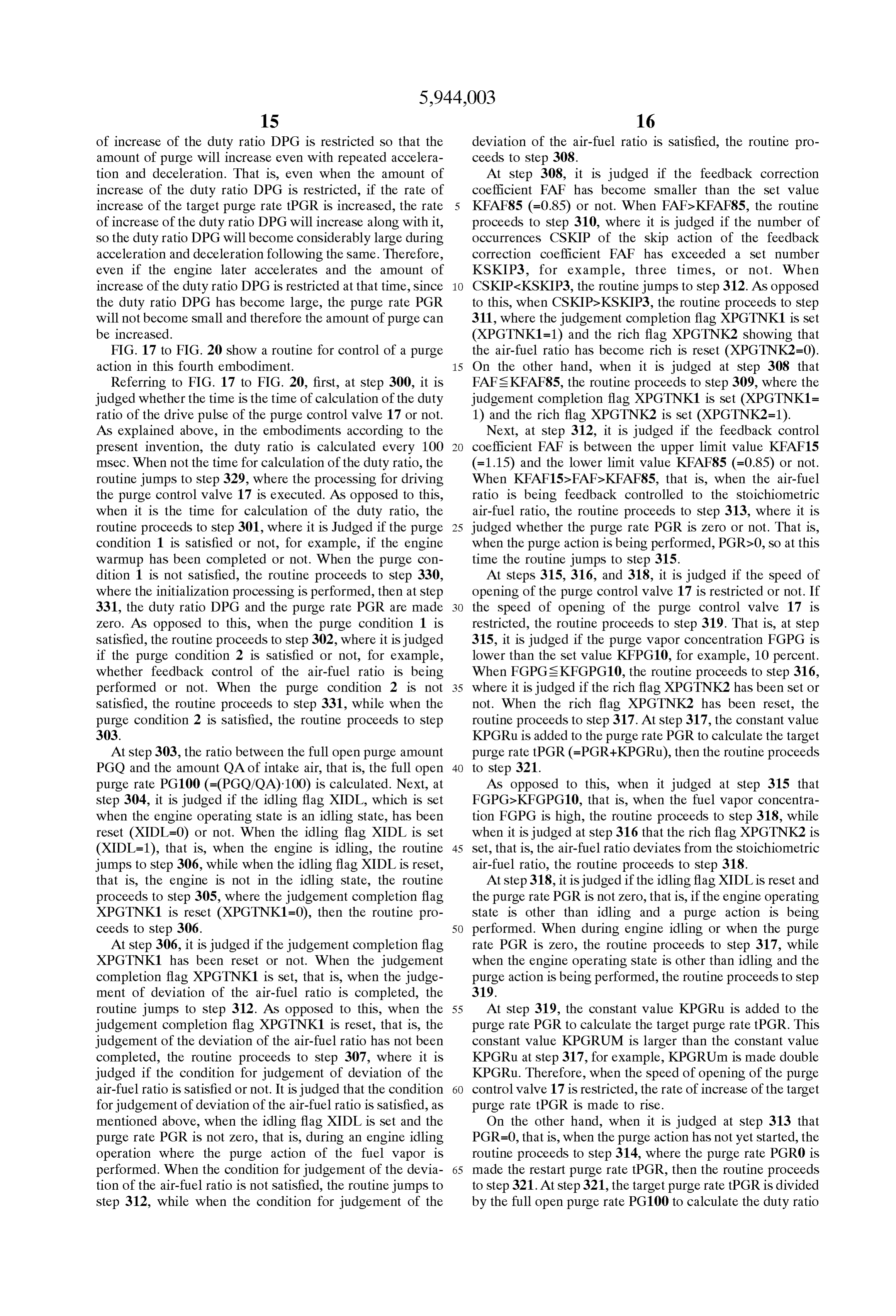
Page 30
DPG of the drive pulse of the purge control valve 17 tion calculating means deviates from an actual purge (=(tPGR/PG100)-100). Vapor concentration;
Next, at Step 322, it is judged if the purge vapor concen calculating means for calculating a target purge rate and tration FGPG is lower than the set value KFPGP10, for for determining a basic purge rate based on a prede example, 10 percent, or not. When FGPGs KFGPG10, the termined degree of opening of the purge control valve, routine proceeds to Step 323, where it is judged it the rich wherein the calculating means calculates an actual flag XPGTNK2 has been set or not. When the rich flag degree of opening of the purge control valve by divid XPGTNK2 has been reset, the routine proceeds to step 327. ing the target purge rate by the basic purge rate; and AS opposed to this, when it is judged at Step 322 that opening Speed restricting means for restricting a speed of FGPGDKFGPG10, that is, when the purge vapor concentra increase of the calculated degree of opening of the tion FGPG is high, the routine proceeds to step 324. Further, purge control valve to less than a predetermined Speed when it is judged at step 323 that the rich flag XPGTNK2 is when the calculated purge vapor concentration deviates Set, that is, the air-fuel ratio deviates from the Stoichiometric from the actual purge vapor concentration. air-fuel ratio, the routine proceeds to Step 324. 2. An evaporated fuel treatment device as Set forth in claim 1, wherein the deviation judgement means judges that
At step 324, it is judged if the condition for restriction of 15 deviation has occurred when the air-fuel ratio becomes rich the Speed of opening of the purge control valve 17 is at the time of engine idling.
satisfied or not. This condition is satisfied when the idling 3. An evaporated fuel treatment device as Set forth in flag XIDL is reset and the purge rate PGR is not zero, that claim 2, wherein the feedback control means controls the is, in an engine operation State other than idling when a air-fuel ratio to the target air-fuel ratio by correcting the purge action is being performed. When the condition for amount of Supplied fuel by a feedback correction coefficient restriction of the Speed of opening of the purge control valve which changes along with the air-fuel ratio detected by the 17 is not Satisfied, that is, during engine idling or when the air-fuel ratio detecting means, wherein the feedback correc purge rate PGR is zero, the routine jumps to step 327, while tion coefficient fluctuates about a predetermined reference when the condition for restriction of the Speed of opening of value when the air-fuel ratio is maintained at the target the purge control valve 17 is Satisfied, the routine proceeds 25 air-fuel ratio, and wherein the deviation judgement means to step 325. judges that deviation has occurred when the feedback cor At step 325, it is judged if the duty ratio DPG calculated rection coefficient becomes lower than a predetermined at Step 321 is larger than the value of the previously value at the time of engine idling.
calculated duty ratio DPG0 plus a constant value KDPGU 4. An evaporated fuel treatment device as Set forth in (DPG0+KDPGU) or not. When DPG&DPG0+KDPGU, the claim 3, wherein the purge vapor concentration calculating routine jumps to step 327, while when DPG2DPG0+ means increases the purge vapor concentration when the KDPGU, the routine proceeds to step 326 where (DPG0+ feedback correction coefficient becomes Smaller than the KDPGU) is made the duty ratio DPG. Next, the routine reference Value and decreases the purge Vapor concentration proceeds to step 327. when the feedback correction coefficient becomes larger At step 327, the full open rate PG100 is multiplied by the 35 than the reference value.
duty ratio DPG to calculate the actual purge rate PGR 5. An evaporated fuel treatment device as set forth in (=PG100-(DPG/100)). Next, at step 328, the duty ratio DPG claim 3, wherein the feedback correction coefficient is is made DPG0 and the purge rate PGR is made PGR0. Next, changed downward in a skipping fashion when the air-fuel at Step 329, processing is performed to drive the purge ratio changes from lean to rich, and wherein the feedback control valve 17 as shown in FIG. 10. 40 correction coefficient is changed upward in a skipping AS mentioned above, according to the present invention, fashion when the air-fuel ratio is changed from rich to lean, it is possible to prevent the air-fuel ratio from fluctuating by and wherein releasing means is provided for releasing the a large margin when performing a purge action of fuel vapor. restriction on the Speed of opening of the purge control valve While the invention has been described by reference to when the feedback correction coefficient remains at least as Specific embodiments chosen for purposes of illustration, it 45 high as the predetermined reference value during a period should be apparent that numerous modifications could be from a start of an idling operation to a time when the made thereto by those skilled in the art without departing feedback correction coefficient has been changed in a skip from the basic concept and Scope of the invention. ping fashion a predetermined number of times. I claim: 6. An evaporated fuel treatment device as Set forth in 1. An evaporated fuel treatment device for an engine 50 claim 1, wherein the correcting means corrects the amount provided with an intake passage, comprising: of fuel Supplied So that the amount of fuel Supplied becomes a purge control valve for controlling an amount of fuel Smaller as the purge vapor concentration increases. Vapor to be purged to the intake passage; 7. An evaporated fuel treatment device as set forth in air-fuel ratio detecting means for detecting the air-fuel 55 purge 1,control claim wherein the predetermined degree of opening of the valve is a fully open condition.
ratio;
feedback control means for feedback control of the air 8. An evaporated fuel treatment device as set forth in claim 7, wherein the opening Speed restricting means opens fuel ratio to make the air-fuel ratio a target air-fuel; the purge control valve by a speed of increase of the purge vapor concentration calculating means for calcu calculated amount of opening of the purge control valve lating a purge vapor concentration based on an amount 60 when the Speed of increase of the calculated amount of of fluctuation of the air-fuel ratio; opening is not more than a predetermined Speed and makes correcting means for correcting an amount of fuel to be the Speed of increase of the amount of opening of the purge Supplied to the engine based on the purge vapor con control valve a predetermined Speed when the Speed of centration calculated by the purge vapor concentration increase of the calculated amount of opening of the purge calculating means, 65 control valve is more than the predetermined speed. deviation judgement means for judging if the purge vapor 9. An evaporated fuel treatment device as set forth in concentration calculated by the purge vapor concentra claim 1, wherein judgement means is provided for judging
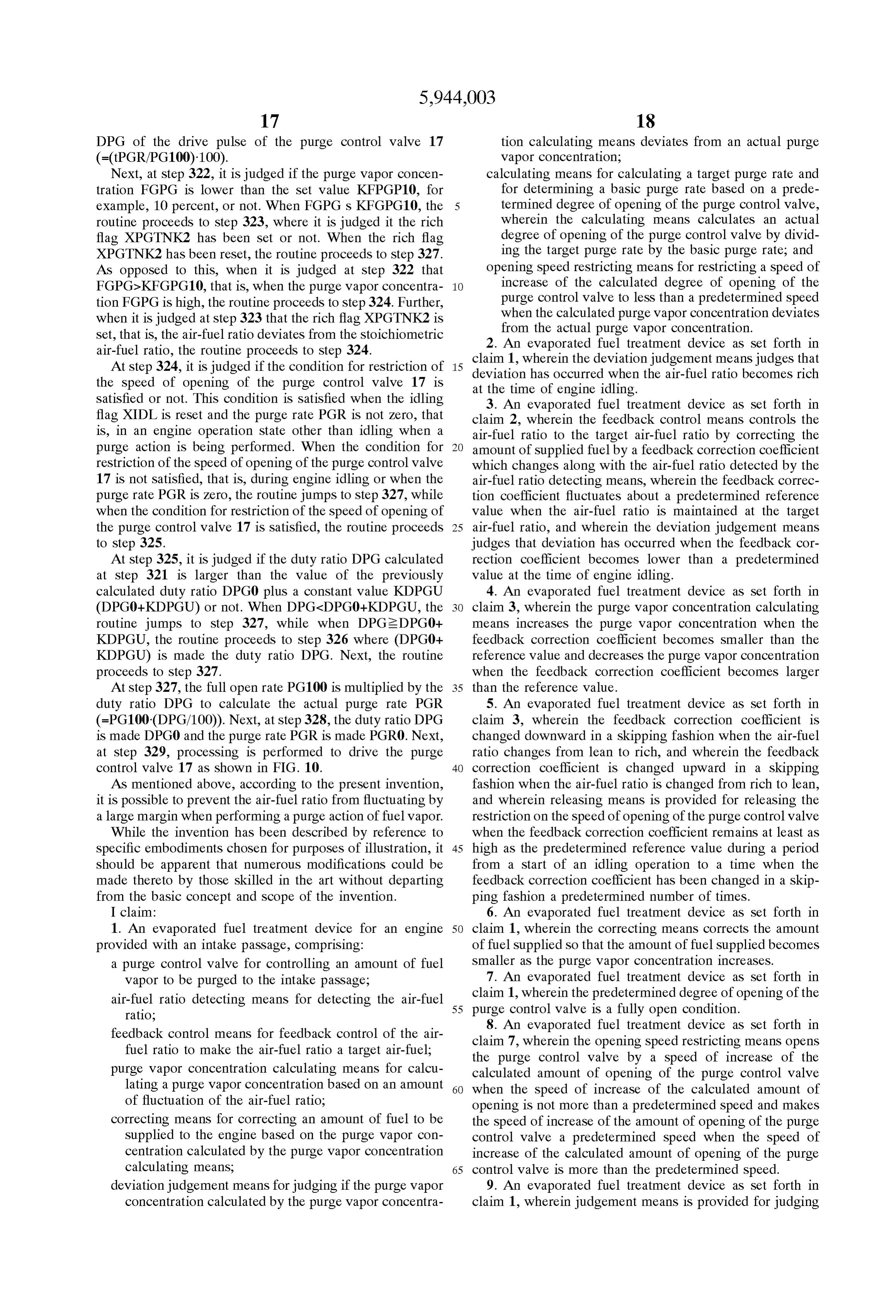
Page 31
if the purge vapor concentration calculated by the purge air-fuel ratio detecting means for detecting the air-fuel Vapor concentration calculating means has become higher ratio, than a predetermined concentration and wherein the opening feedback control means for feedback control of the air Speed restricting means restricts the Speed of opening of the fuel ratio to make the air-fuel ratio a target air-fuel; purge control valve to less than the predetermined Speed purge vapor concentration calculating means for calcu when the calculated purge vapor concentration becomes lating a purge vapor concentration based on an amount higher than the predetermined concentration.
10. An evaporated fuel treatment device as set forth in of fluctuation of the air-fuel ratio; claim 1, wherein Stability judgement means is provided for correcting means for correcting an amount of fuel to be judging if feedback control of the air-fuel ratio by the 1O Supplied to the engine based on the purge vapor con feedback control means is stable in an operating State other centration calculated by the purge vapor concentration than engine idling and wherein the deviation judgement calculating means, means judges that deviation has occurred when the engine deviation judgement means for judging if the purge vapor idles after the Stability judgement means judges that the concentration calculated by the purge vapor concentra feedback control of the air-fuel ratio is stable. 15 tion calculating means deviates from an actual purge 11. An evaporated fuel treatment device as Set forth in Vapor concentration, wherein the deviation judgement claim 10, wherein the feedback correction coefficient is means judges that deviation has occurred when the changed downward in a skipping fashion when the air-fuel air-fuel ratio becomes rich at the time of engine idling, ratio changes from lean to rich, the feedback correction and coefficient is changed upward in a skipping fashion when the opening Speed restricting means for restricting a speed of air-fuel ratio is changes from rich to lean, and the Stability opening of the purge control valve to less than a judgement means Judges that the feedback control of the predetermined speed when the calculated purge vapor air-fuel ratio is stable when the skip-like change of the concentration deviates from the actual purge vapor feedback correction coefficient has been performed a pre concentration.
determined time or more in a State other than engine idling. 25 18. An evaporated fuel treatment device as set forth in 12. An evaporated fuel treatment device as Set forth in claim 17, wherein the feedback control means controls the claim 1, wherein releasing means is provided for releasing air-fuel ratio to the target air-fuel ratio by correcting the the restriction of the Speed of opening of the purge control amount of Supplied fuel by a feedback correction coefficient Valve by the opening Speed restricting means directly after which changes along with the air-fuel ratio detected by the a purge action has Started. air-fuel ratio detecting means, wherein the feedback correc 13. An evaporated fuel treatment device as set forth in tion coefficient fluctuates about a predetermined reference claim 12, wherein releasing means is provided for releasing value when the air-fuel ratio is maintained at the target the restriction of the speed of opening of the purge control air-fuel ratio, and the deviation judgement means judges that Valve by the opening Speed restricting means in an operating deviation has occurred when the feedback correction coef State other than engine idling directly after a purge action has 35 ficient becomes lower than a predetermined value at the time Started. of engine idling.
14. An evaporated fuel treatment device as Set forth in 19. An evaporated fuel treatment device as set forth in claim 1, wherein the actual degree of opening of the purge claim 18, wherein the purge vapor concentration calculation control valve is increased by a predetermined ratio and means increases the purge vapor concentration when the wherein the predetermined ratio is increased when the Speed 40 feedback correction coefficient becomes Smaller than the of opening of the purge control valve is restricted to less than reference value and decreases the purge vapor concentration a predetermined speed by the opening Speed restricting when the feedback correction coefficient becomes larger CS. than the reference value.
15. An evaporated fuel treatment device as set forth in 20. An evaporated fuel treatment device as set forth in claim 14, wherein releasing means is provided for releasing 45 claim 18, wherein the feedback correction coefficient is the restriction of the Speed of opening of the purge control changed downward in a skipping fashion when the air-fuel Valve by the opening Speed restricting means in an operating ratio changes from lean to rich, and wherein the feedback State other than engine idling. correction coefficient is changed upward in a skipping 16. An evaporated fuel treatment device as set forth in fashion when the air-fuel ratio is changes from rich to lean, claim 15, wherein releasing means is provided for releasing 50 and wherein releasing means is provided for releasing the the restriction of the Speed of opening of the purge control restriction on the Speed of opening of the purge control valve Valve by the opening Speed restricting means in an operating when the feedback correction coefficient remains at least as State other than engine idling directly after a purge action has high as the predetermined reference value during a period Started. from a start of an idling operation to a time when the 17. An evaporated fuel treatment device for an engine 55 feedback correction coefficient has been changed in a skip provided with an intake passage, comprising: ping fashion a predetermined number of times. a purge control valve for controlling an amount of fuel
Vapor to be purged to the intake passage; k k k k k
Page 32
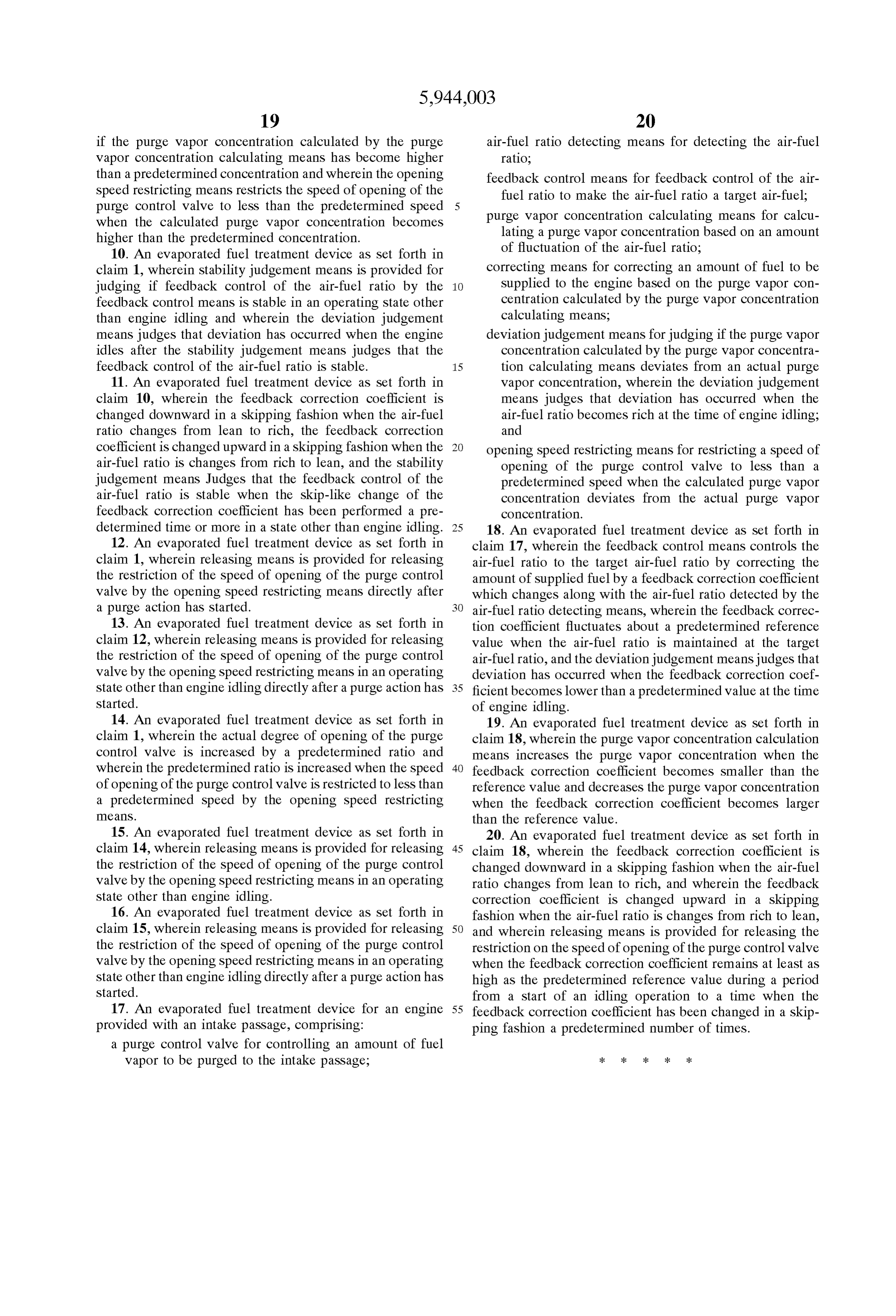
UNITED STATES PATENT ANDTRADEMARK OFFICE
CERTIFICATE OF CORRECTION
PATENT NO. : 5,944,003 Page 1 of 2
NVENTOR(S) : Akinori OSANAI it is certified that error appears in the above-identified patent and that said Letters Patent is hereby Corrected as shown below:
Column 5, line 39, change "AFPGA" to --AFPGA--.
Column 7 line 14, change "Judged" to --judged--.
Column 7, line 25, delete "1 0".
Column 9 line 43, change "LTPG" to -- t TPG--.
Column l l line 43, change "embodiment; it to
Column 13, line change " (= (tPGR/PG1 OO)-100) to
Column 15, line change "Judged" to --judged--. Column 16, 1 ine change "CSKIP7 KSKIP3, it to
Column l6, line 57, change "KPGRUM" to --KPGRUm--.
Column l7, line 5, change "FGPG sit to --FGPG 4--.
Page 33
UNITED STATES PATENT ANDTRADEMARK OFFICE
CERTIFICATE OF CORRECTION
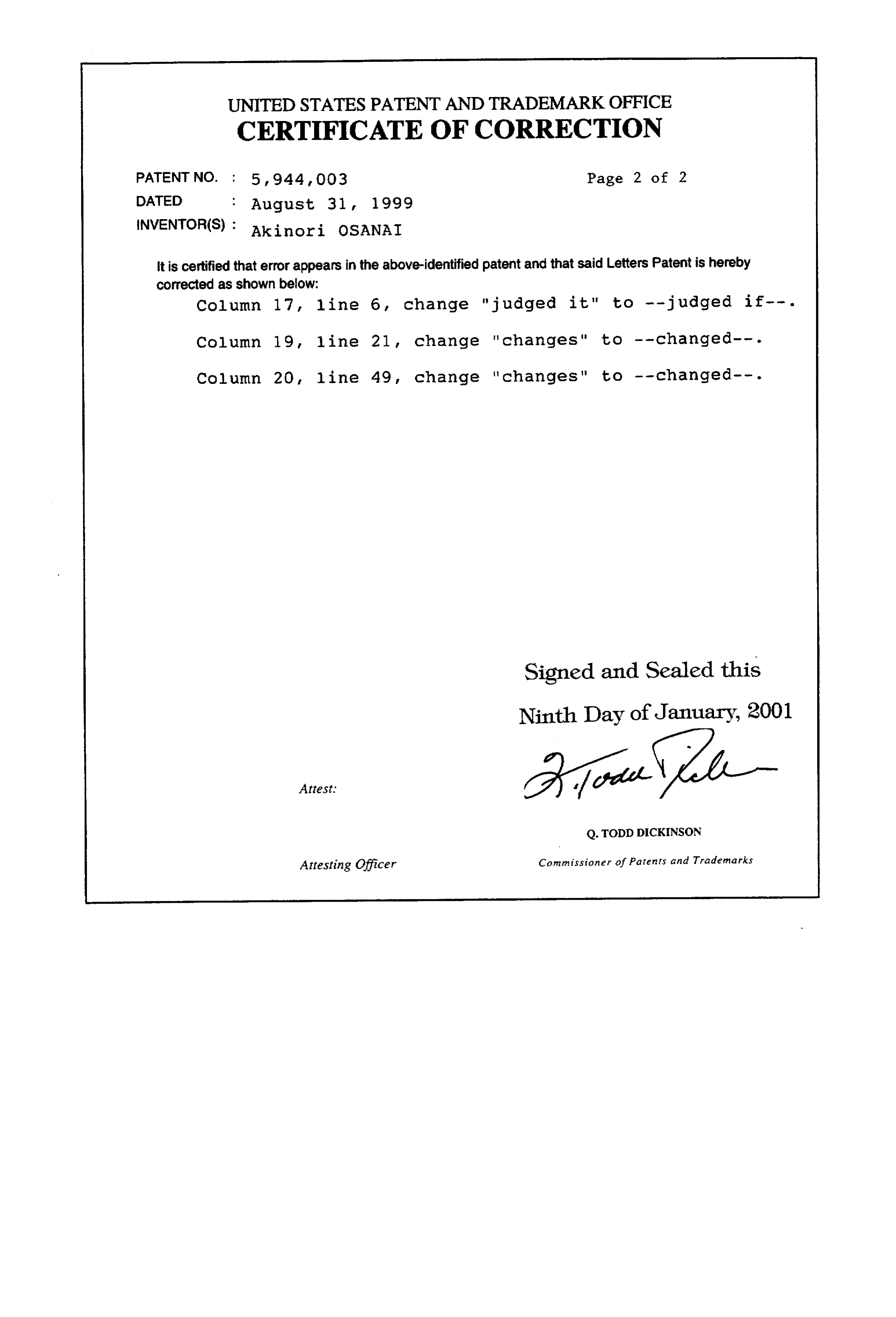
PATENT NO. : 5,944 003 Page 2 of 2
NVENTOR(S) : Akinori osANAI it is certified that error appears in the above-identified patent and that said Letters Patent is hereby corrected as shown below:
Column 17, line 6, change "judged it" to --judged if--.
Column 19, line 21, change "changes" to -- changed--.
Column 20, line 49, change "changes" to -- changed--.
Signed and Sealed this
Ninth Day of January, 2001
Q.TODD DICKINSON
Attesting Officer Commissioner of Patents and Trademarks
Provenance
- Collection
- Cited prior art
- Original PDF
- patentimages.storage.googleapis.com →
- Filed
- 1997-08-07
- Pages
- 33
- Method
- pdftotext (the PDF's own text layer) + pdftoppm 300dpi page scans
- Source
- Google Patents bibliographic record
- Granted
- 1999-08-31
- Inventors
- Akinori Osanai; Toyota Motor Corp
- Transcribed from
- patentimages.storage.googleapis.com →