patent · US4436373
Solar reflector panel
13 March 1984
Page 1 — bibliographic record
United States Patent (19) 11) 4,436,373 Kirsch 45) Mar. 13, 1984 54 SOLAR REFLECTOR PANEL 3,985,429 10/1976 Fleischer ............................. 350/288 75) Inventor: Paul A. Kirsch, Bensalem, Pa. FOREIGN PATENT DOCUMENTS 73 Assignee: The Budd Company, Troy, Mich. 749441 11/1944 Fed. Rep. of Germany ...... 350/296 (21) Appl. No.: 277,097 Primary Examiner-Jon W. Henry 22 Filed: Jun. 25, 1981 Attorney, Agent, or Firm-Edward M. Farrell; Herman Foster; Thomas I. Davenport
52) U.S. Cl. .................................... 350/296; 350/590; 57 ABSTRACT
58) Field of Search ............... 350/293, 296, 288, 320, A solar reflector panel includes a glass reflector element 350/590; 264/1.9, 1.2 held by a thermoset plastic backing. The backing is
molded around the reflector element to provide lips to lock the element in place on the backing.
3,427,095 2/1969 Dykema et al. .................... 350/288 1 Claim, 5 Drawing Figures
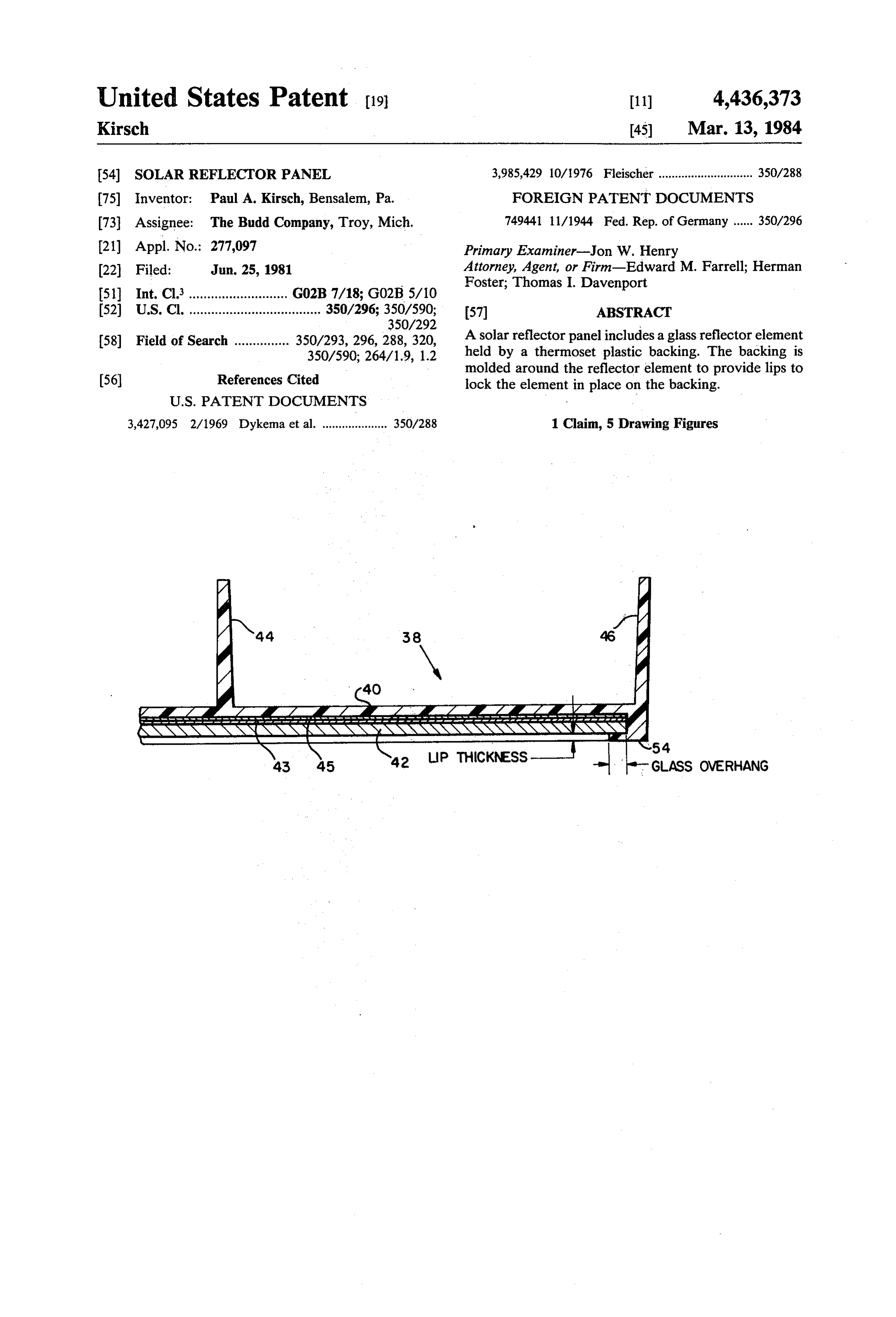
NSSSSSSSSSSSSSSSSSSNNya a2 LP THICKNESS - GLASS OVERHANG
Page 2
Drawing sheet — no readable text.
Page 3
Drawing sheet — no readable text.
Page 4
Drawing sheet — no readable text.
Page 5
barrier to the reflective coating necessary for long term
SOLAR REFLECTOR PANEL outdoor use.
Other objects and advantages of the present invention
BACKGROUND OF THE INVENTON will be apparent and suggest themselves to those skilled Solar reflector panels for reflecting energy from the 5 in the art, from a reading of the following specification sun to a receiver are well known. Generally, an array of and claims, taken in conjunction with the accompany aligned reflector panels are mounted on a strongback ing drawings.
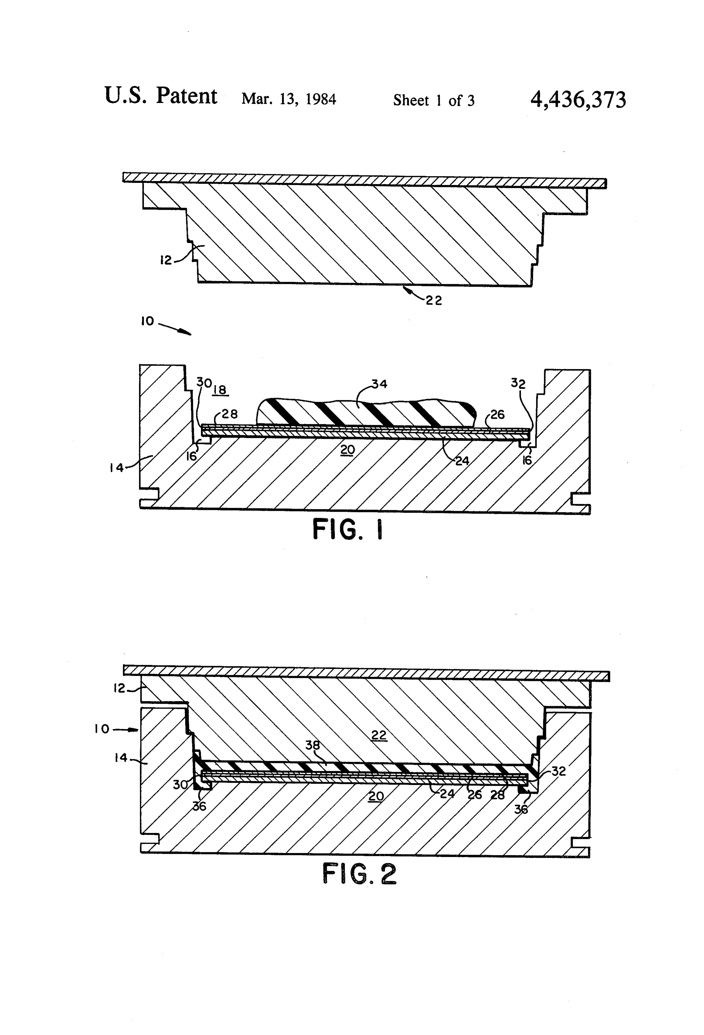
and are rotatable to permit them to receive maximum energy from the sun. The energy reflected to the re 10 BRIEF DESCRIPTION OF THE DRAWINGS ceiver is generally used to heat a liquid, such as oil or FIG. 1 is a cross-sectional view, before pressure ap liquid which is circulated to transfer the heat to a home plication, illustrating a step in a compression molding or other utilization means. process for making a solar reflector panel, in accor Solar reflector panels can be made of parabolic mir dance with the present invention;
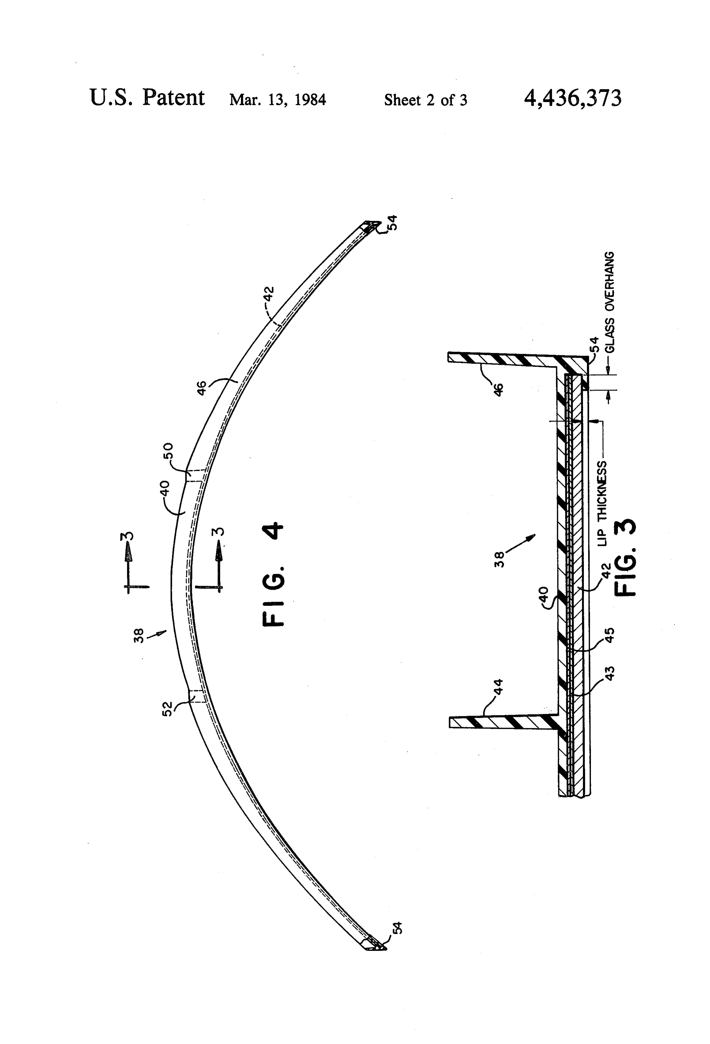
ror elements which are secured to and supported by FIG. 2 is a cross-sectional view, during pressure ap backing members. These backing members are gener 15 plication, illustrating another step in a compression ally made of solid frame material and could be made of molding process following the step illustrated in FIG. 1; metal stampings of a type described in a copending FIG. 3 is a partial cross-sectional view taken along application entitled "Panel for Solar Heating Systems', lines 3-3 of a typical solar reflector panel illustrated in Ser. No. 185,360, filed Sept. 8, 1980, and assigned to the 20 FIG. 4;
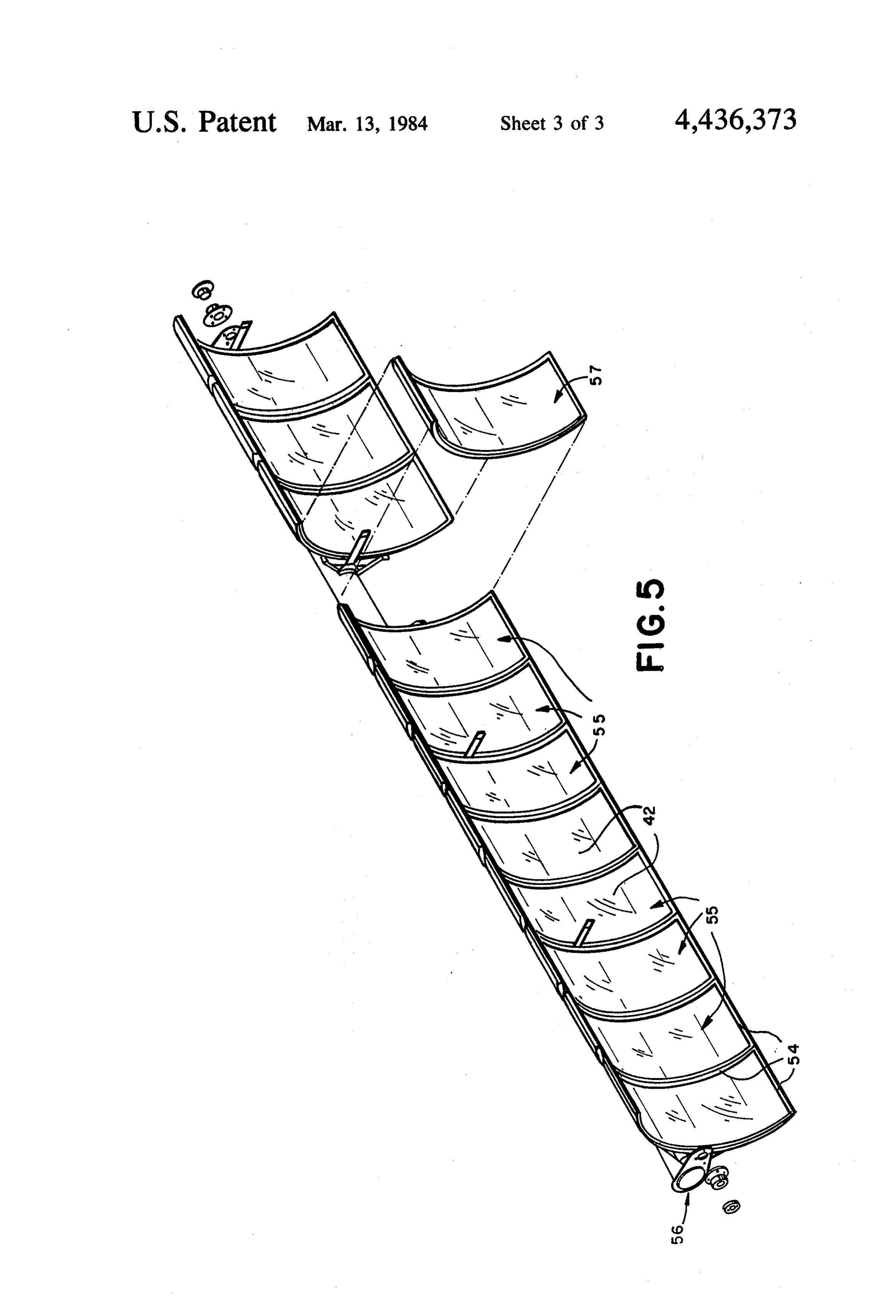
same assignee as the present invention. FIG. 4 is a parabolic solar reflector panel, in 2CCOs While such solar reflector panels utilizing frame dance with the present invention; and metal backings are generally acceptable, it is often desir FIG. 5 illustrates an array of solar reflector panels of able to provide panel reflectors which minimize the the type utilizing the present invention. number of parts required while at the same time, pro vide adequate locking and protection of the reflector 25 elements to the backings. Providing locking and protec
DETAILED DESCRIPTION OF THE
PREFERRED EMBODIMENTS
tion of the reflector elements with integral backing units Referring to FIGS. 1 and 2, there will first be de of high resistance and durability is also desirable in scribed a molding process which is applicable to form many cases. This is especially true since such reflector 30 ing a solar reflector panel to be discussed and described elements are generally exposed to severe environmental in detail in subsequent FIGS. 3, 4 and 5. It is understood conditions including snow and winds up to 90 m.p.h., that the term solar reflector panel includes the complete
panel, such as the glass with a silver reflective coating,
OBJECTS OF THE INVENTION for example, protective coating for the reflective back It is an object of this invention to provide improved 35 ing and a solid backing element or frame for holding the glass. A heated mold 10 comprises a first upper male solar panel reflectors and methods for making them.
It is a further object of this invention to provide im and second lower female mold pieces 12 and 14. These pieces 12 and 14 each comprise half of the mold and are proved solar panel reflectors, and methods for making them, having improved molded backings. W movably disposed with respect to each other, for exam It is still a further object of this invention to provide ple, the piece 12 is adapted to be lowered toward the improved solar panel reflectors, and methods for mak piece 14. The mold pieces 12 and 14 may be generally ing them, having molded backings with improved rectangular in shape and in the embodiment illustrated means for locking the reflectors thereto. are designed to co-mold fiber glass reinforced plastic It is still a further object of this invention to provide material with a rectangular glass sheet suitably coated. improved solar panel reflectors, and methods for make 45 The lower piece 14 includes a groove 16 toward the ing them, having improved molded backings which bottom of the cavity 18 of the piece 14, which extends protect the reflective elements of the panel reflectors. around the inner periphery thereof. The central part 20 It is still a further object of this invention to provide of the mold piece 14 is shaped to receive a reflector an improved backing for reflective elements which is element, as will be described, The portion 20 may be capable of withstanding severe loading conditions and 50 parabolic or any suitable shape dependent upon the adapted for long term outdoor use. shape of the reflector element to be received thereon.
BRIEF SUMMARY OF THE INVENTION
The upper piece 12 includes a male portion 22 which is adapted to be moved into the cavity 18. The portion
In accordance with the present invention, methods 22, except for structural considerations such as ribs, as and means are provided to produce an improved solar 55 illustrated in FIG. 3, is generally shaped to the same reflector panel. A fiber reinforced thermoset piece is contour as the cavity 18.
molded to hold a glass sheet which has a suitable reflec The mold 10 is utilized in conventional compression tive and protective coating. During the molding pro molding processes wherein an upper half of a mold is cess, molding compound material is placed on the pro lowered into the lower half to form a molded piece. tective coating on the rear surface of the glass sheet and Such processes are well known and will not be de the material, under pressure and temperature, extends scribed in detail except to say that such molding pro around the sides of the sheet to provide a lip or extend cesses involve controlled heating of the mold pieces and ing portion to mechanically lock the reflective sheet in selectively controlled relative movements of the mold an accurate contour after the molding material has pieces. The various means for selectively moving the cured. The lip of the molding compound keeps the 65 piece 12 towards the piece 14 are well known in the reflective sheet and molding compound together and compression molding art.
prevents the sheet from popping loose under severe A rectangular glass sheet 24 is clear on its front sur loading conditions and also provides an environmental face and is coated on its rear surface in a conventional
Page 6
manner, for example, by a reflective coating 26, such as illustrated in FIGS. 1 and 2. The backing 40 includes a a coating of silver, on one side and a protective coating pair of ribs 44 and 46 which are added to the backing for 28, such as paint, on the back of the reflective surface strength and stiffness. Any number of ribs may be used 26. The thicknesses of the coatings on the glass are 5 dependent on the backing design. The cavities for form illustrated"greatly exaggerated. The glass sheet 24 with ing the ribs would normally be built into the mold its reflective coating comprises a conventional mirror pieces, which mold the backing. The cavities for mold like element used to reflect energy which is directed ing the ribs were not illustrated in FIGS. 1 and 2. thereon, for example, energy received from the solar Referring to FIG. 4, the solar panel 38 is illustrated rays. with attachment points provided by elements 50 and 52. The glass sheet. 24 comprises four edges, with only 10 The backing 40 receives a glass sheet 42 which is held the side edges 30 and 32 being-illustrated. The mold 10 by the lip 52 forming part of the backing. The glass is designed to receive the glass sheet 24 in the manner sheet 42 includes a silver coating 43 and protective illustrated so that the four edges of the glass sheet ex coating 45. The solar panel illustrated is parabolic in tend beyond the portion 20 partly over the groove 16 shape with the molded material being around the glass extending around the periphery of the lower mold piece 15 and the lip 54 being disposed around the periphery of the sheet of glass 42. The back-up material holds the
Molding compound 34, suitable for producing high glass with reflective and protective coatings in an accu strength fiberglass reinforced thermoset plastic backing rate parabolic shape with the help of the molded lip of or framing for the glass, is placed on the protective the compound molding material around the periphery surface.28 which is on the silver coating 26 of the glass 20 of the glass.
sheet 24. The heated male mold or top piece 12, is then Some combinations found acceptable in experiments lowered toward the heated female mold half piece 14. have involved the following dimensions: 0.060 inchlip The mold halves, which are coiled for steam or oil thickness with 0.125 inch glass overhang; 0.060 inch lip heating, not illustrated, are generally mounted in a hy thickness with 0.25 inch glass overhang; 0.125 inch lip draulic-press, also not illustrated. As mentioned, the 25 thickness with 0.250 inch glass overhang; and 0.040 inch lower mold piece 14 is grooved about its periphery to lip thickness with 0.250 inch glass overhang. The num provide: the groove 16. The various sizes of the grooves ber of sides providing the lip of molding compound can and glass sheets are dimensioned to provide the correct vary from one to all four. A preferred embodiment of overhang of its four edges, such as edges 30 and 32, to the invention involves a lip extending on the four front allow the sheet of glass 24 to be placed in the mold in 30 edges of the glass sheet. All of the combinations men the proper position to permit the molding compound 34 tioned were successful in that a clearly defined lip of to flow under the four edges into contact with the outer molding compound was molded under the glass surface edge-portions of the front surface of the glass 24. . . . without breaking the glass. . . . . . . FIG. 2 illustrates the mold piece 12 in an operative Referring particularly to FIG. 5, a plurality of panels down position with respect to the piece 14. In this posi 35 55, which may have a backing with ribsections of the tion, the molding compound 34 is spread out about the type illustrated in FIG. 4, are shown. The panels are entire protective surface 28 which is coated to the back mounted upon a strongback assembly 56 which may be or top surface of the glass 24, which also includes the connected to means to move the panels in a direction to reflective mirror coating 26. As illustrated, the material receive maximum energy from the sun. A lip of molded 34 extends around the four side edges of the glass into material surrounds the periphery of each of the panels the groove 16 to provide a lip 36 about the front periph 55. A panel 57 is illustrated away from a strongback to ery of the glass 24. The molding compound 34 flows show some of the details of the solar panel with the around and under the glass to provide mechanical lock reflective glass material within the molded material. ing for the glass sheet 24. The thermoset material 34 is Various collector elements generally used with a system then permitted to cure to provide a hard integral back 45 such as illustrated in FIG. 5 are not illustrated because ing for the glass sheet 24. The hardened compound they do not form part of the invention. material lip provides a strong mechanical locking means The present invention has provided a solar panel in which holds the glass sheet in an accurate contour nec which a single structure is used as the backing for the essary for efficient solar panel reflectors. The lip 36 of reflector elements. No bonding of the reflector element the molding compound also gives an added safety fea 50 to the backing is required. However, in some cases, an ture in keeping the glass 24 and molding compound adhesive may be used on the rear surface of the glass to together, preventing the glass from popping loose under provide bonding of the glass to the back-up material. severe loading conditions which could possibly cause The material of the back-up material is made relatively injury to by-standers. The lip 36 of the molding com strong and capable of withstanding severe environmen pound also provides an environmental barrier necessary 55 tal conditions.
for long term outdoor use of solar panel reflectors. The glass material used for the sheets of glass gener The molding steps illustrated in FIGS. 1 and 2 illus ally comprises chemically strengthened glass. The basic trate the general arrangement for the process for pro problem involves, providing the lip around the glass ducing a solar panel embodying the present invention. surface during the molding process without breaking It is apparent that the two mold pieces may be of any 60 the glass. Consequently, the relationship between the configuration designed to accommodate the particular overhang of the glass within the mold and the lip design of the back up material to be used for the glass formed must be kept with certain dimensions, some sheet. s - - examples of which have been discussed in connections Referring to FIG. 3, a portion of a solar panel 38 with FIG. 4. . . is . . . includes the thermoset material in a hardened state 65 While glass has been mentioned throughout the speci illustrated as being a backing 40. The backing 40 is fication, it is apparent that other transparent materials adapted to hold the glass sheet 42 which includes reflec which transmit light may be used. Such materials must tive surface 43 and protective coating 45 similar to those be capable of withstanding the temperature and pres
Page 7
sure found in conventional compression molding pro (e) said piece extending around the four side edges of said glass sheet and extending partly across the
What is claimed is: front surface thereof to provide a lip portion about 1. A parabolic solar reflector panel for focusing en 5 the periphery of said glass sheet to mechanically ergy received from the sun comprising: lock said sheet to said piece; (a) a glass sheet with four side edges and having front (f) said lip portion extending from 0.25" to 0.125" and rear surfaces; over the front surface of said glass sheet and having (b) said rear surface of said glass sheet having a reflec a thickness between 0.040' to 0.125'; tive coating thereon; (g) attachment elements disposed on said solar panel; (c) said reflective coating having a protective coating 10 (h) a strongback assembly;
thereon;
(i) means including said attachment elements to con nect said solar reflector panel to said strongback;
(d) an integral fiberglass reinforced thermoset piece and having a plurality of rib portions secured to said (j) said strongback assembly being movable to move protective coating to provide a backing of uniform 15 said reflector panel in a direction to receive maxi thickness for said glass sheet with said reflective mum energy from the sun.s and protective coatings; sk e
Provenance
- Collection
- Cited prior art
- Original PDF
- patentimages.storage.googleapis.com →
- Filed
- 1981-06-25
- Pages
- 7
- Method
- pdftotext (the PDF's own text layer) + pdftoppm 300dpi page scans
- Source
- Google Patents bibliographic record
- Granted
- 1984-03-13
- Inventors
- Paul A. Kirsch; Budd Co
- Transcribed from
- patentimages.storage.googleapis.com →