patent · US2385699
Fuel ignition system
25 September 1945
Page 1
Drawing sheet — no readable text.
Page 2
Patented Sept. 25, 1945 2,385,699
UNITED STATES PATENT of FICE
FUE, GNON SYSTEM
Wernie A. Fox, Detroit, Mich.
Application September 8, 1941, Serial No. 40,018
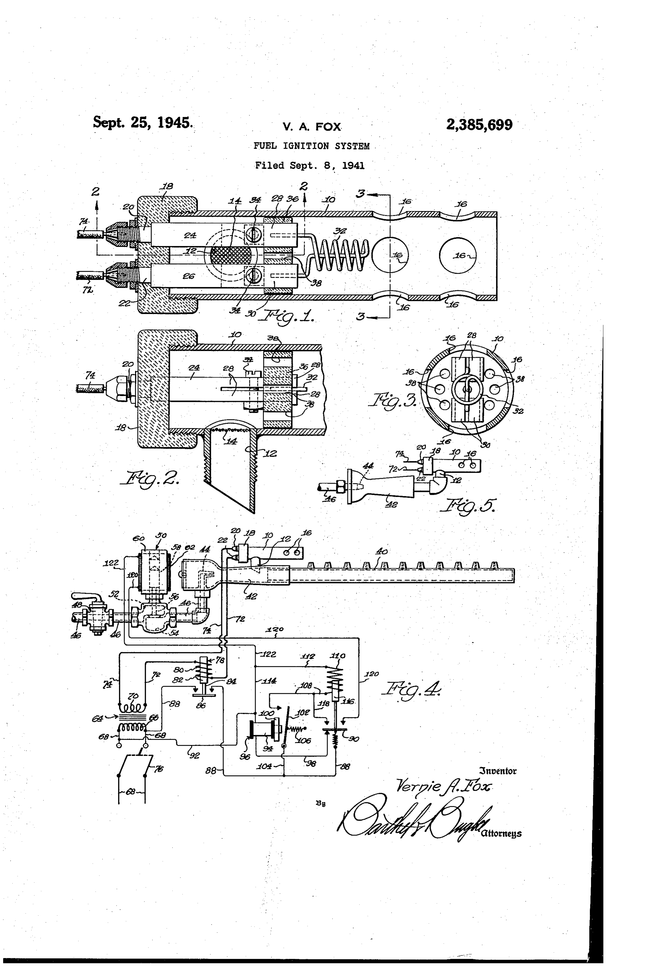
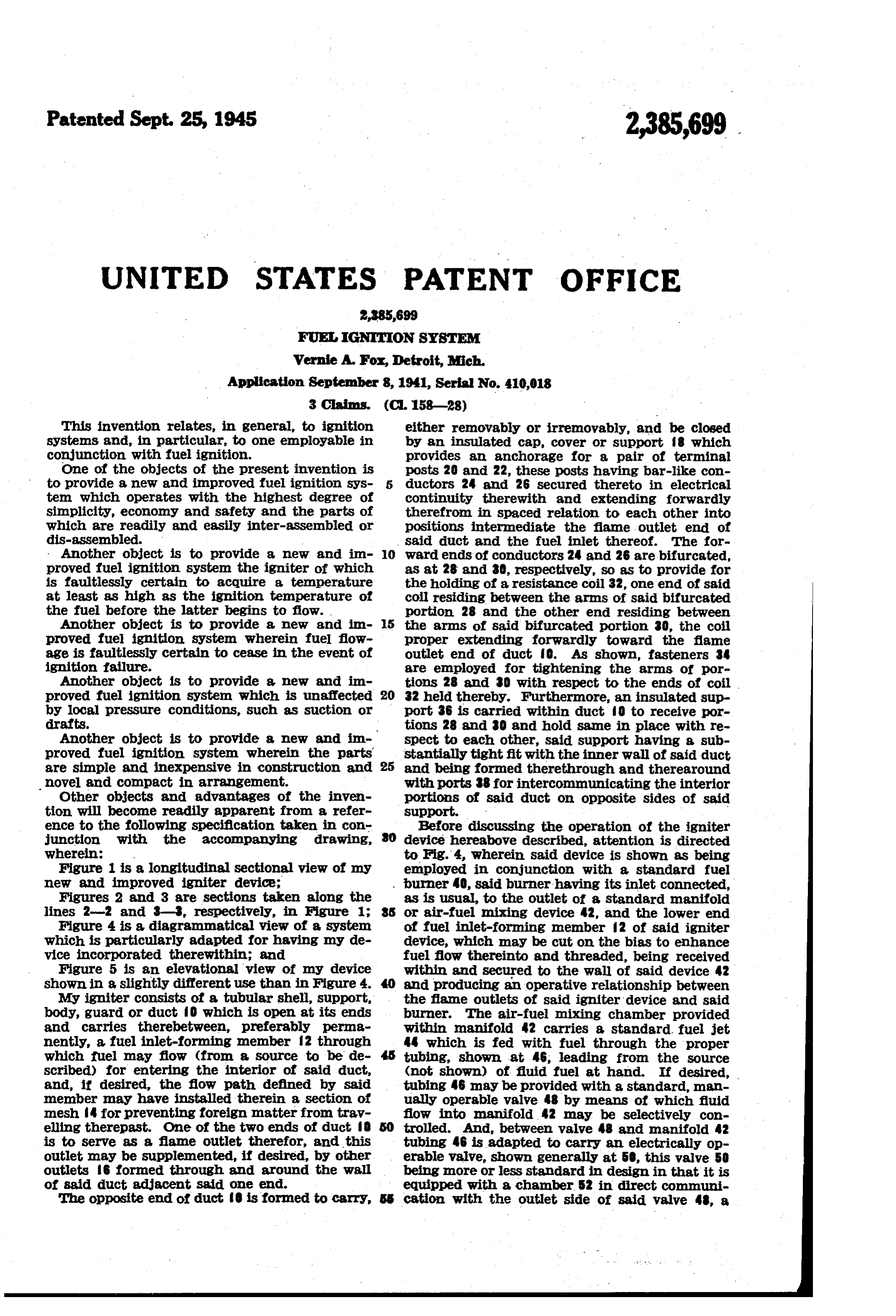
This invention relates, in general, to ignition either removably or irremovably, and be closed systems and, in particular, to One employable in by an insulated cap, cover or support which conjunction with fuel ignition. provides an anchorage for a pair of terminal One of the objects of the present invention is posts 20 and 22, these posts having bar-like con to provide a new and improved fuel ignition sys ductors 24 and 26 secured thereto in electrical tem which operates with the highest degree of continuity therewith and extending forwardly simplicity, economy and safety and the parts of therefrom in spaced relation to each other into which are readily and easily inter-assembled or positions intermediate the fame outlet end of dis-assembled. said dict and the fuel inlet thereof. the for Another object is to provide a new and in O ward ends of conductors 24 and 26 are bifurcated, proved fuel ignition system the igniter of which as at 28 and 30, respectively, so as to provide for is faultlessly certain to acquire a temperature the holding of a resistance coil 32, one end of said at least as high as the ignition temperature of coil residing between the arms of said bifurcated the fuel before the latter begins to flow. portion 28 and the other end residing between Another object is to provide a new and in 5 the arms of said bifurcated portion 30, the coil proved fuel ignition system wherein fuel flow proper extending forwardly toward the flame age is faultlessly certain to cease in the event ofoutlet end of duct O. As shown, fasteners 34 ignition failure. are employed for tightening the arms of por Another object is to provide a new and in tions 28 and 30 with respect to the ends of coil proved fuel ignition system which is unaffected 20 32 held thereby. Furthermore, an insulated sup by local pressure conditions, such as suction or port 36 is carried within duct ?o to receive por drafts. tions 28 and 30 and hold same in place with re Another object is to provide a new and im spect to each other, said support having a sub proved fuel ignition system wherein the parts stantially tight fit with the inner wall of said duct are simple and inexpensive in construction and 25 and being formed therethrough and therearound novel and compact in arrangement. with ports 38 for intercommunicating the interior Other objects and advantages of the inven portions of said duct on opposite sides of said tion will become readily apparent from a refer support.
ence to the following specification taken in cont Before discussing the operation of the igniter junction with the accompanying drawing, O device hereabove described, attention is directed wherein: to Fig. 4, wherein said device is shown as being Figure 1 is a longitudinal sectional view of my employed in conjunction with a standard fuel new and improved igniter device; burner 40, said burner having its inlet connected, Figures 2 and 3 are sections taken along the as is usual, to the Outlet of a standard manifold lines 2-2 and 8-8, respectively, in Figure 1: or air-fuel mixing device 42, and the lower end Figure 4 is a diagrammatical view of a system of fuel inlet-forming member 2 of said igniter which is particularly adapted for having my de device, which may be cut on the bias to enhance vice incorporated therewithin; and fuel flow thereinto and threaded, being received Figure 5 is an elevational view of my device within and secured to the wall of said device 42 shown in a slightly different use than in Figure 4. and producing an operative relationship between My igniter consists of a tubular shell, support, the fame outlets of said igniter device and said body, guard or duct ?o which is open at its ends burner. The air-fuel mixing chamber provided and carries therebetween, preferably perma within manifold 42 carries a standard fuel jet nently, a fuel inlet-forming member 2 through 44 which is fed with fuel through the proper which fuel may flow (from a source to be de tubing, shown at 46, leading from the source scribed) for entering the interior of said duct, (not shown) of fluid fuel at hand. If desired, and, if desired, the flow path defined by said tubing 46 may be provided with a standard, man member may have installed therein a section of ually operable valve 48 by means of which fluid mesh 4 for preventing foreign matter from trav flow into manifold 42 may be selectively con elling therepast. One of the two ends of duct trolled. And, between valve 48 and manifold 42 is to serve as a flame outlet therefor, and this tubing 46 is adapted to carry an electrically op outlet may be supplemented, if desired, by other erable valve, shown generally at 50, this waive 50 outlets 6 formed through and around the wall being more or less standard in design in that it is of said duct adjacent Said one end. equipped with a chamber 52 in direct communi The opposite end of duct 0 is formed to carry, SS cation with the outlet side of said valve 48, a
Page 3
chamber 54 in direct communication with said closing of series circuit 70-72-80-72-32 74-70, is employed for the purpose of bringing manifold, a valve member 56 operable for cont relay 96 into play, the effect of which is to be trolling fuel flow from said chamber 52 into said described presently. This relay is of the delayed chamber 54, a core 58 secured to said valve men ber 56 for movement therewith, a magnet body action type (the reason, as will soon be seen, being so receiving said core and energizable to move to provide a time interval between the energizing of coil 32 and the opening of valve 50) and is of same, and a coil 62 operable for energizing said standard magnet. Incidentally, the normal position of is operable construction, having a magnet OO which valve member 56 is that whereat chambers 52 O the initiationat ofa predetermined period following energy flow through coil 94 for and 54 are cut off from each other, this condi tion existing during electrical inactivity of moving a spring-held switch element 02 into play coil 62. to close a circuit which will soon be described. still referring to Figure 4, it will be seen that Switch element 02 has one of its ends per I provide a transformer, generally indicated at manently connected to an end of a lead 04 con 64, which is of the step-down type because I in 5 nected to lead 88 between switch elements 86 and tend using a current of relatively low voltage for 90, and the other end of said element O2 is energizing the coil 32 of my igniter device, this adapted, upon effective energization of magnet transformer having a primary 66 connected across f00, to be drawn, against the force of a spring a service line 68 and a secondary 70 connected by O6, into connection with one end of a lead 08 means of leads 72 and 74 to the posts 22 and 20 20 the other end of which is connected to one side of said device. Line 68 preferably has a Switch of a solenoid coil fo. The other side of coil 0 Ts arranged therein whereby the energization of is connected to lead 92, which interconnects One primary 66 may be controlled, and it is to be side of primary 66 and One side of coil 94, by noted that said switch is the sole controlling means of leads 2 and 4. • means for coil 32; in other words, regardless of 25 When magnet OO becomes effective to cause what happens in the system described herebelow, interconnection of leads 4 and 8 by means when switch 76 is closed, coil 32 is energized, of switch element O2, coil to becomes energized and, when switch 76 is open, coil 32 is de-ener and actuates a core 6 to which SWitch element gized. And, when coil 32 is energized by the 90 is fixedly connected, and this element 90, to closing of switch 76, the fuel-air mixture passing 30 which lead 88 is permanently but resiliently con through member 2, into duct 0, through ports nected, is drawn out of connection with lead 98 38, and into contact with said coil, Will become and into simultaneous connection. With an end of ignited and the resulting flame will be emitted each of two other leads 8 and 20, the other through the outlet end and other outlets 6 of end of said lead 8 being connected to said lead said duct, there to ignite the fuel-air mixture 35 08 between said switch element 02 and said being emitted from burner 40 and thus serve for coil O, and the other end of Said lead 20 being the most part as a pilot burner. connected to one side of coil 62 of electrically A relay, generally indicated at 78, has its coil operable valve 50. The other side of coil 62 is 80 connected in the secondary circuit in Series connected to primary 66 by means of a lead 22 with secondary 70 and coil 32, namely, in the lead 40 which is connected to leads 2 and 4. 72 which interconnects one side of said Secondary In short, when switch 76 is closed, igniter ele and one side of said coil 32, said relay having, ment 32 becomes energized and, in addition, in addition to said coil 80, a magnet 82 which Switch 86 is caused to close the circuit 66-88 is energizable responsive to energization of said 45 86-88 -90-98-94-92-66 which includes coil coil 80, a core 84 which is movable responsive to 94. Upon the expiration thereafter of a pre energization of said magnet, and a Switch element determined period (which is, of course, sufficient 86 which is carried by Said core for movement to permit the temperature of coil 32 to reach a therewith. Switch element 86, upon energiza value at least equal to the ignition tempera tion of coil 80 responsive to the closing of switch 50 ture of the fuel-air mixture which is to pass 6 and the resulting energization of Secondary through duct ?o from manifold 42 upon the open TO, is adapted to close a break existing during de ing of valve 50), magnet OO becomes capable energization of said coil in a lead 88 which is con of drawing switch 02 into contact with lead to8 nected at one of its ends to one side of primary 66 and thereby place coil in readiness for ener and at the other of its ends to another switch 55 gization and the job of moving switch 90 from element 90 (which is to be described presently). its position of contact with lead 98 into posi One end of another lead 92 is connected to the tion of contact with leads 8 and 20. The opposite side of primary 66, and the opposite end circuit which is closed under the influence of of this lead is connected to one side of the coil magnet OO is 66-88-86-88-04-02-08 9 of a relay, generally indicated at 96 and to 60 O-2-4-92-66 and may be termed an be described presently, the Opposite side of Said "initiating' circuit for coil 0, for.it is reopened coil being connected by means of a lead 98 to the immediately upon the breakage of the contact aforementioned switch element 90. It is seen, between Switch 90 and lead 98 which is influenced therefore, that the closing of switch 76 energizes by the energization of said coil. However, the coils 80 and 32 and that the energization of Said energization of coil ff0 continues after the re coil 80 simultaneously effectuates the closing of 65 opening of the "initiating' circuit therefor, be the gap in lead 88 by means of the resulting move cause switch 90 will have closed a “continuing" ment of switch element 86, the result being that circuit for said coil, namely, 66-88-86-88 energy flows from one side of primary 66 through 90-8-08-0-2-4-92-66. And, the two sections of said lead 88 and the interme 70 closed simultaneously with the closing of this diate switch element 86 to SWitch element 90 last mentioned circuit is the parallel “valve' cir and back to said primary from said Switch ele cuit 66-88-86-88-90-20-62-22-4- ment 90 through lead 98, coil 94 and lead 92. 92-66 in which is contained the coil 62 by the Series circuit 66-88-86-88-90-98-94 energization of which the chambers 52 and 54 92-66, which is closed simultaneously with the 5 in valve 50 are intercommunicated,
Page 4
The system, therefore, is one wherein the ig 2. In a fuel ignition system comprising an ig niter device is of simple, compact and inexpensive niter circuit and a control circuit, a continuously construction and the operation of which is eco energized igniter in said ignition circuit adapted nomical and gives to said system the highest de to be mounted in the path of fuel flow, a normally gree of automaticity and safety under all condi 5 closed electromagnetically controlled valve in said tions. The igniter coil 32 is controlled exclu control circuit for controlling the flow of fluid in sively by Switch 76. The igniter coil 32 is caused Said flow path, a time delay circuit interposed be to acquire the safe and proper temperature be tween said igniter circuit and said control circuit, fore any ignitible fluid is allowed to pass through a relay switch operable upon energization of the any part of the system. And, if an electrical 10 ignition circuit for energizing said time delay cir break occurs in the circuit which contains the cuit, a time delay solenoid in said time delay cir igniter coil. 32, all of the circuits which contain cuit, normally closed switch means in said time the transformer primary 66 are opened by the delay circuit, a holding circuit for said control Switch 86, which means that there is never any circuit adapted to be closed upon the energization fuel flowage throughout any part of the system 15 of Said time delay circuit after a predetermined during electrical inactivity of said coil. 32. time interval, Switch means in said holding cir Whereas Figure 4 shows the igniter device em cuit operable upon energization of said time de ployed as a pilot burner for the main burner 40, lay Solenoid for closing said holding circuit, a Fig. 5 shows it connected, if desired, directly to holding relay in said holding circuit for control the manifold 42 so that the mixture passes in its 20 ling Said normally closed switch means to inter entirety through duct to rather than as in said rupt said time delay circuit upon energization of Figure 4. Said holding circuit, and a holding circuit for the Although the invention has been described with first-mentioned holding circuit controlled by the Some detail it is to be understood that such de holding relay therein for holding the first-men scription is for the purpose of illustration only 25 tioned holding circuit closed and the electro and is not to be taken as definitive of the limits magnetically controlled valve open. of the inventive idea. The right is reserved to 3. In a fuel ignition System comprising an ig make Such changes in the details of construction niter circuit and a control circuit, a continuously and arrangement of parts as will fall within the energized igniter element in said igniter circuit purview of the attached claims. 30 adapted to be mounted in the path of fuel flow, What I claim is: a magnetically controlled valve in said control 1. In a fuel ignition system comprising an ig circuit for controlling the flow of fuelin said flow niter circuit and a control circuit, a continuously path, a time delay circuit interposed between the energized igniter in said igniter circuit adapted control circuit and the igniter circuit, a relay to be mounted in the path of fuel flow, a magnet 35 Switch in Said igniter circuit for closing said time ically controlled normally open valve in said con delay circuit when said igniter circuit is ener trol circuit for controlling the flow of fuel in said gized, a holding circuit for said control circuit, a flow path, a time delay circuit interposed between time delay relay element in the time delay circuit the control circuit and the igniter circuit, relay adapted to energize the holding circuit a prede switch means in the igniter circuit for closing 40 termined time interval after energization of said said time delay circuit upon energization of the time delay relay element, a holding relay in said igniter circuit, a holding circuit for said control holding circuit, a second holding circuit for said circuit, a time delay relay switch in said time electromagnetically controlled valve, and switch delay circuit for closing said holding circuit a means controlled by said holding relay for inter predetermined time interval after the closing of 5 rupting the time delay circuit and maintaining said time delay circuit, a holding circuit for the said second-mentioned holding circuit closed, first-mentioned holding circuit, and a relay switch whereby said magnetically controlled valve will in said first-mentioned holding circuit for closing be opened after the igniter has reached a state said second-mentioned holding circuit to thereby of incandescence and will be held in sin open energize the electromagnetically controlled valve so position until failure of said igniter element. and hold said valve in an open position to permit fuel flow along said flow path. WRNE A. FOX.
Provenance
- Collection
- Cited prior art
- Original PDF
- patentimages.storage.googleapis.com →
- Filed
- 1941-09-08
- Pages
- 4
- Method
- pdftotext (the PDF's own text layer) + pdftoppm 300dpi page scans
- Source
- Google Patents bibliographic record
- Granted
- 1945-09-25
- Inventors
- Veraie A Fox
- Transcribed from
- patentimages.storage.googleapis.com →