patent · US6055808
Method and apparatus for reducing particulates and NOX emissions from diesel engines utilizing oxygen enriched combustion air
2 May 2000
Page 1 — bibliographic record
United States Patent (19) 11 Patent Number: 6,055,808 POOla et al. (45) Date of Patent: MaV 2, 2000
54 METHOD AND APPARATUS FOR 5,636,619 6/1997 Poola et al. ............................. 123/585 REDUCING PARTICULATES AND NO 5,640,845 6/1997 Ng et al. ................................... 60/274 EMISSIONS FROM DESEL ENGINES 5,649,517 7/1997 Poola et al. ............................. 123/585 5,709,196 1/1998 Coleman et al. ....................... 123/672
TENSIN ENRICHED 5,878,713 3/1999 Kadota .................................... 123/305 75 Inventors: Ramesh B. Poola, Woodridge; Primary Examiner-Thomas Denion Ramanujam R. Sekar, Naperville, both ASSistant Examiner Binh Tran of I11. Attorney, Agent, or Firm Mason, Kolehmainen, Rathburn & Wyss 73 ASSignee: The University of Chicago, Chicago, 57 ABSTRACT An emission control System for reducing total particulates 21 Appl. No.: 09/102,232 and NOx emissions from the exhaust of a diesel engine includes an air Supply System that Supplies oxygen enriched 22 Filed: Jun. 22, 1998 air to an air intake of the engine. The air Supply System may (51) Int. Cl." ........................................................ F01N 300 include a selectively permeable air separating membrane 52 U.S. Cl. ................................. 60/274; 60/285; 60/289; device for producing the oxygen enriched air. In order to 60/280; 123/585; 123/567; 123/26 effectively utilize the increase in the concentration level of 58 Field of Search .............................. o274, ss, 276, oxygen in the intake air, the amount of fuel being supplied 60/303, 280, 286, 289; 123,302. 501. 503. to the diesel engine also is increased at a minimum in s s 585 5 67 26, 31 6 423 6 69 proportion to the increased concentration level of oxygen in s s a s/s s s the intake air. The increase in the amount of Such fuel being 56) References Cited Supplied to the diesel engine can be adjusted by an electronic fuel injection System used on Such diesel engines. In
the injection timing of the engine.
5,526,641 6/1996 Sekar et al. ............................... 60/274 17 Claims, 4 Drawing Sheets
36 ELECTRONic FUEL 76 X 48
TICYLNDER
DESEL
N COMPOUND
N 2 TURBINE
66 W. 56 (94. M N46 - 66o V 38 we Wpt 44 90
NTROGEN - RCH
Page 2
Drawing sheet — no readable text.
Page 3
Drawing sheet — no readable text.
Page 4
Drawing sheet — no readable text.
Page 5
Drawing sheet — no readable text.
Page 6
METHOD AND APPARATUS FOR Systems tend to decrease the level of NO in engine exhaust REDUCING PARTICULATES AND NO gases, they do not tend to decrease the total particulates that EMISSIONS FROM DESEL ENGINES are present in those exhaust gases.
UTILIZING OXYGEN ENRICHED Accordingly, it is an object of the present invention to COMBUSTION AIR provide a new and improved method and apparatus for decreasing both total particulates and NOx emissions in the
CONTRACTUAL ORIGIN OF THE INVENTION exhaust of a diesel engine.
The United States Government has rights in this invention It is another object of the present invention to provide a pursuant to Contract No. W-31-109-ENG-38 between the new and improved method and apparatus for decreasing United States Government and The University of Chicago. both total particulates and NOx emissions in the exhaust of a diesel engine while enhancing the power generated by the
BACKGROUND OF THE INVENTION engine by introducing oxygen enriched air into the air intake of the engine and by increasing the quantity of fuel injected 1. Field of the Invention into the engine while simultaneously controlling (retarding) This invention relates to a method and apparatus for 15 the engine injection timing.
decreasing undesirable emissions in the exhaust of a com It is yet another object of the present invention to provide pression ignition (diesel) engine, and more particularly, to a a new and improved method and apparatus for reducing the new and improved method and apparatus for decreasing amount of total particulates and NO in the exhaust of a total particulates and oxides of nitrogen (NO) from the diesel engine while enhancing the power generated by the exhaust of the diesel engine by introducing oxygen enriched engine by introducing oxygen enriched air into the air intake air and an increased quantity of fuel and by retarding the of the diesel engine by diverting at least a portion of the injection timing of the diesel engine. intake air through a Selectively permeable membrane So that 2. Background of the Invention ambient air and oxygen enriched air can be Selectively Compression ignition (diesel) engines typically have high 25 Supplied to the engine intake manifold, by increasing the exhaust emissions, Such as particulates (for example, carbon amount of fuel introduced into the engine and by retarding Soot and volatile organic compounds), visible Smoke, and the engine injection timing.
oxides of nitrogen (NO). Environmental Protection Agency SUMMARY OF THE INVENTION (EPA) emissions standards for future automobiles, trucks and locomotive diesel engines require Simultaneous reduc In accordance with these and many other objects of the tion of NO and total particulate emissions to very low present invention, an emission control System for a diesel levels. This tends to be difficult to achieve because of the engine embodying the present invention includes an air inherent tradeoffs between lowering both total particulates Supply System that Supplies oxygen enriched air to the intake and NO emissions from a diesel engine. While it is possible of the engine. At least a portion of ambient air flowing from in a diesel engine to reduce total particulate emissions and 35 an air intake device is diverted so that the diverted air flows to improve power density performance by using oxygen through a Selectively permeable air Separating membrane enriched intake air, Such oxygen enriched intake air tends to device. The ambient air being so diverted flows through the also increase the amount of NO in the exhaust being permeable membrane device due to a pressure differential emitted from the diesel engine. established across the membrane device. This pressure dif In the case of both diesel and Spark ignition engines, 40 ferential can be established by a blower at the input of the exhaust gas recirculation (EGR) systems have been used as membrane device and a vacuum pump at the output of the one method of decreasing NOx emissions. When the gases membrane device or alternatively, with a compressor at the from the EGR system are about 50% of the intake air, input of the membrane device.
oxygen concentration is decreased from about 21% to about As the air flows from the blower through the permeable 14%. The decrease of NO by the use of EGR systems tends 45 membrane device, a portion of the nitrogen in the ambient to vary depending on the rate, temperature and water content air is separated from the air So that oxygen enriched air of the EGR gases, injection timing, and air-fuel ratio of the (permeate) and nitrogen enriched air (retentate) are pro intake to the engine. However, there are limits as to the duced. The oxygen enriched air is Supplied through the amount of exhaust gases that can be reintroduced into the Vacuum pump to the air intake of the engine along with engine before power output and fuel economy are adversely 50 ambient air from the air intake device. The nitrogen enriched affected. Such reintroduction of exhaust gases can also cause air can be expelled to atmosphere. Depending on the engine wear problems and oil contamination, particularly in the design, the air being Supplied to the intake manifold of the case of diesel engines where the recirculated gases include engine can be compressed by a compressor of a turbocharger Soot particles. and cooled by an inter-cooler. As a result, the air being Other attempts have been made to control the amount of 55 Supplied to the intake of the engine can be regulated So that NO being emitted from the exhaust of an engine. In order an increased concentration level of oxygen is Supplied to the to control the amount of NO actually generated by the air intake of the engine (for example, 23% to 25% oxygen engine, the amount of oxygen and nitrogen included in the by volume instead of ambient air which contains about 21% intake of air of the engine has been controlled (see, for oxygen by volume).
example, U.S. Pat. No. 5,649,517 that is assigned to the 60 In order to effectively utilize the increase concentration same assignee of record as the present application). On the level of oxygen in the intake air, the amount of fuel being other hand, attempts have been made to lower the level of Supplied to the diesel engine also should be increased. The NO in Such exhaust gases or emissions of an engine by increase in the amount of Such fuel being Supplied to the injecting into the exhaust gases of the engine monatomic diesel engine can be adjusted by an electronic fuel injection nitrogen induced by a pulse arc (See, for example, U.S. Pat. 65 System used on Such diesel engines. For example, the Nos. 5,526,641 and 5,640,845 that are assigned to the same amount of fuel being Supplied can be increased at a mini assignee of record as the present application). While these mum in proportion to the increase by weight of the oxygen
Page 7
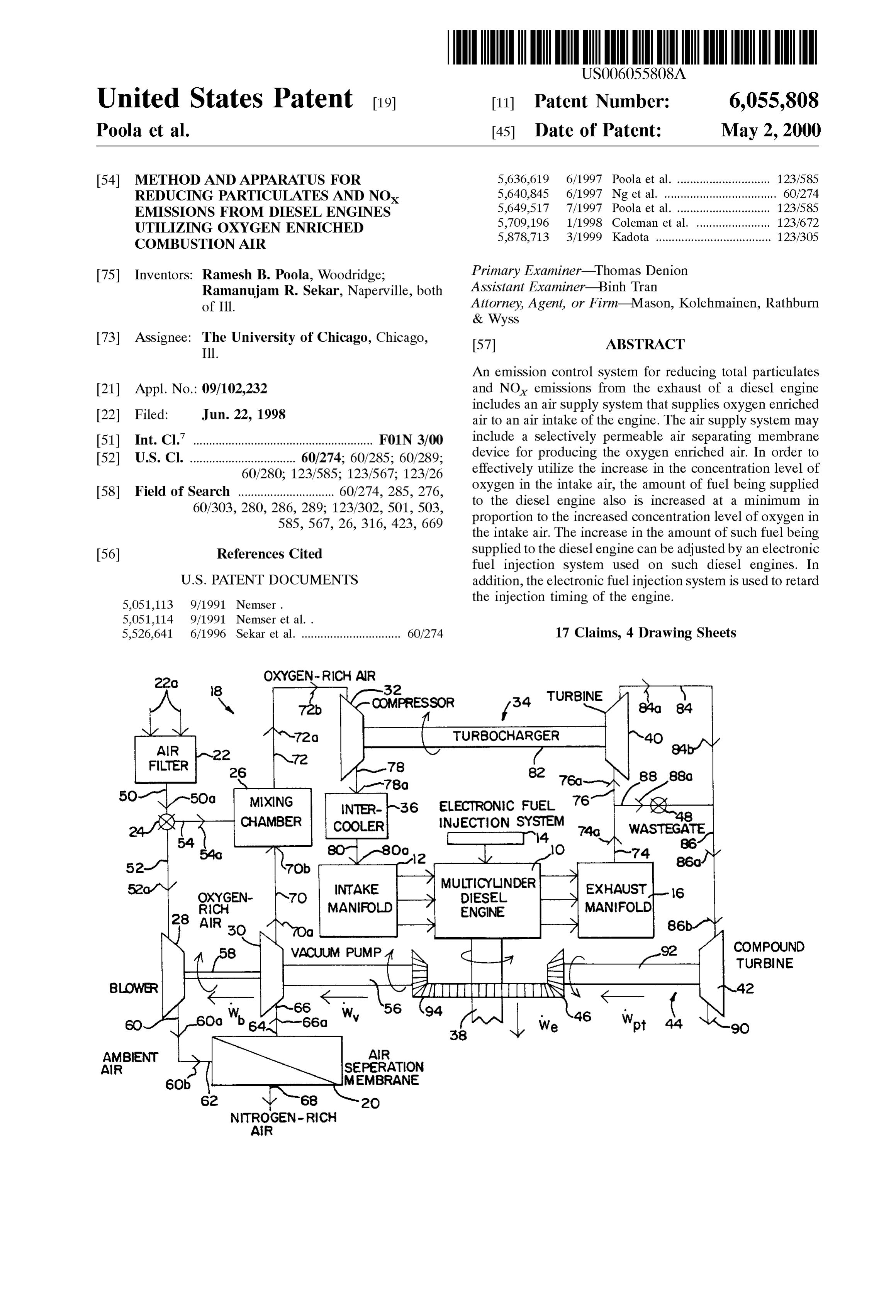
in the intake air. While Such increases in the oxygen in the supplied to the engine 10 to be combined in the engine 10 intake air and the fuel tends to reduce the amount of total with combustible fuel supplied through an electronic fuel particulates in the exhaust being emitted from the diesel injection system 14. When the intake air and the fuel are engine in part due to the increase temperature of combustion combusted in the engine 10, exhaust gases are expelled from within the engine and also tends to increase the power being an exhaust manifold 16 in the engine 10. The exhaust gases generated by the engine in part due the increase of fuel being flowing from the exhaust manifold 16 can contain a number combusted, the level of NO being emitted from the engine of different pollutants including total particulates (carbon tends to be undesirably increased. However, the level of Soot and volatile organics) and visible Smoke and oxides of NO can be controlled by having the electronic fuel injec nitrogen (NO). In order to limit the amount of these tion System retard the injection timing of the engine. By undesirable emissions that are present in the exhaust gases retarding the injection timing (i.e., delaying the time in the being emitted from the engine 10 through the exhaust engine cycle when the fuel is injected into a cylinder), the manifold 16, the engine 10 is provided with an emission length or duration of combustion is decreased resulting in control System that is generally designated by the reference less NO being formed and emitted from the engine. For numeral 18 and that embodies the present invention. example, the injection timing could be retarded between 4 15 The emission control System 18 includes an oxygen and 10 degrees of crankshaft angle. This retarding of the enrichment or air Separation membrane device 20 that engine injection timing also tends to maintain the tempera Separates nitrogen from ambient air flowing through the air ture within the cylinder at a more typical level and therefore Separation membrane device 20 Such that Oxygen enriched preSSure in the cylinder also is maintained at a typical level. air and nitrogen enriched air are produced. During the operation
In one embodiment of the present invention, the intake air flowing through of the engine 10, ambient or atmospheric air is Supplied to the intake manifold of a diesel engine at an through an air intake an air filter or air intake device 22 flows elevated pressure by means of a turbocharger driven by the bypass valve 24 to a mixing chamber 26. In order to energy obtained from the gases being exhausted from the ambient air to the air intake Supply a mixture of oxygen enriched air and exhaust manifold of the engine. In addition, a compound of the engine 10, at least a portion manifold 12 during the operation turbine can be driven by the energy obtained from the through the air filter 22 is divertedofbythetheambient 25 air flowing air intake bypass exhaust gases which are at an elevated temperature (higher valve 24 So that Such diverted air will flow to the air energy State) due to the elevated amount of oxygen in the separation membrane 20 when a blower 28 and a vacuum intake air. The energy generated by Such a turbine can be pump 30 are actuated. A portion of the nitrogen in the Supplied to the output Shaft of the diesel engine thereby at least partially offsetting any energy used to operate the ambient air diverted through the permeable membrane blower and Vacuum pump that are used in connection with device 20 due to a pressure differential established across the the permeable Separation membrane. As a result, there will membrane device 20 by the blower 28 and the vacuum pump be only possibly a small increase in the fuel consumption 30 is separated from the ambient air So that oxygen enriched air (permeate) flows through the vacuum pump 30 to the and a Small decrease in the power output of the engine due mixing chamber 26.
to the use of the permeable separation membrane. 35
The oxygen enriched air is mixed with ambient air within
BRIEF DESCRIPTION OF THE DRAWINGS the mixing chamber 26 to the extent determined by the air intake bypass valve 24 Such that oxygen enriched air is
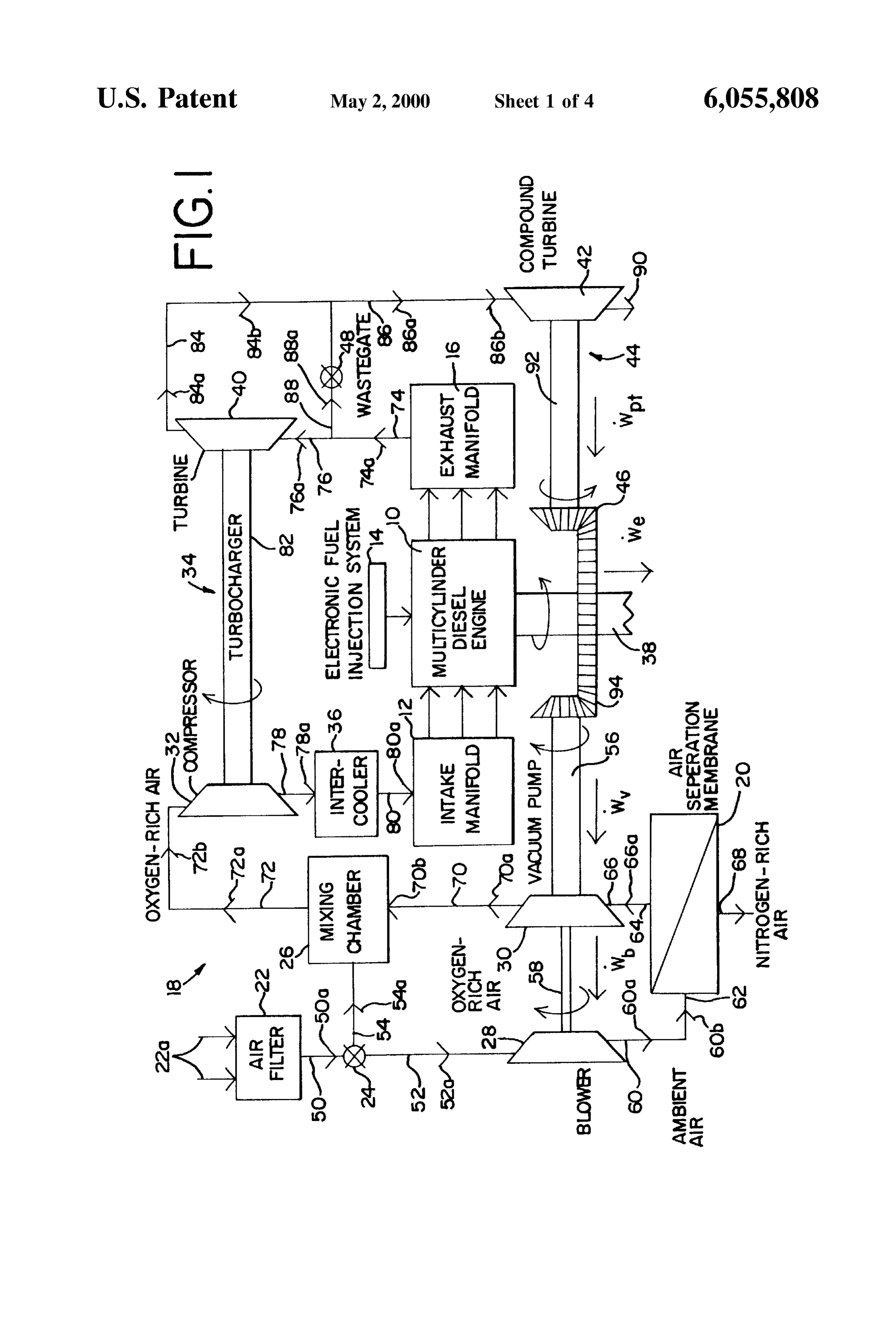
These and many other objects and advantages of the supplied to the intake manifold 12 of the engine 10 through present invention will become readily apparent from con 40 a compressor portion 32 of a turbocharger 34 and an sideration of the following detailed description of the intercooler cooler 36. While the emission control system 18 embodiment of the invention shown in the accompanying is shown in FIG. 1 as utilizing the mixing chamber 26 for drawing wherein: combining the oxygen enriched air from the membrane FIG. 1 is a diagrammatic illustration of a diesel engine device 20 and ambient air, the emission control system 18 with an emission control System which embodies the present 45 does not necessarily need to utilize Such a mixing chamber invention. 26. Instead, the oxygen enriched air generated by the mem FIG. 2 is a graph showing how the level of total particu brane device 20 and ambient air can be supplied to the intake lates in the exhaust of a typical diesel engine is affected by manifold 12 of the engine 10 in such proportions that the air adjusting the level of oxygen in the air intake of the engine, entering the engine 10 will have the correct concentration of adjusting the engine's fuel rate and adjusting the engine's 50 OXygen.
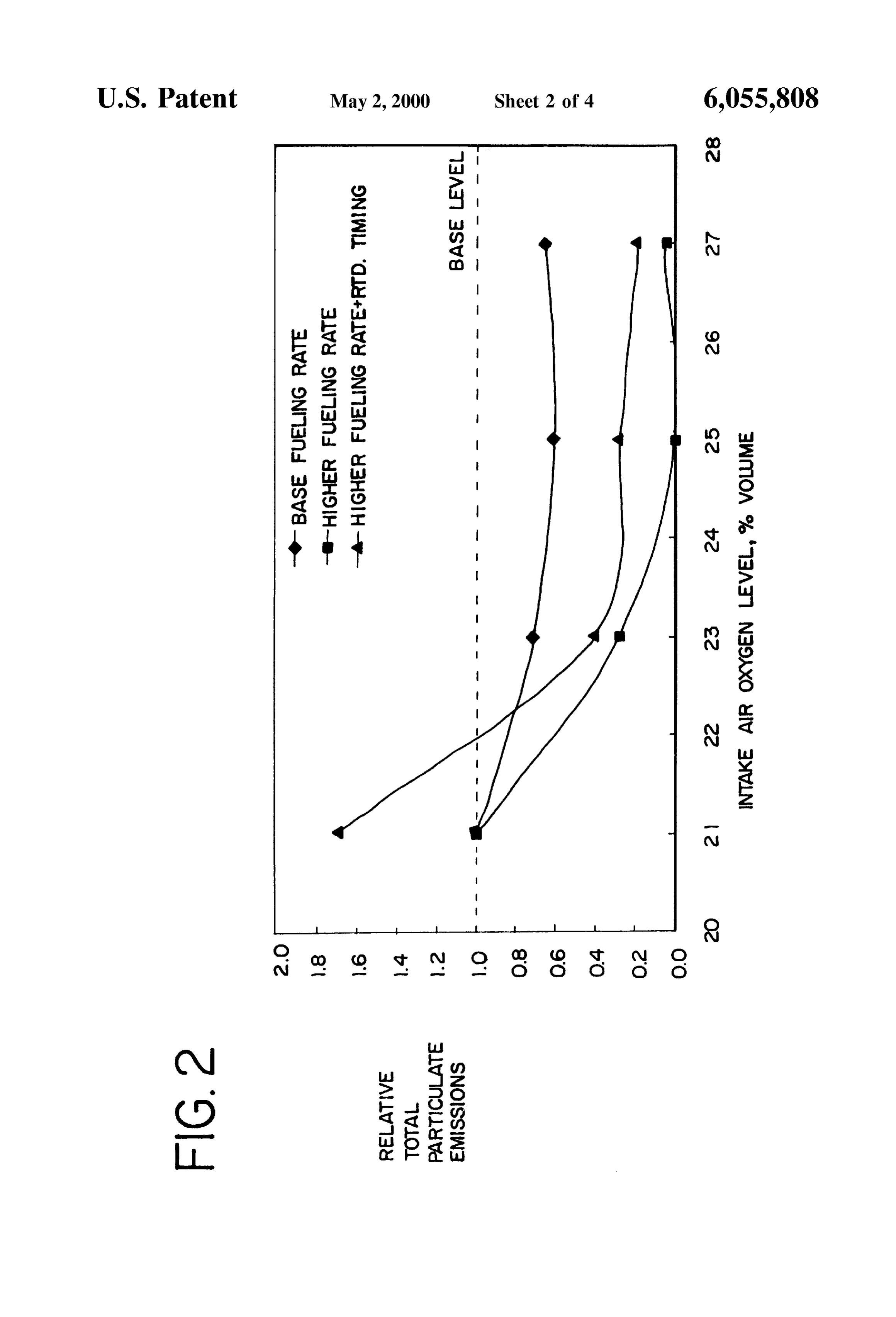
injection timing, In either case, the oxygen enriched air is mixed with fuel FIG. 3 is a graph showing how the level of NO in the Supplied through the electronic fuel injection System 14 in exhaust of a typical diesel engine is affected by adjusting the the engine 10 So as to be combusted in the cylinders of the level of oxygen in the air intake of the engine, adjusting the 55 engine 10. The timing of the combustion is controlled by the engine's fuel rate and adjusting the engine's injection tim electronic fuel injection System 14 and the combustion ing; results in the rotation of an output shaft 38 with the exhaust FIG. 4 is a graph showing how the power output from a gases manifold being expelled from the engine 10 through the exhaust 16. The exhaust gases being So expelled are at typical diesel engine is affected by adjusting the level of elevated temperatures and the energy of those exhaust gases oxygen in the air intake of the engine, adjusting the engine's 60 are used to drive a turbine portion 40 of the turbocharger 34. fuel rate and adjusting the engine's injection timing. The exhaust gases also can be used to drive a turbine portion DETAILED DESCRIPTION OF THE 42 of a compound turbine 44, the output 46 of which PREFERRED EMBODIMENT supplies energy to the output shaft 38 of the engine 10 or alternatively to the blower 28 and the vacuum pump 30. A
Referring now more specifically to FIG. 1, therein is 65 wastegate control valve 48 can be used to control the extent disclosed a diagrammatic representation of a diesel engine to which the exhaust gases flow to the turbine 40 and/or the 10 having an intake manifold 12 through which air is turbine 42.
Page 8
S 6
The oxygen level within the air being Supplied to the of the air intake bypass valve 24, at least a portion of the air intake manifold 12 of the engine 10 is at an increased flowing into the air filter 22 will flow through the air duct 52 concentration level as compared to the concentration of (as indicated by an arrow 52a), through the blower 28, oxygen in ambient air. In order to effectively utilize this through an air duct 60 (as indicated by arrows 60a and 60b) increased concentration level of oxygen in the intake air, the toward an input 62 of the membrane device 20. The ambient amount of fuel being Supplied to the diesel engine 10 also is air flowing through the ducts 52 and 60 will flow toward the increased at a minimum in proportion to the increased level input 62 of the membrane device 20 due to the differential of oxygen in the intake air. The increase in the quantity of preSSure that is established acroSS the input 62 and an outlet Such fuel being Supplied to the diesel engine 10 can be 64 of the membrane device 20 by the blower 28 and the regulated by the electronic fuel injection system 14. While Vacuum pump 30 with the pressure being higher at the input Such increases in the oxygen in the intake air and the fuel 62 as compared to the outlet 64. This differential in pressure tends to reduce the amount of total particulates in the across the membrane device 20 will result in the ambient air exhaust gases being emitted from the diesel engine 10 flowing into the input 62 and through the membrane device through the exhaust manifold 16 in part due to the increase 20 So that oxygen enriched air will permeate from the higher temperature of combustion within the engine 10 and also 15 preSSure, upstream Side of the membrane device 20 at the tends to increase the power being generated by the engine 10 input 62 to the lower preSSure, downstream Side of the in part due the increase of fuel being combusted, the level of membrane device 20 at the outlet 64 and thereby to an outlet NO in those exhaust gases tends to be undesirably duct 66 and nitrogen enriched air will likewise flow out of increased. However, the level of NO can be controlled by an outlet 68 to atmosphere. Alternatively, the differential having the electronic fuel injection System 14 retard the pressure across the input 62 and the outlet 64 of the injection timing of the engine 10. By retarding the injection membrane device 20 can be established with a compressor timing (i.e., delaying the time in the engine cycle when the that pressurizes the input 62 of the membrane device 20 fuel is injected into a cylinder), the length or duration of while the outlet 64 is maintained at atmospheric pressure. combustion is decreased resulting in leSS NO being formed The membrane device 20 is adapted to Separate oxygen and emitted from the engine 10. This retarding of the engine 25 and nitrogen present in the air being Supplied through the injection timing also tends to maintain the temperature input 62 So as to produce oxygen enriched air (permeate) at within the cylinder and therefore the cylinder pressure at the outlet 64 and nitrogen enriched air (retentate) at another relatively typical levels. It is this combination of increased outlet 68. The membrane device 20 can be of the type having concentration level of oxygen in the intake air (optimally, a Selectively permeable membrane that can Separate or 23%-25% by volume) and the increased quantity of fuel enrich gaseous mixtures. An example of Such a membrane is along with the retarding of the injection timing that results disclosed in U.S. Pat. Nos. 5,051,113 and 5,051,114, both in the decrease of both total particulates and NO in the having been issued on Sep. 24, 1991. As indicated in those exhaust gases being emitted from the exhaust manifold 16 of patents, such a membrane can be used to produce oxygen the diesel engine 10. Moreover, the power being generated enriched air by Separating oxygen and nitrogen present in by the engine 10 also is improved due to the increased 35 the air. An example of one possible configuration for Such a combustion of fuel in the engine 10. membrane device 20 is illustrated in FIGS. 6 and 7A-7C of AS previously indicated, ambient air flowing into the air U.S. Pat. No. 5,636,619 and FIGS. 3 and 3A-3C of U.S. Pat. filter 22 (as represented by arrows 22a) flows through an air No. 5,649,517, both of which patents are assigned to the duct 50 (as indicated by an arrow 50a) to the air intake assignee of the present application. Alternatively, any other bypass valve 24. The air intake bypass valve 24 controls the 40 Suitable Source of oxygen enriched air can be used in place amount of air flowing from the air filter 22 along an air duct of or in addition to the membrane device 20. 52 (as indicated by an arrow 52a) to the blower 28 and/or The particular percentage of oxygen contained within the along an air duct 54 (as indicated by an arrow 54a) to the air flowing out from the outlet 64 of the membrane device mixing chamber 26. In effect, the air intake bypass valve 24 20 and the particular percentage of nitrogen contained will determine the oxygen level in the air mixed in the 45 within the air flowing out from the outlet 68 of the mem mixing chamber 26 because it controls the amount of brane device 20 can be adjusted by providing the proper ambient air flowing to the mixing chamber 26 through the membrane device 20. In this regard, the membrane Surface duct 54 and the amount of ambient air flowing to the blower area and the preSSure differential acroSS the membrane 28 and thereby to the air separation membrane 20 which device 20 will in part determine the amount of nitrogen produces oxygen enriched air and from which the oxygen 50 Separated from the ambient air flowing into the input 62 and enriched air is Supplied through the vacuum pump 30 to the thereby the percentage of oxygen within the air flowing out mixing chamber 26. from the outlet 64. In general, the oxygen enriched air In order to provide the oxygen enriched air to the mixing flowing from the outlet 64 of a membrane device, like the chamber 26, the air intake bypass valve 24 is activated to membrane device 20, may contain from about 23% to about permit some of the ambient air from the air filter 22 to flow 55 25% oxygen concentration by Volume. along the air duct 52 as indicated by the arrow 52a. The flow Once the oxygen enriched air is produced by the mem of ambient air along the air duct 52 is caused by the actuation brane device 20, it will flow from the outlet 64 through the of the blower 28 and the vacuum pump 30 that produces a air duct 66 (as indicated by an arrow 66a), through the preSSure differential across the air Separation membrane 20. vacuum pump 30 and through an air duct 70 (as indicated by The blower 28 and the vacuum pump 30 can be mechani 60 arrows 70a and 70b) to the mixing chamber 26. The level of cally driven as diagrammatically shown in FIG. 1 from oxygen in the oxygen enriched air being Supplied from the energy supplied from the rotating shaft 38 of the engine 10 mixing chamber 26 via an air duct 72 (as indicated by arrows or the compound turbine 44 through turbine shafts 56 and 58 72a and 72b) to the compressor 32 is in part dependent on respectively. Alternatively, the blower 28 and the vacuum the concentration of oxygen in the oxygen enriched air pump 30 can be driven by electric motors powered by the 65 flowing from the outlet 64 of the air separation membrane 20 electrical system of the engine 10. With the blower 28 and and in part dependent on the amount of ambient air that is the vacuum pump 30 So actuated and depending on the State Supplied directly to the mixing chamber 26 through the air
Page 9
intake bypass valve 24 and the air duct 54 and through that Such NO in those exhaust gases can be reduced by retarding valve 24 to the air separation membrane 20. As previously the injection timing of the engine 10 in addition to increasing indicated, the mixing chamber 26 is not necessarily required the concentration level of oxygen in the intake air and because both oxygen enriched air and ambient air can be increasing the fuel quantity being Supplied to the engine 10. supplied to the intake manifold 12 of the engine 10 resulting The injection timing can be controlled by the electronic fuel in the proper concentration of oxygen enriched air being injection System 14. The retarding of the injection timing Supplied to the engine 10. No matter how the oxygen effectively delays the time when fuel is injected in a cylinder enriched air is Supplied to the engine 10, typically for of the engine 10. This delay lessens the combustion time and engines 10 of the type with which the emission control thereby decreases the amount of oxides of nitrogen that is System 18 is used the oxygen concentration by Volume in the formed during combustion. While the extent to which the oxygen enriched air being Supplied to the engine 10 will be injection timing is decreased depends on the concentration increased to 23% to 25% by volume (this is compared to the levels of oxygen in the intake air and the characteristics of concentration of oxygen in ambient air which is approxi the engine 10, a retarding of injection timing in the range of mately 21% by volume). 4 to 10 degrees of crank angle would tend to be Sufficient to The oxygen enriched air flowing in the air duct 72 is 15 aid in diminishing the amount of NO present in the exhaust compressed (i.e., elevated in pressure) by the compressor gases being emitted from the exhaust manifold 16 of the portion 32 of the turbocharger 34. The turbine portion 40 of engine 10.
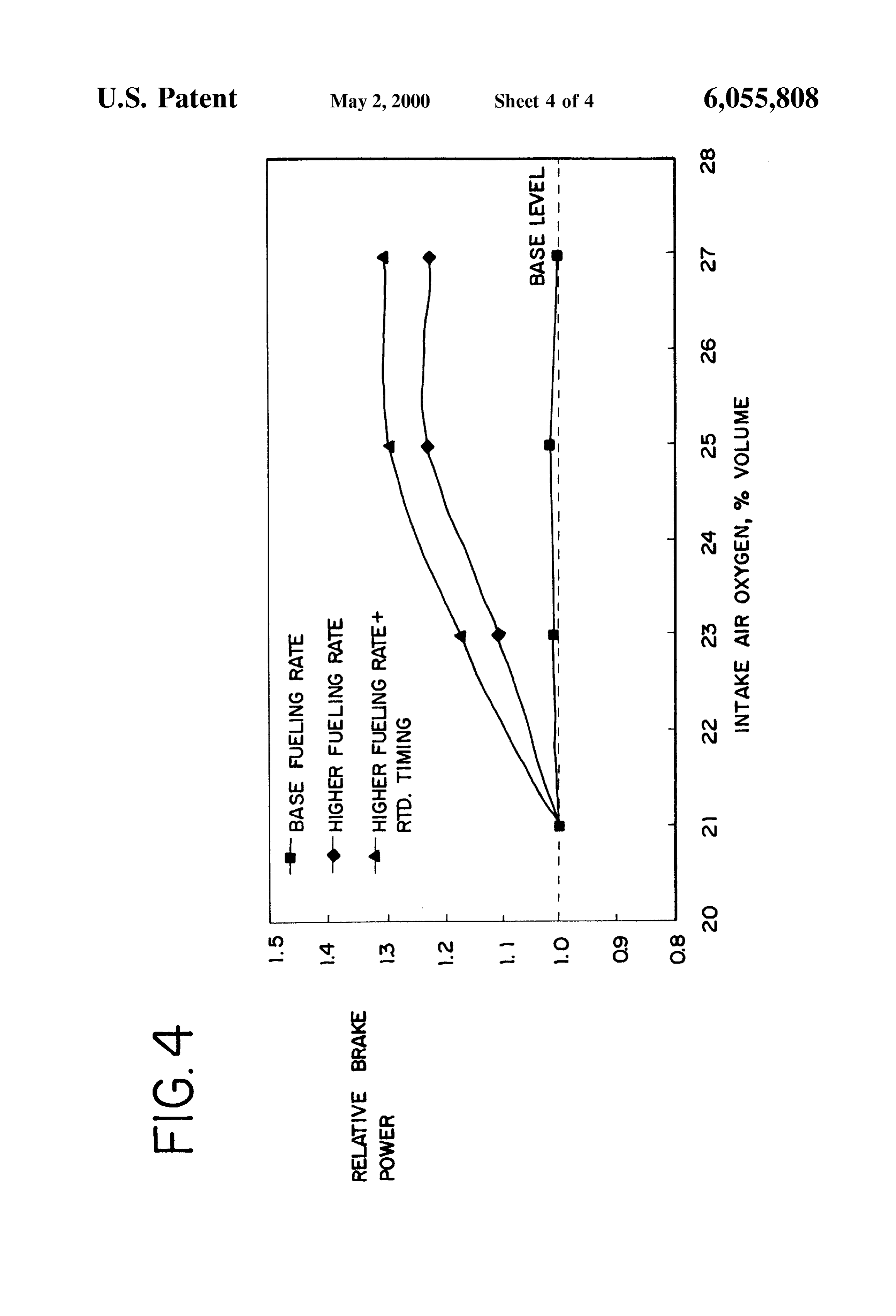
the turbocharger 34 is driven by the energy from the exhaust In this regard, the graphs of FIGS. 2, 3 and 4 demonstrate gases being emitted from the exhaust manifold 16 through how the increase in oxygen concentration in the intake air, an air duct 74 (as indicated by an arrow 74a) and an air duct the increase in fuel quantity and the retarding of injection 76 (as indicated by an arrow 76a). The energy from such timing can reduce both the total particulates and NO exhaust gases that are at elevated temperatures is used to Simultaneously within the exhaust gases being emitted from drive the turbine portion 40 of the turbocharger 34 such that the exhaust manifold 16 of the engine 10 and also increase a shaft 82 is rotated thereby driving the compressor portion the power being generated by the engine 10. These graphs 32. The compressor portion 32 compresses the intake air 25 are based on information from a typical two cylinder flowing through the air duct 72 such that the intake air research (large bore, medium speed, two-stroke) diesel flowing out from the compressor portion 32 through an air engine running at a full load.
duct 78 (as indicated by an arrow 78a) to the inter-cooler 36 Referring first to FIG. 2, that graph compares the amount is at an appropriate elevated pressure when it flows out from of total particulates (shown on a relative Scale or a normal the inter-cooler 36 via an air duct 80 (as indicated by an ized index above or below a base or index level) that is arrow 80a) and supplied to the intake manifold 12. The present in the exhaust gases of a diesel engine depending on inter-cooler 36 is designed to act as a heat eXchanger to cool the concentration level of oxygen (shown as a percentage of the intake air flowing into the intake manifold 12. By Volume of the intake air) when a typical amount of fuel (base cooling the intake air, NO formed in the engine 10 tends to fueling rate) is Supplied to the engine (diamond shaped be decreased. 35 points), when an increased amount of fuel (higher fueling
In view of the fact that the intake air has a higher rate) isboth Supplied to the engine (Square shaped points) and concentration of oxygen than ambient air, the amount of fuel when an increased amount of fuel is Supplied and the being Supplied to the engine 10 by the fuel injection System injection timing is retarded (in the case of this graph, the injection timing was retarded approximately 7 degrees of 14 also should be increased. This increase in fuel quantity 40 crank Shaft angle)(triangular shaped points). AS can be can be at a minimum proportional to the increase in the oxygen content of the intake air. For example, the fuel discerned from the graph of FIG. 2, the amount of total quantity can be increased by the ratio of the increase of the particulates decrease in all cases when the concentration weight of oxygen in the intake air over the weight of oxygen level of oxygen in the intake air is increased above the in ambient air divided by the weight of oxygen in ambient 45 concentration level of oxygen in ambient air. The graph of FIG. 3 Similarly compares what is happening air. If the quantity (weight) of fuel being Supplied to the engine 10 when ambient air is used is “F1, the weight of with respect to oxides of nitrogen (NO) (shown on a oxygen in ambient air is "AA’ and the weight of oxygen in relative Scale or normalized indeX above or below a base or the intake air is “AO”, then the quantity (weight) “F2” of the index level) in the exhaust gases of a diesel engine depend fuel that should be supplied to the engine 10 by the fuel 50 ing on the concentration level of oxygen (shown as a injection System 14 when oxygen enriched air is used could percentage of Volume of the intake air) when a typical be determined by the following formula: amount of fuel (base fueling rate) is Supplied to the engine (Square shaped points), when an increased amount of fuel (higher fueling rate) is Supplied to the engine (diamond shaped points) and when both an increased amount of fuel
While increasing the concentration level of oxygen in the 55 is Supplied and the injection timing is retarded (in the case intake air being Supplied to the engine 10 through the intake of this graph, the injection timing was retarded approxi manifold 12 with a commensurate increase in the fuel being mately 7 degrees of crank shaft angle)(triangular shaped Supplied to the engine 10 through the fuel injection System points). AS can be discerned from this graph, the amount of 14 tends to diminish the amount of total particulates in the NO in the exhaust gases tends to increase in all cases when exhaust gases flowing from the exhaust manifold 16 of the 60 the concentration level of oxygen in the intake air is engine 10 and also tends to increase the power being increased. On the other hand, the graph of FIG. 3 does generated by the engine 10 in part due the increase of fuel indicate that the amount of NO in Such exhaust gases are being combusted, the NO in Such exhaust gases tend to be maintained at an acceptable level below a base level even at an undesirable elevated amount. This is due in part to the when the oxygen level in the intake air is increased to around fact that the increase temperatures of combustion within the 65 23% of the volume of the intake air, the base fuel rate is cylinders of the engine 10 tend to form more oxides of increased and the injection timing of the engine is retarded. nitrogen in those exhaust gases. However, the amount of At that same level of oxygen concentration, the graph of
Page 10
FIG. 2 shows that the total particulates in the exhaust gases temperatures tend to be higher than normal due to the are at a relatively low level, well below a base or acceptable increase of oxygen in the intake air) So that energy can be level, when the oxygen concentration of the intake air is at imparted to the turbine portion 40 of the turbocharger 34 that same approximate 23% by volume, the base fuel rate is from this exhaust gas. The exhaust gases flow out from the increased and the injection timing of the engine is retarded. turbine portion 40 through an air duct 84 (as indicated by Accordingly, the graphs of FIGS. 2 and 3 confirm that the arrows 84a and 84b) and through another air duct 86 (as levels of both total particulates and NO in the exhaust gases indicated by arrows 86a and 86b) to the turbine portion 42 of a diesel engine can be reduced to acceptable levels when of the compound turbine 44. The amount of and the tem the oxygen concentration of the intake air is increased perature of the exhaust gases flowing to the compound modestly above the concentration of oxygen in ambient air turbine 44 can be controlled to Some extent by the wastegate (for example, increased to approximately 23% oxygen by control valve 48. When that wastegate control valve 48 is Volume), the amount of fuel being Supplied to the engine is opened to at least Some extent, a portion of the exhaust gases increased (for example, proportional to the increase in the flowing in the air duct 74 directly from the exhaust manifold amount of oxygen in the intake air) and the injection timing 16 will be diverted along an air duct 88 (as indicated by an of the engine is retarded (for example, retarded by 7 degrees 15 arrow 88a) and then to the air duct 86 so that the diverted crank Shaft angle). exhaust gases will flow as indicated by the arrows 86a and The graph of FIG. 4 compares what is happening with 86b along the air duct 86 to the turbine portion 42 of the respect to the brake power being generated by a typical compound turbine 44.
diesel engine (shown on a relative Scale or normalized index The energy contained in the exhaust gases being expelled above or below a base or index level) depending on the from the exhaust manifold 16, particularly in view of the concentration level of oxygen (shown as a percentage of elevated temperatures of those gases caused by the increased Volume of the intake air) when a typical amount of fuel (base levels of oxygen in the intake air of the engine 10, can be fueling rate) is Supplied to the engine (Square shaped points), used in driving the turbine 42 of the compound turbine 44. when an increased amount of fuel (higher fueling rate) is In this regard, the exhaust gases flow through the turbine Supplied to the engine (diamond shaped points) and when 25 portion 42 and then is exhausted to atmosphere as indicated both an increased amount of fuel is Supplied and the injec by an arrow 90. While the disclosed embodiment of the tion timing is retarded (in the case of this graph, the injection emission control system 18 shown in FIG. 1 indicates that a timing was retarded approximately 7 degrees of crank shaft compound turbine 44 can be used to add to the energy of the angle)(triangular shaped points). AS can be discerned from crankshaft 38, other devices can be used Such as a positive this graph, the power output from the engine tends to Screw expander, turbochargers, and other bottoming cycles increase as the amount of fuel being combusted within the that can convert the energy in the exhaust gases into engine increases. In the case where the Oxygen level in the mechanical energy. The amount of energy generated by the intake air is increased to around 23%-25% of the Volume of compound turbine 44 is partly dependent on the amount of the intake air, the base fuel rate is increased and the injection the exhaust gases that are Supplied directly from the exhaust timing of the engine is retarded, the output power is 35 manifold 16 under the control of the wastegate control valve increased above the base level or the level of output power 48 as opposed to the exhaust gases that first flow through the of a normally running engine. Consequently, the graphs of turbine 40.
FIGS. 2, 3 and 4 indicate that the output of the engine can In the case of the compound turbine 44, the amount of be increased while the total particulates and the NO in the energy produced by the turbine 42 and imparted to a shaft 92 exhaust gases are maintained at a relatively low level, well 40 and thereby through the output 46 to the crankshaft 38 is below a base or acceptable level, when the oxygen concen represented in FIG. 1 as W. The amount of energy being tration of the intake air is increased modestly above the imparted to the crankshaft by both the engine and the concentration of oxygen in ambient air (for example, compound turbine 44 is represented in FIG. 1 as W. On the increased to approximately 23% oxygen by volume), the other hand, the amount of energy being taken from the amount of fuel being Supplied to the engine is increased (for 45 crankshaft 38 at an output 94 to drive the vacuum pump 30 example, proportional to the increase in the amount of through the shaft 56 is represented in FIG. 1 as W. and to oxygen in the intake air) and the injection timing of the drive the blower 28 through the shaft 58 as W. Ideally, W., engine is retarded (for example, retarded by 7 degrees crank should be equal to or greater than the sum of W. and W. So shaft angle). that the total amount of energy W. will not be decreased due While the use of the emission control system 18 aids in 50 to the emission control system 18. Even if the amount of reducing both the total particulates and the NO present in energy W. imparted to the crankshaft 38 is decreased the exhaust gases being expelled from the exhaust manifold Slightly, that decrease in energy is offset by the advantage of 16 of the engine 10, a certain amount of additional energy decreasing the amount of total particulates and NO in the over the energy normally needed to operate the engine 10 is exhaust gases being expelled to the atmosphere from the needed in order for the oxygen to be produced by the 55 engine 10.
membrane device 20. As previously discussed, the blower Obviously, many modifications and variations of the 28 and the vacuum pump 30 create a sufficient differential present invention are possible in light of the above teach preSSure acroSS the Separation membrane device 20 So that ings. Thus, it is to be understood that, within the Scope of the the resulting oxygen enriched air can be Supplied to the appended claims, the invention may be practiced otherwise mixing chamber 26 and then to the intake manifold 12 of the 60 than as Specifically described above. engine 10. At least Some of this additional energy can be What is claimed and desired to be secured by Letters provided by the compound turbine 44. As also previously Patent of the United States is:
discussed, the exhaust gases being expelled from the exhaust 1. An emission control System for a combustion engine to manifold 16 flow along the air duct 74 (as indicated by the limit pollutants in exhaust gases emitted from an exhaust of arrow 74a) and the air duct 76 (as indicated by the arrow 65 Said engine, Said emission control System comprising: 76a) through the turbine portion 40 of the turbocharger 34. a Source of oxygen enriched air in fluid communication These exhaust gases are at elevated temperatures (in fact, the with an air intake of Said engine, Said oxygen enriched
Page 11
air being Supplied to Said air intake contains approxi 11. A method of reducing the amount of oxides of nitrogen mately 23%-25% oxygen concentration by volume; and particulates in gases being emitted from an exhaust of an and internal combustion engine, Said method comprising: a fuel and timing control System, Said fuel and timing Supplying oxygen enriched air contains approximately control System controlling the amount of fuel being 23%-25% oxygen concentration by volume to an air Supplied to Said engine Such that the amount of fuel is intake of Said engine;
increased at a minimum in proportion to the amount of Supplying an increased amount of fuel to Said engine in oxygen in Said oxygen enriched air and the injection proportion to the amount of oxygen in Said oxygen timing of Said engine is retarded approximately 4-10 degrees of crank Shaft angle. enriched air; and 2. An emission control System as Set forth in claim 1 retarding the injection timing of Said engine approxi wherein Said Source of oxygen enriched air is a Selectively mately 4-10 degrees of crank Shaft angle. permeable membrane for producing oxygen enriched air that 12. A method as Set forth in claim 11 wherein Said oxygen is Supplied to Said air intake. enriched air is Supplied by a Selectively permeable mem 3. An emission control System as Set forth in claim 2 15 brane.
wherein Said membrane produces oxygen enriched air con 13. A method as set forth in claim 12 wherein a blower taining about 23%-25% oxygen concentration by volume. and a vacuum pump maintain a differential pressure acroSS 4. An emission control System as Set forth in claim 2 Said permeable membrane.
including an exhaust driven device for Supplying energy 14. A method as set forth in claim 11 wherein said fuel from Said exhaust gases So as to enable Said membrane to being Supplied to Said engine is at a minimum in proportion produce Said oxygen enriched air. to the weight of oxygen in Said oxygen enriched air as 5. An emission control System as Set forth in claim 2 compared to the weight of oxygen in ambient air. including a pressure differential means associated with Said 15. A method of reducing the amount of oxides of membrane to establish a differential pressure acroSS Said nitrogen membrane So that ambient air flows through Said membrane exhaust ofanda particulates 25 in gases being emitted from an and one of the products of Said membrane is oxygen output power diesel engine and increasing the amount of from Said engine, Said method comprising:
enriched air.
6. An emission control system as set forth in claim 5 producing oxygen enriched air by processing ambient air wherein Said pressure differential means includes a blower through a Selectively permeable membrane, for producing an elevated pressure at an input of Said mixing Said oxygen enriched air from Said membrane membrane and a vacuum pump associated with an output of with ambient air So as to have a resulting oxygen Said membrane from which Said oxygen enriched air flows. enriched air with approximately 23%-25% oxygen 7. An emission control system as set forth in claim 6 concentration by Volume;
wherein Said blower and Said vacuum pump are mechani Supplying Said resulting oxygen enriched air into an air cally driven at least in part by a driving means driven by 35 energy from Said exhaust gases being emitted from Said intake of Said engine;
exhaust of Said engine. Supplying an increased amount of fuel to Said engine at a 8. An emission control System as Set forth in claim 1 minimum in proportion to the amount of oxygen in Said including a mixing chamber in fluid communication with Oxygen enriched air, and
Said air intake, Said mixing chamber receiving ambient air 40 retarding the injection timing of Said engine approxi and Said oxygen enriched air from Said Source of oxygen mately 4-10 degrees of crank Shaft angle. enriched air and Supplying a mixture thereof to Said air 16. A method as set forth in claim 15 wherein said fuel intake. being Supplied to Said engine is at a minimum in proportion 9. An emission control system as set forth in claim 8 to the weight of oxygen in Said resulting oxygen enriched air wherein Said mixture of oxygen enriched air and ambient air 45 as compared to the weight of oxygen in ambient air. contains about 23%-25% oxygen concentration by volume. 17. A method as set forth in claim 15 wherein a differential 10. An emission control system as set forth in claim 1 preSSure is maintained acroSS Said permeable membrane So wherein Said fuel and timing control System retards Said that Said oxygen enriched air will be produced. injection timing of Said engine approximately 7 degrees of crank shaft angle. k k k k k
Provenance
- Collection
- Cited prior art
- Original PDF
- patentimages.storage.googleapis.com →
- Filed
- 1998-06-22
- Pages
- 11
- Method
- pdftotext (the PDF's own text layer) + pdftoppm 300dpi page scans
- Source
- Google Patents bibliographic record
- Granted
- 2000-05-02
- Inventors
- Ramesh B. Poola; Ramanujam R. Sekar; University of Chicago
- Transcribed from
- patentimages.storage.googleapis.com →