patent · US4219394
Membrane assembly for electrolytic cells
26 August 1980
Page 1 — bibliographic record
United States Patent (19) (11) 4,219,394 Babinsky et al. (45) Aug. 26, 1980 (54) MEMBRANE ASSEMBLY FOR 3,634,213 1/1972 Coates .................................. 204/252 ELECTROLYTIC CELLS 4,025,405 5/1977 Dotson et al. ......................... 204/98 75) Inventors: Andrew D. Babinsky, Chagrin Falls; OTHER PUBLICATIONS Charles J. Hora, Painesville; Edward "Electroforming' by Spiro, 2nd Ed., 1971, p. 23. J. Peters, Chardon; Wayne P. Zeman,
Richmond Heights, all of Ohio Primary Examiner-R. L. Andrews
Attorney, Agent, or Firm-John P. Hazzard (73) Assignee: Diamond Shamrock Corporation, (57) ABSTRACT Dallas, Tex.
In an electrolytic cell of the membrane type wherein the anolyte and catholyte are separated by a hydraulically 22) Filed: Mar. 22, 1978 impermeable membrane, the improvement comprising limiting the hydraulically impermeable membrane por
Related U.S. Application Data tion of the divider between anolyte and catholyte cham bers to that area which is between the active areas of the (63) Continuation-in-part of Ser. No. 774,800, Mar. 7, 1977, anode and cathode while all other areas between catho abandoned.
lyte and anolyte chambers are nonpermeable so as to 51) Int. Cl’.......................... C25B 1/16; C25B 1/26; minimize back-migration of undesirable ions which C25B 9/00; C25B 13/02 decrease overall current efficiency. Specifically, in a 52) U.S. C. ...................................... 204/98; 204/128; chlor-alkali cell an electrode would be enclosed in a 204/258; 204/296 fluorinated ethylene propylene enclosure having win 58) Field of Search ........... 204/98, 128, 296, 252-266 dow-like openings therein made from Nafion type hy References Cited draulically impermeable cation exchange membrane, 56) said window-like openings exposing only active elec
3,072,545 1/1963 Juda et al. ............................ 204/257 3,287,250 li/1966 Brown et al. ........................ 204/263 10 Claims, 5 Drawing Figures
Page 2
Drawing sheet — no readable text.
Page 3
Drawing sheet — no readable text.
Page 4
Drawing sheet — no readable text.
Page 5
wherever the membrane was joined to itself and espe
MEMBERANE ASSEMBLY FOR ELECTROLYTEC cially in areas of stress such as along edges when the CELLS membrane is shaped at great angles to closely fit the
RELATED APPLICATIONS
cathode shape,
The advantages of the instant invention are further
This application is a continuation-in-part of U.S. ap magnified when it is considered that most commercial plication Ser. No. 774,800, filed Mar. 7, 1977, now aban electrolytic operations consist of a large plurality of doned. individual electrolytic cells wherein the use of imper
BACKGROUND OF THE INVENTION
meable envelopes having hydraulically permeable 10 membrane windows therein between active areas of the
In commercial practice, as for example in the chlor electrodes are used. Such envelopes can be intercon alkali industry, diaphragm type electrolytic cells have nected and preferably are as for example, when a multi been most common until recent years. In these dia cell diaphragm type operation is converted to a mem phragm type cells the diaphragms separated the anolyte brane type unit.
and catholyte chambers. Normally, these diaphragms 15 were simply an asbestos mat or the like and in any case BRIEF DESCRIPTION OF THE INVENTION were hydraulically permeable. Normal practice was to In its broadest sense, the instant invention comprises build such an asbestos diaphragm between opposed limiting the hydraulically impermeable membrane di anodes and cathodes so that the diaphragm extended 20 viding the anolyte and catholyte chamber in an electro therebetween to the walls of the cell or to clamping lytic cell to that area between the electrodes which is means at the wall surfaces. Another arrangement com more active electrolytically while separating the ano mon in the prior art was to have the diaphragm material lyte to entirely surround the cathode and in fact be depos withand catholyte chamber in inactive electrode areas a nonpermeable material which is sealed to or ited on the cathode so as to cover all surfaces thereof. In all cases however, the anolyte, due to the hydraulic 25 coated on the membrane separator, permeability of the diaphragm would be essentially in In membrane type chlor-alkali cells a hydraulically impermeable membrane made of such materials as Na contact with all surfaces of the cathode whether they be fion active or inactive. completely separate the anolyte and catholyte This same practice has been carried over into electro chambers. In the simplest case where there is a single lytic cells employing hydraulically impermeable mem 30 anode and a single cathode, the membrane of the instant branes between anolyte and catholyte chambers. Stan invention would consist of a flat Nafion sheet conform dard practice has been to place a membrane wall be ing to the shape and size of the active portion of the tween anode and cathode to eliminate hydraulic com electrodes. This sheet of Nafion would be fixedly at munication between each chamber. Of necessity, such tached to a frame of impermeable material which would use of a sheet membrane covered both active and inac 35 extend to the sides and bottom of the cell so as to com tive areas between the electrodes. pletely separate the anolyte and catholyte chambers. Furthermore, in membrane cells wherein a single The nonpermeable framing material would preferably cathode forms a cell with two anodes the practice has be a material such as fluorinated ethylene propylene been to enclose the cathode in a hydraulically imperme sheet which would eliminate back migration of hy able membrane envelope wherein the membrane pre 40 droxyl ions from the catholyte chamber in the inactive vented liquid communication with the cathode in the areas between the anolyte and catholyte chambers, thus electrolytic cell. Such an envelope was open only at the increasing cell current efficiency accordingly while top above the liquid level to allow the escape of gases formed during electrolysis. Here again, all areas of the inminimizing a given membrane costs due to lesser use of Nafion cell.
cathode were covered without discrimination between 45 In more complex arrangements such as where a single active and inactive surfaces. Such complete enclosure cathode of the cathode with a hydraulically impermeable mem inventioninteracts would with a plurality of anodes, the present envisage an impermeable envelope brane is detrimental for a number of reasons. For exam surrounding the cathode with hydraulically imperme ple, consider such a membrane completely enclosing able membrane windows therein conforming to the size the cathode in a chlor-alkali cell. Between the inactive 50 regions of the cathode and membrane there will be and shape of the electrodes and positioned between the caustic. However, since there will be little electrolysis active areas of the interacting cathode and anodes. Nor occurring in these areas, a significant amount of back mally, in actual practice a plurality of such envelopes migration of hydroxyl ion would occur which would would be interconnected and would be open at the top result in a serious loss in cell current efficiency. 55 to allow chlorine gas to escape from the anolyte portion Also, the membrane material is more expensive com of the cell for collection, while the envelopes would pared to a nonpermeable material such as used in the form a closed chamber over the cathodes so as to keep instant invention to separate the anolyte and catholyte the hydrogen generated at the cathodes separated from chamber in inactive electrode areas. the chlorine and have such hydrogen withdrawn from Another advantage of the instant invention over the 60 the side of the commercial cell.
prior are practices is that fabrication of a membrane In addition, such a plurality of envelopes may be envelope is extremely difficult and in any event more shaped so as to interact with the sidewalls and/or bot difficult than fabricating an envelope of nonpermeable tom of the cell to effect proper alignment. For example, material with membrane windows. Due to its relatively the envelopes could contain protrusions which fit into delicate nature, membranes are more difficult to fabri 65 apertures on the cell bottom or cell walls or in fact holes cate especially in cases where you are attempting to could extend through the bottom of the envelopes and form an envelope which would completely surround an the anodes could protrude there through into positions electrode. The potential leakage problems would exist ing slots in the cell bottom while at the same time seal
Page 6
ing the membrane around the hole in the lower end of to essentially that area between interacting electrodes the envelopes. intersected by said imaginary unobstructed straight BRIEF DESCRIPTION OF THE DRAWINGS lines between interacting electrodes in the plane in which the membrane is placed, said area being referred
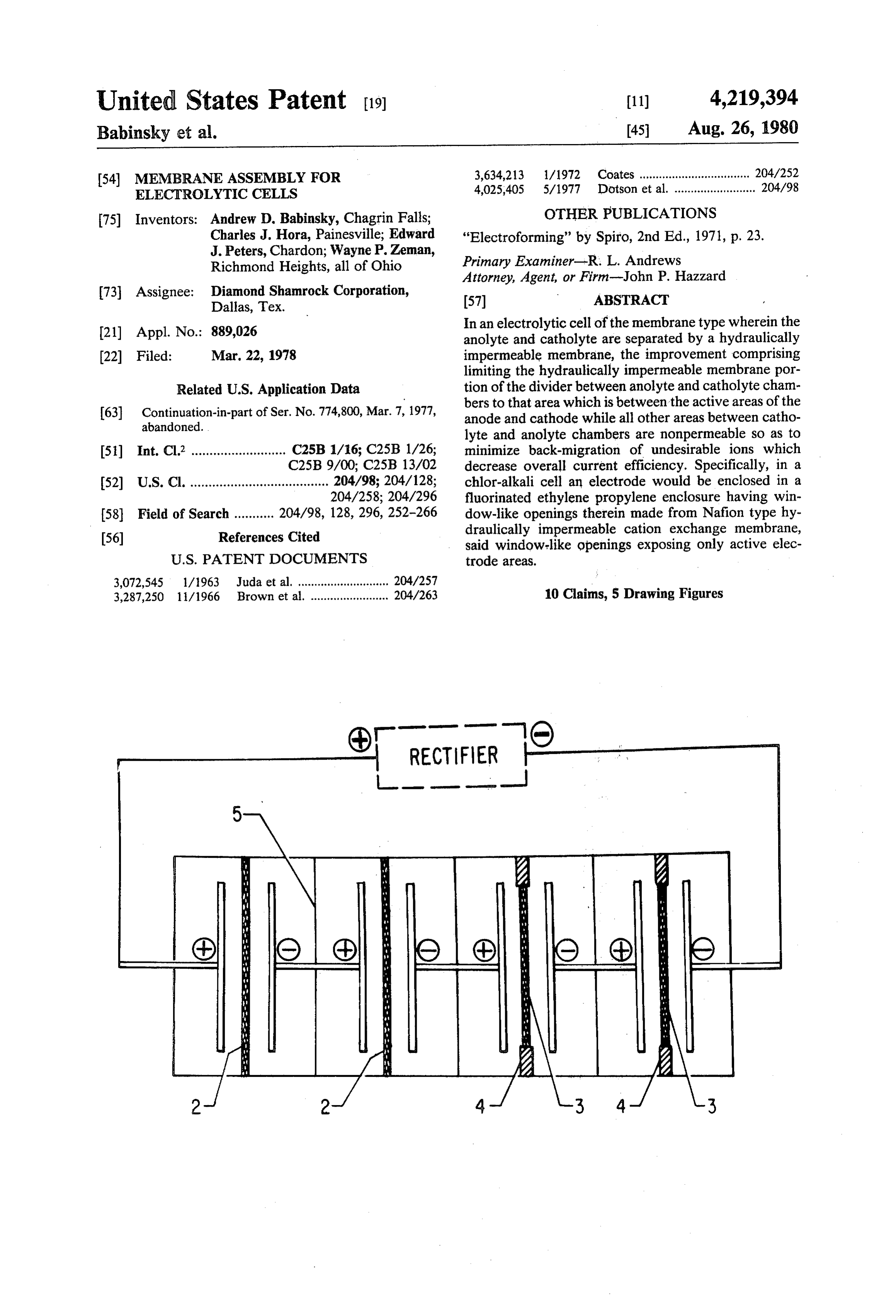
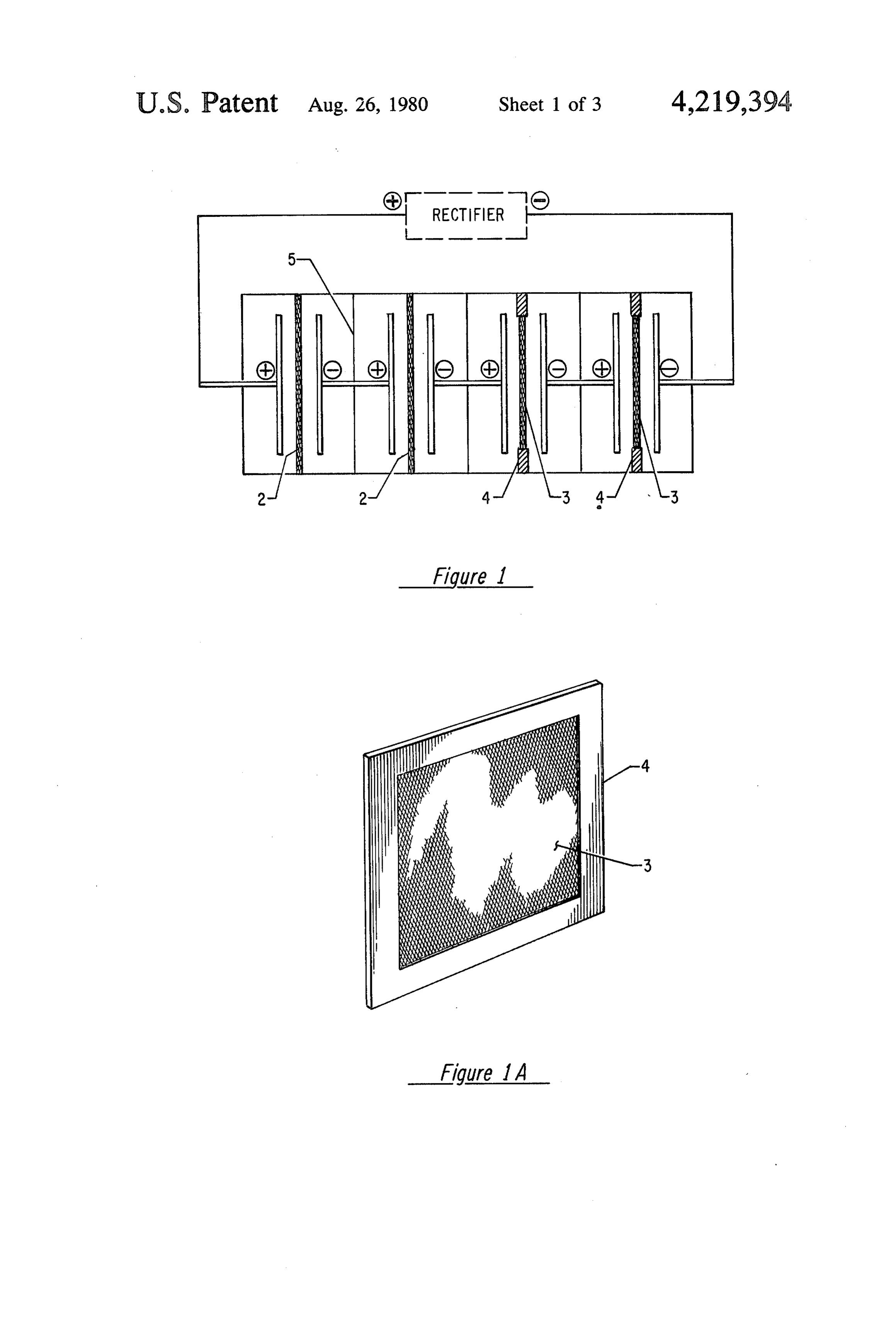
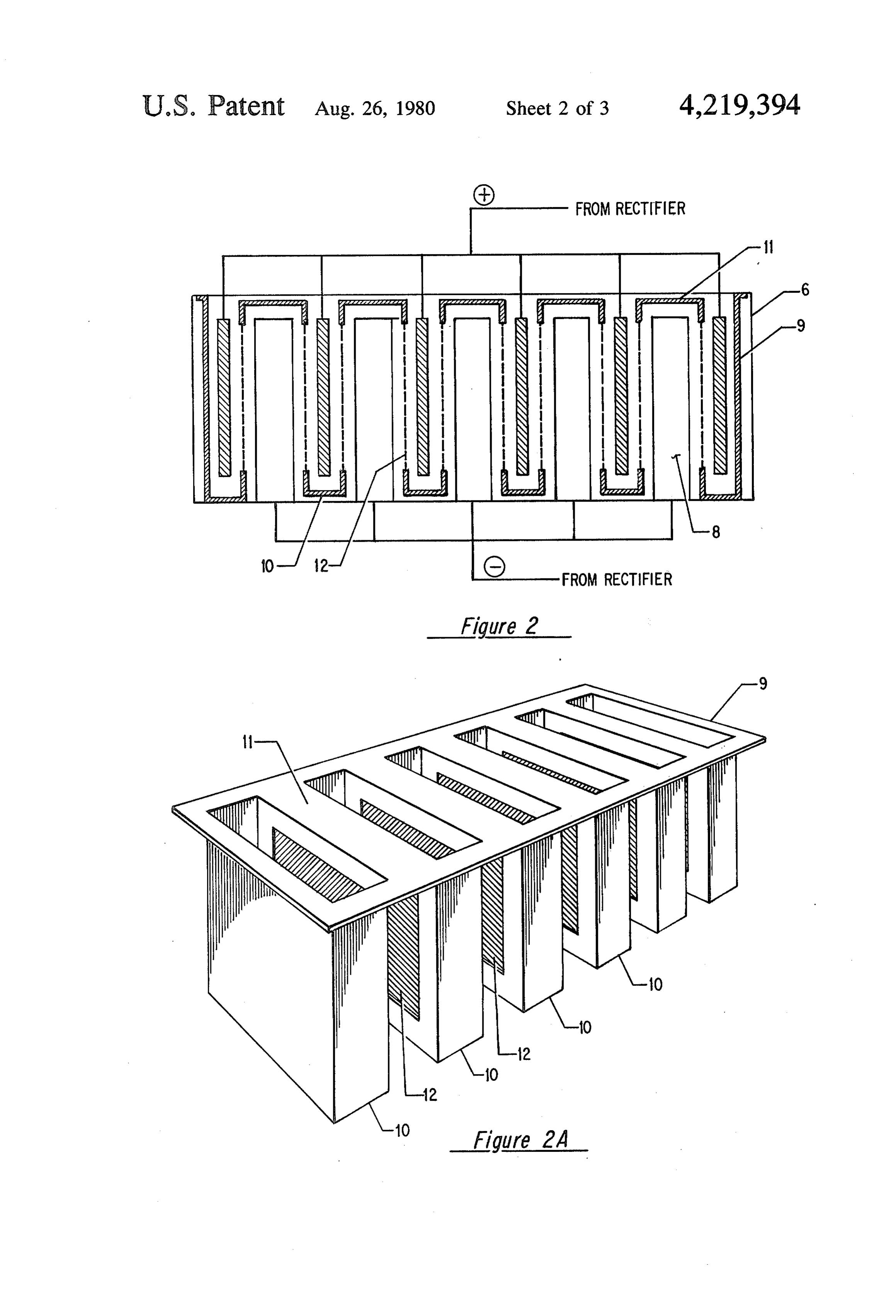
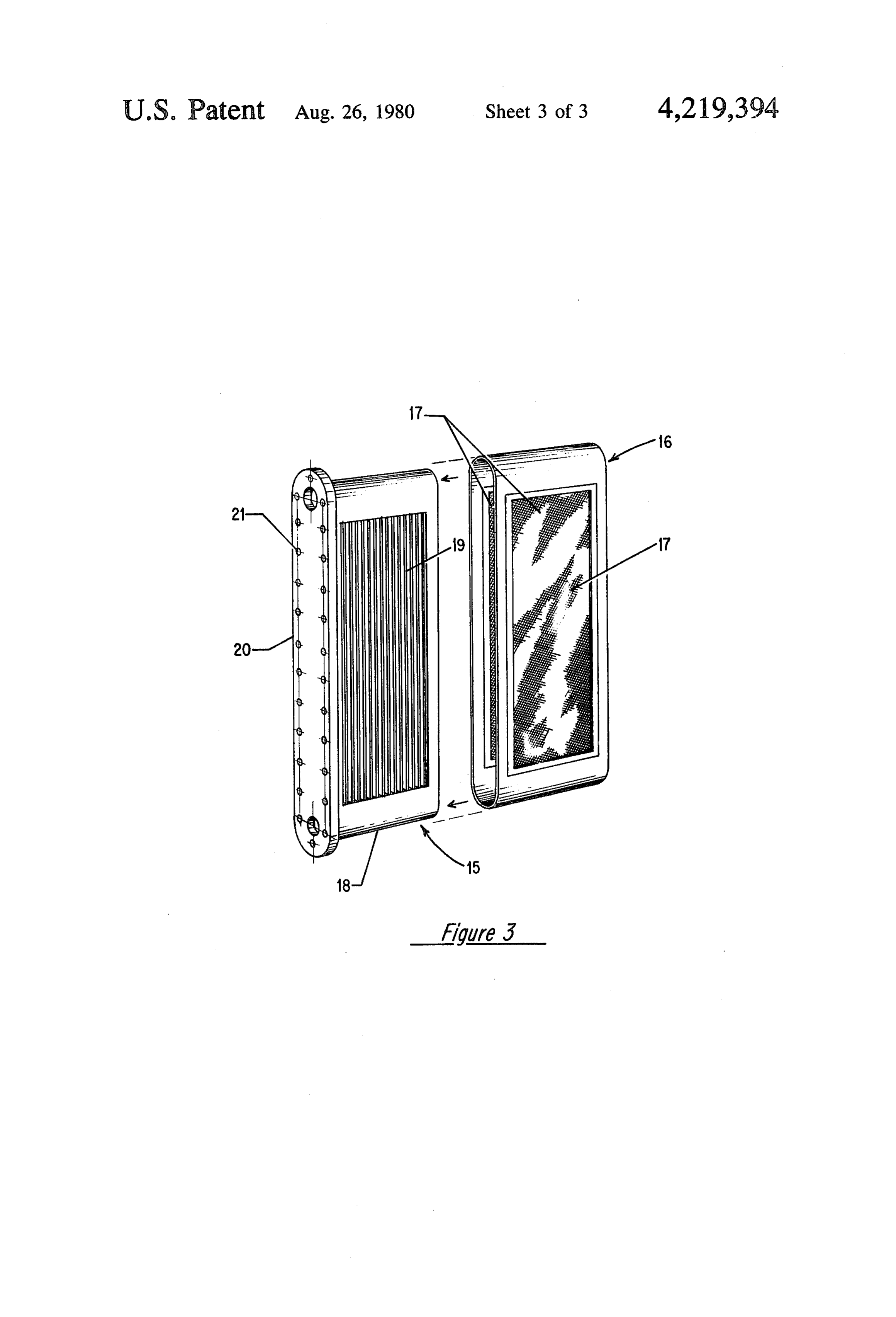
FIG. 1 of the drawings illustrates the instant inven- 5 to as the active electrode zone. The remainder of the tion in its simplest form in the two cells at the right of area between the compartments would be made up of a the drawing as opposed to the standard prior art prac nonpermeable material which would be capable of tice illustrated by the two cells on the left hand side. withstanding the cell environment. FIG. 1a is an illustration of a membrane divider While this description is centered on chlor-alkali framed with nonpermeable material such as utilized in 10 membrane type cells, the inventive concept herein dis the two right hand cells of FIG. 1. closed is applicable to any electrolytic process employ FIG. 2 is an illustration of a typical commercial cell ing a membrane separator between anode and cathode wherein a single cathode interacts with two anodes in compartments wherein back migration is detrimental to cross section through the active areas of the electrodes. over all cell current efficiency. FIG. 2a illustrates the plurality of envelopes with 15 The particular type of membrane utilized in the membrane windows therein in the active area of the chlor-alkali cells of the present invention or other elec electrodes such as illustrated in FIG. 2. trolytic processes to which the instant invention is ap FIG. 3 illustrates another form of the invention sini plicable could be any of those known to those skilled in lar to that of FIG. 2 wherein a single cathode interacts the art. However, the preferred membranes of the in with adjacent anodes utilizing a membrane window 20 stant invention are generally derived from (i.e. result between active areas of the electrodes. from the saponification of any fluorinated polymer DETAILED DESCRIPTION OF THE having pendant side chains bearing sulfonyl groups INVENTION attached to carbon atoms, on each of which carbon atoms there is at least one fluorine atom. Such fluori
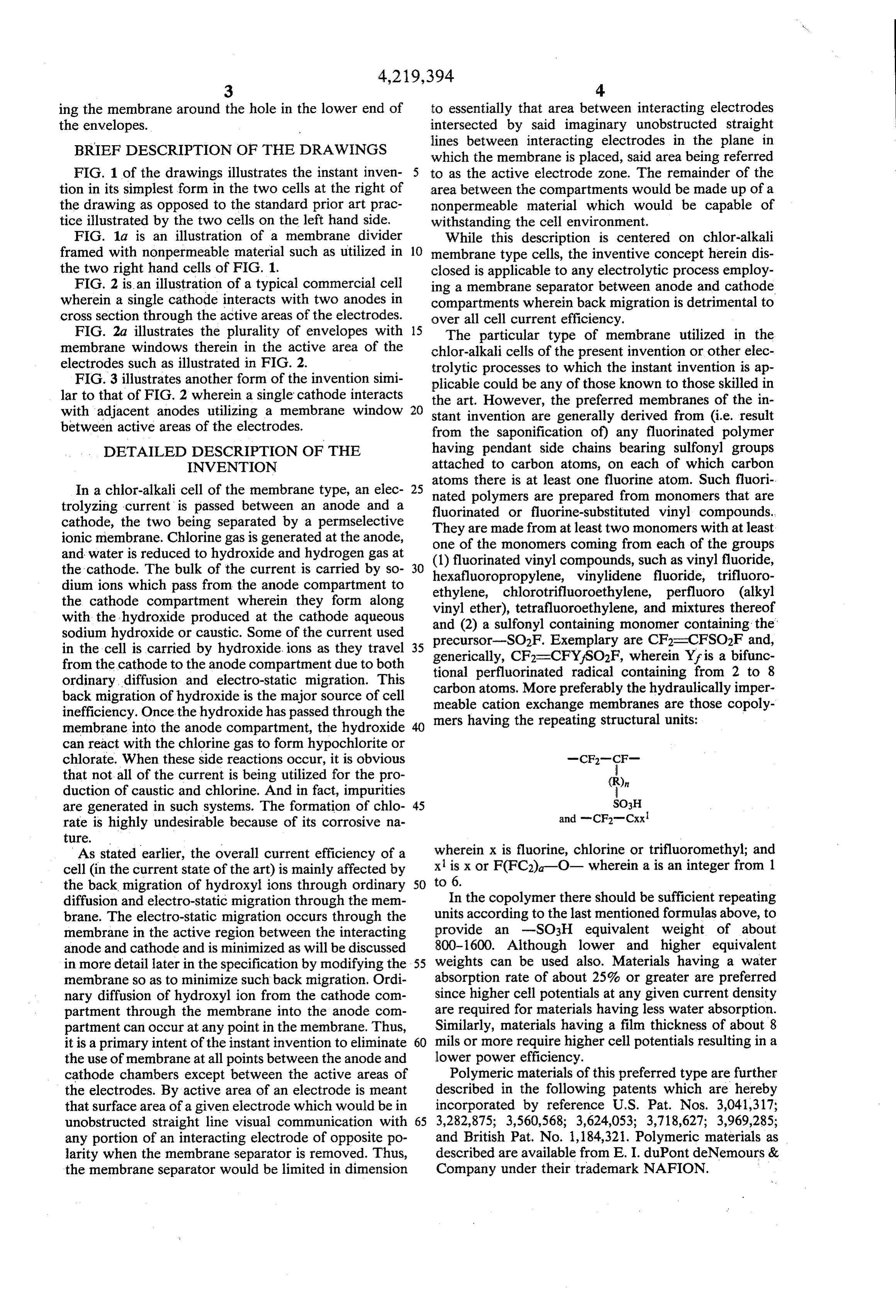
In a chlor-alkali cell of the membrane type, an elec- 25 nated polymers are prepared from monomers that are trolyzing current is passed between an anode and a fluorinated or fluorine-substituted vinyl compounds. cathode, the two being separated by a permselective They are made from at least two monomers with at least ionic membrane. Chlorine gas is generated at the anode, one of the monomers coming from each of the groups and water is reduced to hydroxide and hydrogen gas at (1) fluorinated vinyl compounds, the cathode. The bulk of the current is carried by so- 30 hexafluoropropylene, vinylidenesuch as vinyl fluoride, dium ions which pass from the anode compartment to ethylene, chlorotrifluoroethylene, fluoride, trifluoro perfluoro (alkyl the cathode compartment wherein they form along vinyl ether), tetrafluoroethylene, and mixtures thereof with the hydroxide produced at the cathode aqueous sodium hydroxide or caustic. Some of the current used and (2) a sulfonyl containing monomer containing the precursor-SO2F. Exemplary are CF2=CFSO2F and, in the cell is carried by hydroxide. ions as they travel 35 generically, CF2=CFY/SO2F, wherein Yr is a bifunc from the cathode to the anode compartment due to both tional perfluorinated radical containing from 2 to 8 ordinary diffusion and electro-static migration. This carbon atoms. More preferably the hydraulically imper back migration of hydroxide is the major source of cell meable cation exchange membranes are those copoly inefficiency. Once the hydroxide has passed through the mers having the repeating structural units: membrane into the anode compartment, the hydroxide 40 can react with the chlorine gas to form hypochlorite or chlorate. When these side reactions occur, it is obvious -CF- (Fthat not all of the current is being utilized for the pro duction of caustic and chlorine. And in fact, impurities are generated in such systems. The formation of chlo- 45 so;H rate is highly undesirable because of its corrosive na and -CF-Cxx ture.
As stated earlier, the overall current efficiency of a wherein x is fluorine, chlorine or trifluoromethyl; and cell (in the current state of the art) is mainly affected by x1 is x or F(FC2)-O- wherein a is an integer from 1 the back migration of hydroxyl ions through ordinary 50 to 6.
diffusion and electro-static migration through the mem In the copolymer there should be sufficient repeating brane. The electro-static migration occurs through the units according to the last mentioned formulas above, to membrane in the active region between the interacting provide an -SO3H equivalent weight of about anode and cathode and is minimized as will be discussed 800-1600. Although lower and higher equivalent in more detail later in the specification by modifying the 55 weights can be used also. Materials having a water membrane so as to minimize such back migration. Ordi absorption rate of about 25% or greater are preferred nary diffusion of hydroxyl ion from the cathode com since higher cell potentials at any given current density partment through the membrane into the anode com are required for materials having less water absorption. partment can occur at any point in the membrane. Thus, Similarly, materials having a film thickness of about 8 it is a primary intent of the instant invention to eliminate 60 mils or more require higher cell potentials resulting in a the use of membrane at all points between the anode and lower power efficiency.
cathode chambers except between the active areas of Polymeric materials of this preferred type are further the electrodes. By active area of an electrode is meant described in the following patents which are hereby that surface area of a given electrode which would be in incorporated by reference U.S. Pat. Nos. 3,041,317; unobstructed straight line visual communication with 65 3,282,875; 3,560,568; 3,624,053; 3,718,627; 3,969,285; any portion of an interacting electrode of opposite po and British Pat. No. 1,184,321. Polymeric materials as larity when the membrane separator is removed. Thus, described are available from E. I. duPont deNemours & the membrane separator would be limited in dimension Company under their trademark NAFION.
Page 7
The nonpermeable portion of the divider between the brane window 3 conforming to the size and shape or anode and cathode compartments contemplated by the active electrode zone between the cell compartments instant invention can be any nonconductive or imper surrounded and sealed to an impermeable member 4. meable material that can withstand the environment of FIG. 2 illustrates another form of the invention and is the particular electrolytic cell in which it is utilized. intended to show a more commercial form of the instant Typically, such impermeable materials as polyvinyl invention in a monopolar electrolytic unit 6. Basically, chloride, hard rubber, titanium or the like could be unit 6 consists of a series of six vertically arranged an used. The only criteria for selecting the impermeable odes 7 with vertically disposed cathodes 8 between material is first that it is indeed impermeable and can be each pair of anodes 7. The cathode compartments of fixedly attached to the membrane sufficiently to have an 10 such a chlor-alkali unit 6 are hydraulically isolated from economic life expectancy. Preferably, the impermeable the anode compartments by a separator 9 best illustrated portion of the cell divider would be made up of FEP or in FIG. 2a. Referring to FIG. 2a, separator 9 is primar PFA type Teflon manufactured by E. I. duPont deNe ily constructed of impermeable material and preferably mours and Company which can be shaped in the desired fluorinated ethylene propylene polymer and generally manner by methods known to those skilled in the mold 15 consists of envelopes 10 which are open topped box-like ing arts. When using the preferred impermeable Teflon members which surround each anode. The tops of each materials (hereinafter referred to as FEP and PFA), it envelope 10 are interconnected by a generally flat upper should be pointed out that an unsaponified Nafion mem surface 11 which extends out beyond envelopes 10 in all brane must be used in order to effect a good heat sealed directions so as to form a lip which is used to effect a joint so as to form a strong leak-free bond that holds up seal with the cell walls to as to completely hydraulically well during cell operation. By unsaponified Nafion isolate all the cathode chambers from the anode cham membrane is meant one in which the sulfonyl fluoride bers of unit 6. In separator 9 in the areas which lie be groups on the polymer have not yet been converted to tween active areas of electrodes, windows 12 consist of the alkali metal form. permselective membrane, preferably of the Nafion type. Likewise, should it be desired to use a surface treated 25 As in other variations of the instant invention, these Nafion type membrane wherein the sulfonyl fluoride window-like membranes are fixedly attached, prefera groups of the Nafion type membrane are reacted with bly by heat sealing, to the impermeable portion of sepa ammonia gas, an amine, polyamine, or mixtures thereof, rator 9.
such surface treatment of the Nafion type membranes When using the illustrated constructions of FIGS. 2 should be done subsequent to the heat sealing of the 30 and 2a as a chlor-alkali cell, the separator 9 is open membrane to the FEP impermeable portion of the di above anodes 7 so as to permit brine circulation and vider between the anode and the cathode compart chlorine gas release. Separator 9 is closed above the ments. cathodes which forces the hydrogen and caustic formed In the simplest form, the present invention could at the cathode to be collected through openings in the consist of a single cell having one anode and one cath 35 side of unit 9 or in the alternative separate openings ode being separated from the anode compartment by a could be cut through upper surface 11 (not shown) with liquid impermeable plastic sheet. At the active electrode the appropriate associated hardware to withdraw either areas, the plastic would be cut out and replaced with a the caustic or hydrogen formed at the cathodes. permselective membrane which would be heat sealed to FIG. 2 is also illustrative of a great many commercial the plastic sheet. Alternatively, the membrane material 40 diaphragm type chlor-alkali units. Of course when such could extend from cell wall to cell wall and all areas of a unit is a diaphragm unit, separator 9 would be re said membrane not in the active electrode zone would moved and each cathode would be coated with an as be coated with any nonpermeable material which pre bestos diaphragm. Thus, the particular design illus vents hydroxyl ion passage and can withstand the cell trated in FIGS. 2 and 2a for separator 9 represents one environment. FIG. 1 illustrates this concept in a four 45 permitting easy conversion from diaphragm to mem cell bipolar unit 1. While this is illustrated as a bipolar brane cell operation with only minor changes in the cell electrolytic cell, it could be rearranged without depart hardware. The particular dimensions and shape of the ing from the scope of the instant invention to a monopo liner can be modified to fit any given cell design. lar unit. By monopolar unit is meant one in which each As can be seen from the structure of separator 9, it cell is separate with all anodes commonly connected 50 can be easily prefabricated for quick conversion of an and all cathodes separately commonly connected. In operating commercial chlor-alkali cell of the diaphragm any event, the first two cells shown in FIG. 1 separate type to the membrane type with essentially the only the anodes and cathodes thereof with a permselective changes required would be to install a modified method membrane 2. The membrane 2 extends all the way to the of removing the hydrogen gas generated at the cath cell walls and bottom of unit 1 and is intended to indi 55 odes.
cate the normal practice envisioned in the prior art. The As has been stated earlier, the preferred permselec last two individual cells in unit 1 include permselective tive membrane is a cation exchange resin sold under the membranes 3 which are framed by an impermeable trade name Nafion. The surface of the Nafion may be membrane 4, said impermeable member effects a seal treated with ammonia gas, amines (both primary, sec with the membrane so as to completely isolate the ondary and polyamines) or mixtures thereof. Such sur anode and cathode compartments hydraulically and face treatment improves the membranes resistance to also covers all of the inactive electrode area between back migration of hydroxide through the membrane. the compartments. As illustrated, each individual cell in Among the more effective surface treatments for this unit 1 is isolated by walls 5 between each successive purpose is to surface treat with ethylene diamine prior cell. 65 to saponification of the membrane. Such surface treat FIG. a more clearly illustrates the divider used in ment, however, further embrittles a somewhat delicate the last two cells of FIG. 1 to divide the anode and material from which the membrane is made which fur cathode compartments with the permselective mem ther obviates the improvement of the instant invention.
Page 8
If the separators as shown in FIGS. 2 and 2a were con and is the only form of the Nafion which is suitable for structed entirely of such membrane material, it would heat sealing and, indeed, the only state of the polymer lead to quick failure in operation, if indeed one could be which may be used for the instant purposes. In this formulated which would remain hydraulically imper form, Nafion may be sealed to itself or to FEP type meable, since the embrittlement would undoubtedly Teflon. After heat sealing the sulfonyl fluoride form cause ruptures to occur where the membrane made membrane, the membrane is subsequently hydrolyzed in sharp angle bends or has to be stretched in the forma strong base to its final operating saponified form. If it is tion of the separator. Such deficiencies in an all mem desired to modify the membrane surface with ammonia brane separator cannot be improved by using a thicker gas, amines, polyamines, or mixtures thereof, such mod membrane material or by utilizing membrane with O ification is affected subsequent to heat sealing the Na heavy reinforcing therein because both would be detri fion membrane window in place and prior to acidifi mental to the operation of the cell and in themselves cation and/or saponification thereof. affect deterioration of the membrane and loss of current The heat sealing step itself must be accomplished at a efficiency. On the other hand, the membrane separators temperature sufficient to melt the materials used in con of the instant invention are all essentially flat sheets 15 structing the cell separators. When Nafion-FEP cell which is the shape in which they were formed and no separators are fabricated, the required temperature to further stresses need be applied to them in fabrication of affect the properheat seal is between 600-640 F. Care the separator other than to affect the heat seal between should be taken to limit the heating to the areas where the membrane windows and the surrounding imperme the seal is desired only. Heat sinks are preferably used to able FEP structure. eliminate overheating surrounding areas of membrane The Nafion type membrane when used in the practice or FEP. Typical heat sinks could be aluminum sheet of the instant invention is usually of a thickness of 1-10 material in contact with the membrane and FEP adja mils and can be fabric backed. Thinner membranes can cent the surfaces to be sealed. Another specific means to be utilized but fabrication and handling is naturally protect areas adjacent the heat seals which have been more difficult. Membranes thicker than 10 mils likewise 25 found to be most effective, is to place 0.005 inch tita can be used but are detrimental from a current effi nium shim stock over areas to be protected and this ciency standpoint. The FEP plastic portion of the sepa serves to conduct the heat rapidly away from those rators of the instant invention can be of any thickness areas resulting in no heat seal or damage beneath the which can be conveniently utilized in the particular cell metal.
configuration in which it will be used. Normally how 30 The heat seals are best obtained by placing the mate ever, an FEP plastic of approximately the thickness of rials to be heat sealed between opposed heated platens the membrane is sufficient but preferably would be in which both apply the heat to the area to be sealed and the 5-15 mill range. Of course, thicker FEP membranes supply the slight pressure required to affect a good seal. could be utilized and in fact such could be designed to With respect to pressure, any pressure can be used so contain raised portions thereon which would help posi 35 long as it is not excessive so as to result in extruding tion the anodes and cathodes with respect to the desired melted membrane and/or FEP from between the op cell geometry. : '. posed platens.
The FEP plastic or other impermeable material from In commercial practice for a monopolar cell, the cell which the majority of the separator would be made can separator has to fit very snugly over the cathode assem be formed by any conventional molding techniques. It is 40 bly so that proper gasketing and sealing can be accom preferred that complex shapes such as shown in FIG. 2 plished. For this reason, close dimensional control over that the FEP be formed by vacuum molding. But of the assembly must be maintained. Membranes of the course other methods can be used to achieve the same Nafion type expand and contract rather greatly as they result. In normal practice, a complete. FEP separator are changed through their various forms. Fortunately, would be formed as by vacuum molding. Thereafter, 45 however, these expansions and contractions of the windows would be cut into the FEP separator which membrane from initial to final form tend to cancel each would correspond to the active areas between elec other out to a great degree and for most purposes can be trodes when properly placed in an electrolytic cell. The ignored. Thus, the preferred technique is simply to size desired Nafion sheet material would then be cut to the the assembly with sulfonyl fluoride form membrane and size and shape of the active area of the related elec 50 fabricate. The membrane expands somewhat on saponi trodes and be heat sealed to the FEP separator so as to fication, expands a little more upon conversion to the close the window which has been either cut in the FEP acid form, and then shrinks back to approximately origi separator or formed therein during molding. We have nal dimensions upon conversion to the sodium form found that it is sufficient to use a ', overlap of mem during operation.
brane around the window to affect a good seal with the 55 The best mode contemplated by the inventors for FEP which will result in long and continuous operation carrying out this invention is to first fabricate the FEP when placed in a chlor-alkali electrolytic cell. cell separator having a window between the active Nafion type membrane in its final saponified form is portions of the electrodes. The FEP separator should completely inert chemically and cannot be bonded, preferably be approximately 10 mil thickness. A Nafion glued, sewn, or mechanically fastened in any simple window which is preferably 7 mil, T-12 reinforced is way. In the acid form, the membrane has already incor cut to fit the window and to overlap the window on all porated water into its structure and thus could not be sides by approximately ''. Opposed heated platens are heat sealed conveniently. Thus, in order to affect a good made to contact the overlapped area of the FEP and heat seal between Nafion and the impermeable portion membrane and the overlapped portion is heated to a of the cell divider, Nafion in the sulfonyl fluoride form 65 temperature in the range of 620-630 F. while maintain should be used. In the sulfonyl fluoride form, the Nafion ing a slight pressure with the opposed platens. The is still thermoplastic with good heat bonding properties. opposed heated platens are preferably Teflon coated to Also, the sulfonyl fluoride form of Nafion is anhydrous prevent sticking to the seals. However, if sticking is a
Page 9
problem, a thin sheet of KAPTON polyimide film (ap The cathode 15 is attached to a cathode plate 20 proximately 0.003 inch thickness) can be placed be containing bolt holes 21 which are used to bolt the tween the materials to be sealed and the platen to effec cathode into the cell, tively keep the platen from sticking to the sealing por Such a cathode as shown in FIG. 3 was utilized in the tions of the cell separator. following example.
After cooling, the seals are now complete and the EXAMPLE side of the membrane facing the cathode can now be modified by treatment with ammonia gas, amines, poly A rubber lined steel cell body was fabricated contain amines, or mixtures thereof by methods known in the O ing two anodes with an intermediate cathode. The an odes were conventional dimensionally stable anodes, prior art prior to saponification of the membrane.
The saponification of the completed assembly con i.e., titanium mesh with a Beer coating. The active area. sists of taking the membrane assembly in the sulfonyl of the anodes measured 6' by 1" by 24'. The cathode fluoride form in the surface modified form and immers was constructed as shown in FIG. 3. It consisted of a . ing same in a solution of 60% dimethylsulfoxide, 40% 15 steel body with 0.06' wide nickel parallel plates. The water, and 13% by weight KOH or NaOH at a tempera parallel plates had an area of 6' by 24' on each side and ture of 80-90 C, for approximately 2 hours. The assem were separated by approximately ". The separator was bly is then removed, rinsed with distilled water, and constructed from 10 mil FEP and two pieces of un saponified Nafion permselective ionic membrane mea soaked in dilute hydrochloric acid (about 5%) at 50-60
C. until ready for use. This procedure assures the pres suring 6' by 24'. The membrane was sealed to the FEP ence of ionic species within the membrane so that an 20 separator by pressing the same together and heating them to a temperature of 620-630 F. After heat sealing easy start-up is achieved. the unsaponified Nafion windows to the FEP separator, The sealing of backed or fabric reinforced membrane the to itself is made more reliable by the use of lengths of' hourmembranewith a was saponified by contacting it for one dimethylsulfoxide caustic solution at 95 C.
wide sulfonyl fluoride form Nafion film. By placing 25 followed by a one hour treatment with 5% HCl at 90' such a strip of Nafion film between the backed rein C. After assembly of the cell, the membrane area went forced side of the membrane window and the adjacent through its "break in' period by being operated at 1 reinforced membrane, improved contact is obtained ASI for 3 days. During this break in period, the voltage between the backed membranes being joined and a ranged from 3.42 to 3.53 volts at a cell temperature of better bond is accomplished since the sandwiched strip 30 80 C. and at caustic concentrations of 460-470 grams of Nafion film can flow to fill gaps and voids caused by per liter. The above constructed cell with a 'anode to the reinforcing fabric. This procedure is not necessary cathode electrode gap was operated for 42 straight days when bonding FEP or unbacked film to fabric rein at 2 ASI (approximately 550 amps) and no major diffi foced film since the flow properties of these materials culties were encountered and the separator remained under heat and pressure are adequate to insure good 35 leak tight throughout. Cell temperatures during the run seals in and of themselves. leveled out at 88 C. with cell voltages of 4.30-440 Another aspect of the instant invention is that it now volts. The routine current efficiency ranged from enables the construction of a monopolar type chlor 71-75% at caustic concentrations of 510-540 grams per alkali cell of the membrane type which for the first time liter. The membrane used in this example was a 7 mil can be commercially operational while utilizing a less 40 T-12 fabric reinforced 1200 equivalent weight Nafion capital intensive design than is required by the currently membrane and the FEP had a thickness of 10 mills. existing bipolar chlor-alkali cells. In addition to the easy We claim:
replacement of electrodes in the monopolar arrange 1. A method of improving current efficiency in a ment, simplified gas take off means can be employed chlor-alkali cell of the membrane type which comprises which result in appreciable capital investment savings. 45 limiting back-migration of hydroxyl ions through the Operation of the electrolytic cells contemplated by membrane divider by limiting the membrane portion of the instant invention are at their normal current density, the divider to a size and shape conforming to substan temperature and catholyte and anolyte concentrations. tially the active electrode zones between interacting Typically, in a chlor-alkali cell the current density electrodes, said membrane portion of the divider being would range from 1 to 3 ASI at a cell operating temper 50 positioned substantially directly between said interact ature of approximately 90-95' C. With respect to con ing electrodes in said active electrode zones and having centrations of anolyte and catholyte, it is preferred that the remaining portion of the divider being impervious the anolyte be a saturated brine solution and the catho to hydroxyl back-migration.
lyte contain approximately 520–560 grams per liter 2. The method of claim 1 wherein the membrane caustic. 55 portion of the divider between anolyte and catholyte FIG. 3 is another embodiment of the instant inven chambers is a fluorinated polymer containing pendant tion. Here is shown a cathode 15 which is intended to be side chains containing sulfonyl groups which are at operational between two related anodes not shown. An tached to carbon atoms which have at least one fluorine FEP form 16 is shaped like the cathode 15 and is de atom attached thereto and the nonpermeable portion of signed to slide over the cathode completely enclosing 60 the divider is fluorinated ethylene propylene or per the same. FEP form 16 has Nafion windows 17 on both fluoroalkoxy modified polytetrafluoroethylene. sides of the FEP form which have been heat sealed 3. In a chlor-alkali electrolytic cell of the membrane thereto and are sized and shaped to conform to the type wherein the anolyte and catholyte are separated by active area of the electrodes. The particular design a hydraulically impermeable membrane, the improve illustrated in FIG. 3 consisted of a steel cathode body 18 65 ment comprising limiting the hydraulically imperme connected to parallel nickel plates in the active cathode able membrane portion of the divider between anolyte area 19. The FEP form 16 after being slid over the and catholyte chambers to the active electrode zones cathode is sealed therein by gasketing. while all other areas of the divider are nonpermeable so
Page 10
as to minimize back-migration of undesirable ions and shape conforming to substantially the active electrode maximize current efficiency. zones between said interacting electrodes and said 4. The electrolytic cell of claim 3 wherein the mem membrane windows being positioned substantially di brane portion of the divider between anolyte and catho rectly between said interacting electrodes in said active lyte chambers is a fluorinated polymer containing pen electrode zones, each said open-top boxlike means being dant side chains containing sulfonyl groups which are interconnected at their tops by a substantially horizon attached to carbon atoms which have at least one fluo tal hydraulically impermeable member which extends rine atom attached thereto and the nonpermeable por outwardly from the top of each boxlike means as to tion of the divider is fluorinated ethylene propylene or form a seal with the cell and adjacent boxlike means to perfluoroalkoxy modified polytetrafluoroethylene. 10 completely separate the anolyte and catholyte cham 5. In a chlor-alkali electrolytic cell wherein one or bers.
more cathodes each interact electrolytically with a 8. The electrolytic cell of claim 7 wherein the men plurality of anodes and wherein anolyte and catholyte brane portion of the divider between anolyte and catho chambers are separated by a hydraulically impervious lyte chambers is a fluorinated polymer containing pen divider, the improvement comprising a divider shaped 15 dant side chains containing sulfonyl groups which are to closely fit each such cathode made from an impervi attached to carbon atoms which have at least one fluo ous, nonconductive material having windows therein rine atom attached thereto and the nonpermeable por consisting of hydraulically impervious membrane, said tion of the divider is fluorinated ethylene propylene or membrane windows being of a size and shape conform perfluoroalkoxy modified polytetrafluoroethylene. ing to substantially the area of the active electrode 20 9. A method of making a cell divider for an electro zones of said interacting electrodes and said membrane windows being positioned substantially directly be lytic cell of the membrane type comprising heat sealing at a temperature of in excess of approximately 600 F. a tween said interacting electrodes. membrane window to an impervious fluorinated ethyl 6. The electrolytic cell of claim 5 wherein the mem ene brane portion of the divider between anolyte and catho 25 atingpropylene member which when in place in an oper cell divides the anolyte and catholyte chambers, lyte chambers is a fluorinated polymer containing pen said membrane window comprising a film of fluorinated dant side chains containing sulfonyl groups which are polymer containing pendant side chains containing sul attached to carbon atoms which have at least one fluo fonyl fluoride rine atom attached thereto and the nonpermeable por atoms which have at least groups which are attached to carbon one fluorine atom attached tion of the divider is fluorinated ethylene propylene or 30 thereto, and, after heat sealing, perfluoroalkoxy modified polytetrafluoroethylene. saponifying said mem 7. In a monopolar chlor-alkali cell having a plurality brane with an alkali metal hydroxide, said membrane of essentially vertically arranged parallel electrodes of windows being of a size and shape conforming to sub one polarity extending downward into the cell with an stantially the active electrode zones of said interacting essentially vertically arranged parallel electrode of op 35 electrodes and said membrane windows being posi posite polarity extending upwardly within the cell be tioned substantially directly between said interacting tween each adjacent pair of downwardly extending electrodes in said active electrode zones. electrodes, the improvement comprising a divider sepa 10. A method as stated in claim 9 wherein the cathode rating the anolyte and catholyte chambers, said divider facing surface of the membrane window is modified by consisting in part of open-top boxlike means of imper contacting same with at least one compound selected meable, nonconductive material enveloping each down from the group consisting of ammonia gas, amines, and wardly extending electrode and having window-like polyamines after heat sealing is completed and before openings therein of hydraulically impermeable mem saponification is initiated. k k k k k brane, said membrane windows being of a size and
Provenance
- Collection
- Cited prior art
- Original PDF
- patentimages.storage.googleapis.com →
- Filed
- 1978-03-22
- Pages
- 10
- Method
- pdftotext (the PDF's own text layer) + pdftoppm 300dpi page scans
- Source
- Google Patents bibliographic record
- Granted
- 1980-08-26
- Inventors
- Andrew D. Babinsky; Charles J. Hora; Edward J. Peters; Wayne P. Zeman; Diamond Shamrock Corp
- Transcribed from
- patentimages.storage.googleapis.com →