patent · US4376427
Engine air/fuel ratio control system with both normal idling and idle up idling capability
15 March 1983
Page 1 — bibliographic record
United States Patent (19) (11) 4,376,427 Mizuno (45) Mar. 15, 1983 (54) ENGINE AR/FUELRATO CONTROL (57) ABSTRACT
SYSTEM WITH BOTH NORMAL, DLNG
AND OLE UPOLNG CAPABILITY An engine includes a three way catalytic converter in its exhaust system, and a carburetor whose throttle 75) Inventor: Kisaburo Mizuno, Aichi, Japan valve has a normal and an idle up idling position, se 73) Assignee: Toyota Jidosha Kogyo Kabushiki lected between by an idle up device. A device for weak Kaisha, Aichi, Japan ening the air/fuel ratio of the mixture in the engine (21) Appl. No.: 321,191 intake system only functions when no oxygen is de tected in the engine exhaust system by an oxygen sen 22 Filed: Nov. 13, 1981 sor. A means for supplying enough secondary air into (30) Foreign Application Priority Data the exhaust system upstream of the oxygen sensor to make the exhaust gases leaner than stoichiometric func
Nov. 20, 1980 (JP) Japan ................................ 55-164277 tions according to supply of a controlling vacuum. A 51) Int. C. ............................................. F02D 33/00 first vacuum take out port is provided in the throat of 52 U.S.C. ...................................... 123/339; 60/290; the carburetor at a position downstream of the throttle 60/293; 123/344; 123/589 valve when it is in the normal idling position and up 58) Field of Search ............... 123/339, 341,585, 589, stream of it when it is opened a little from the normal 123/344; 60/290,293 idling position. A second vacuum take out port is pro (56) References Cited vided in the throat at a position downstream of the throttle valve when it is in the idle up idling position
3,906,723 9/1975 Matumoto et al.................. 60/290 up idling position. A vacuum switching system supplies 4,087,965 5/1978 Thornburgh ...... ... 60/290 vacuum from either the first or second take out port to 4,165,61 i 8/1979 Ishikawa ............ ... 60/293 the secondary air supplying means as controlling vac 4,192,140 .3/1980 Yamashita et al. ................. 123/589 uum, according as idle up is being not performed, or is Primary Examiner-William A. Cuchlinski, Jr. being performed, respectively. Attorney, Agent, or Firm-Stevens, Davis, Miller &
Mosher 13 Claims, 4 Drawing Figures
IDLE up
AUXARY
AIRCONTROL
DEVICE
Page 2
Drawing sheet — no readable text.
Page 3
Drawing sheet — no readable text.
Page 4
Drawing sheet — no readable text.
Page 5
Drawing sheet — no readable text.
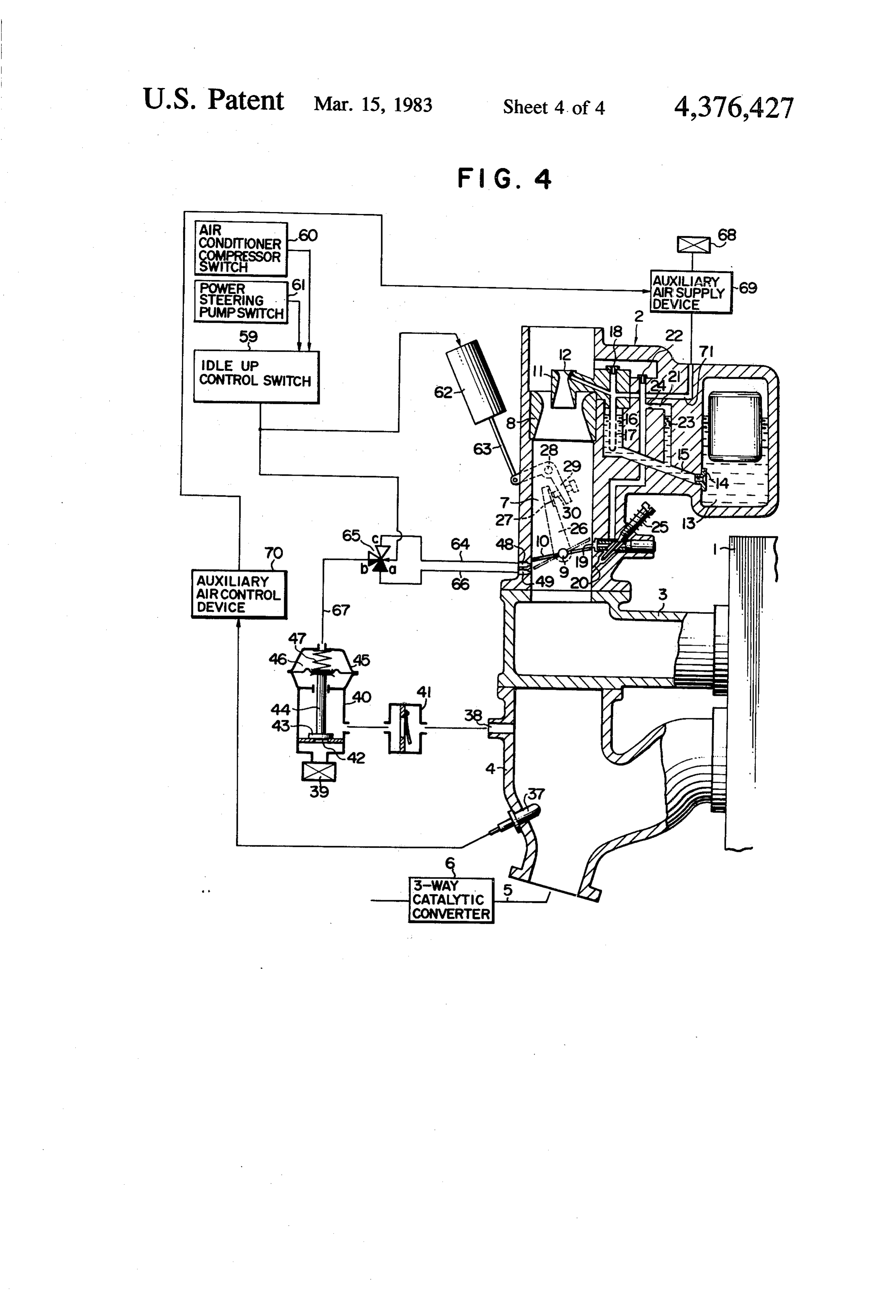
Page 6
the stoichiometric air/fuel ratio. Conventionally, the
ENGINEAR/FUEL RATO CONTROL SYSTEM extra air can either be added directly into the intake WITH BOTH NORMAL EDLING AND IDLE UP manifold of the engine, downstream of the carburetor; DLING CAPABILITY or can be provided into a passage of the carburetor, as an additional amount of bleed air to be mixed with the
BACKGROUND OF THE INVENTION fuel being provided by the carburetor, in a perse well The present invention relates to the field of air/fuel known fashion. In either case, by feedback control per ratio control devices for internal combustion engines formed by the extra air control device based upon the such as those used for automotive vehicles, and more 10 signal from the oxygen sensor, the air/fuel ratio of the particularly relates to the field of such air/fuel ratio air-fuel mixture provided into the cylinders of the inter control devices for engines which are equipped with nal combustion engine can be satisfactorily controlled carburetors in their intake systems and three way cata to be substantially the stoichiometric air/fuel ratio, and lytic converters in their exhaust systems. thereby the air/fuel ratio of the exhaust gases passing Three way catalytic converters for internal combus into the three way catalytic converter can be satisfacto tion engines are per se well known in various different 15 rily maintained within a narrow range about the stoi forms. Such a three way catalytic converter is capable chiometric condition.
of converting HC, CO, and other products of incom This kind of prior art feedback system is effective, plete combustion in the hot exhaust gases of the internal and presents no problems for drivability of the vehicle combustion engine into harmless end products by an incorporating the internal combustion engine under the oxidizing reaction, and also of simultaneously convert 20 engine load condition; but it is not satisfactory for en ing nitrogen oxides (so called NOx) in the exhaust gases gine idling operation. In fact, such a feedback system as into harmless end products by a reducing reaction, pro outlined above causes surging and stumbling of the vided that the air/fuel ratio of the exhaust gases passing internal combustion engine to occur during idling, and into said catalytic converter is maintained within a stable idling operation becomes quite impossible. rather narrow range about the stoichiometric condition. 25 In the prior art, a system that has been employed to If, however, the air/fuel ratio of the exhaust gases pass ing into said catalytic converter wanders towards the overcome this problem has been developed as follows. Based upon the realization that during idling operation lean side stoichiometric, then although the above de the production of nitrogen oxides by the internal com tailed oxidizing reaction for converting HC, CO, and other products of incomplete combustion in the hot 30 bustion engine is not very considerable, and as a practi exhaust gases of the internal combustion engine into residues ofonly cal matter the production of HC, CO, and other harmless end products continues, the reducing reaction threat to theincomplete combustion presents a major for converting nitrogen oxides in the exhaust gases into conceived of cleanliness of the atmosphere, it has been to operate the engine during engine idling harmless end products will substantially cease; and, if the air/fuel ratio of the exhaust gases passing into said 35 condition by supplying thereto via the intake system an catalytic converter wanders towards the rich side of air-fuel mixture of air/fuel ratio substantially richer stoichiometric, then although the reducing reaction for than stoichiometric, and then to inject a substantial converting nitrogen oxides in the exhaust gases of the amount of secondary air into the exhaust system of the internal combustion engine into harmless end products engine, upstream of the three way catalytic converter, continues, the oxidizing reaction for converting HC, in sufficient amount to render the air/fuel ratio of the CO, and other products of incomplete combustion in exhaust gases definitely leaner than stoichiometric at the hot exhaust gases into harmless end products will the time that the exhaust gases enter the three way substantially cease. catalytic converter. As a result, as noted above, the It is possible to control the air/fuel ratio of the ex oxidizing reaction for converting HC, CO, and other haust gases passing into the three way catalytic con 45 products of incomplete combustion in the hot exhaust verter within a narrow range about the stoichiometric gases of the internal combustion engine into harmless condition by controlling the air/fuel ratio of the air-fuel end products continues satisfactorily, and although the mixture being supplied to the internal combustion en reducing reaction for converting nitrogen oxides in the gine through its intake system within a narrow range exhaust gases into harmless end products will substan about the stoichiometric condition, and therefore con 50 tially cease, this will not provide any great problem in ventionally many different sorts of fuel/air ratio control practice, since as explained above the amounts of nitro systems have heretofore been proposed which have as gen oxides currently being produced are rather small. their goal maintaining the air/fuel ratio of the air-fuel Further, because the air/fuel ratio of the idling air-fuel mixture being supplied to the internal combustion en mixture being supplied to the internal combustion en gine close to the stoichiometric condition. 55 gine is substantially richer than stoichiometric, stum A typical such prior art system has an oxygen sensor bling, surging, stalling, and irregular operation of the fitted to the exhaust manifold of the internal combustion internal combustion engine during idling are substan engine, upstream of the three way catalytic converter, tially prevented.
so as to sense the presence of oxygen in the exhaust A problem that has arisen with this prior art concept, gases therein. The signal from this oxygen sensor is then in adapting it to actual automobiles of the sort that are sent to a device which provides extra air into the intake being produced nowadays, is that it is common at the system of the engine. In this case, the basic air/fuel ratio present time for carburetors of internal combustion of the air-fuel mixture provided by the carburetor of the engines for automobiles to be provided with so called internal combustion engine is set to be rather on the rich idle up devices, which increase the idling speed of the side of stoichiometric, and thus by addition of a proper 65 internal combustion engine in response to increased amount of extra air to the intake system the air/fuel idling load on the engine. For instance, conventionally ratio of the air-fuel mixture provided to the internal and commonly engine idle up is performed when an air combustion engine may be controlled to be substantially conditioner compressor is required to be operated dur
Page 7
ing engine idling operation. Various other factors may and a three way catalytic converter, which is conve also cause engine idle up to be performed, such as the niently integrated with the electrical actuation of the operation of a power steering pump, or the like. The idle up of the carburetor, adaptation of the above concept of air/fuel ratio control It is a yet further object of the present invention to to these cases has not been straightforward. provide an air/fuel ratio control system as detailed SUMMARY OF THE INVENTION above for an internal combustion engine equipped with a carburetor with idle up capability and a three way
Accordingly, it is the primary object of the present catalytic converter, which injects additional primary air invention to provide an air/fuel ratio control system for into the intake manifold downstream of the carburetor. an internal combustion engine equipped with a carbure O It is a yet further object of the present invention to tor with idle up capability and a three way catalytic provide an air/fuel ratio control system for an internal converter, which can provide smooth idling operation combustion engine equipped with a carburetor with idle of the internal combustion engine, both during the non up capability and a three way catalytic converter, idle up idling engine operational condition and also which injects additional primary air into the carburetor during the idle up idling engine operational condition. 15 as additional bleed air.
It is a further object of the present invention to pro According to the present invention, these and other vide an air/fuel ratio control system for an internal objects are accomplished by, for an internal combustion combustion engine equipped with a carburetor with idle engine comprising an exhaust system and a fuel intake up capability and a three way catalytic converter, in passage system comprising a carburetor which con which the air/fuel ratio of the exhaust gases of the inter 20 prises an intake throat, a throttle valve mounted in said nal combustion engine is kept near stoichiometric when intake throat, and an idle up device which selectively the engine is not idling, but in which the air/fuel ratio of acts on said throttle valve so as to control its most the exhaust gases is kept substantially leaner than stoi closed position to be either a first idling position near its chiometric when the engine is idling, both in the idle up fully closed position or a second idle up idling position idling mode and in the non idle up idling mode. 25 slightly more open that said first idling position; said It is a further object of the present invention to pro carburetor in its basic operational mode tending to de vide an air/fuel ratio control system for an internal liver an air/fuel mixture richer than stoichiometric: an combustion engine equipped with a carburetor with idle air/fuel ratio control system, comprising: (a) an oxygen up capability and a three way catalytic converter, in sensor for detecting the concentration of oxygen in the which the engine is operated with an air-fuel mixture 30 exhaust gases in said exhaust system; (b) a means for whose air/fuel ratio is substantially the stoichiometric adjusting the air/fuel ratio of the air/fuel mixture being one when the engine is not idling, but in which the supplied to the engine through said fuel intake passage engine is operated with an air-fuel mixture whose air/f. system towards the leaner, which receives the signal uel ratio is substantially richer than stoichiometric, dur from said oxygen sensor, and which functions only ing both the idle up idling mode, and during the non idle 35 when said oxygen sensor is detecting no oxygen in the up idling mode. exhaust gases in said exhaust system; (c) a means for It is a further object of the present invention to pro supplying a flow of secondary air into said exhaust vide an air/fuel ratio control system for an internal system during idling engine operation, upstream of said combustion engine equipped with a carburetor with idle oxygen sensor, in a flow amount sufficient to render the up capability and a three way catalytic converter, exhaust gases in said exhaust system leaner than stoi which operates in the above described feedback fashion chiometric, said means thus supplying secondary air to keep the air/fuel ratio of the air-fuel mixture supplied when and only when it receives supply of a controlling to the engine near the stoichiometric one when the vacuum; (d) a first vacuum takeout port formed at a internal combustion engine is operating in a load bear point in said intake throat which is downstream of said ing operational condition, but in which the feedback 45 throttle valve when said throttle valve is in said first operation is interrupted when the internal combustion idling position but which is upstream of said throttle engine is put into the idling state, whether this be the valve when said throttle valve is opened a slight amount idle up idling state or the non idle up idling state, and from said first idling position; (e) a second vacuum instead secondary air is commenced to be supplied into takeout port formed at a point in said intake throat the exhaust system of the engine. 50 which is downstream of said throttle valve when said It is a further object of the present invention to pro throttle valve is in said second idle up idling position but vide an air/fuel ratio control system for an internal which is upstream of said throttle valve when said combustion engine equipped with a carburetor with idle throttle valve is opened a slight amount from said sec up capability and a three way catalytic converter, ond idle up idling position; and (f) a vacuum switching which prevents stumbling and stalling of the internal 55 system, which provides supply of vacuum from said combustion engine during the idling state, whether this first vacuum take out port to said means for supplying be the idle up idling state or the non idle up idling state. secondary air as said controlling vacuum when said idle It is a further object of the present invention to pro up device is controlling the most closed position of said vide such an air/fuel ratio control system as detailed throttle valve to be said first idling position, and which above for an internal combustion engine equipped with 60 provides supply of vacuum from said second vacuum a carburetor with vacuum actuated idle up capability take out port to said means for supplying secondary air and a three way catalytic converter, which is conve as said controlling vacuum when said idle up device is niently integrated with the vacuum actuation of the idle controlling the most closed position of said throttle up of the carburetor. valve to be said second idle up idling position. It is a yet further object of the present invention to 65 According to such a structure, when no idle up is provide such an air/fuel ratio control system as detailed being performed by said idle up device and the most above for an internal combustion engine equipped with closed position of said throttle valve is said first idling a carburetor with electrically actuated idle up capability position, then said vacuum switching system provides
Page 8
vacuum from said first vacuum take out port to said switching valve with a first, a second, and a third port, secondary air supplying means as controlling vacuum, a one way valve, a vacuum conduit, and a throttling so that said secondary air supplying means only supplies element; said second and said third ports of said electro secondary air when said throttle valve is in said first magnetic switching valve being communicated to idling position, otherwise during non idling operation of gether when said electromagnetic switching valve is the engine providing no secondary air so that feedback not supplied with actuating electrical energy, and said action of said air/fuel ratio adjusting means based upon first and said second ports of said electromagnetic the signal from said oxygen sensor keeps the air/fuel switching valve being communicated together when ratio of the air-fuel mixture supplied to the engine near said electromagnetic switching valve is supplied with stoichiometric; and, when idle up is being performed by 10 actuating electrical energy; said electromagnetic said idle up device and the most closed position of said switching valve being supplied with said electrical sig throttle valve is said second idling position, then said nal as supply of actuating electrical energy; said third vacuum switching system provides vacuum from said port of said electromagnetic switching valve being second vacuum take out port to said secondary air sup communicated to atmosphere; said first port of said plying means as controlling vacuum, so that said sec 15 electromagnetic switching valve being communicated ondary air supplying means only supplies secondary air to said second vacuum take out port; and said second when said throttle valve is in said second idling position, port of said electromagnetic switching valve being otherwise during non idling operation of the engine communicated to said vacuum actuator of said idle up providing no secondary air so that again feedback ac device and also being communicated via said one way tion of said air/fuel ratio adjusting means based upon 20 valve against its direction of transmitting fluid to a first the signal from said oxygen sensor keeps the air/fuel end of said conduit, the other end of said conduit being ratio of the air-fuel mixture supplied to the engine near communicated to said means for supplying a flow of stoichiometric. secondary air into said exhaust system during idling Further, according to a particular aspect of the pres engine operation so as to supply said controlling vac ent invention, these and other objects are more particu 25 uum thereto; an intermediate part of said conduit being larly and concretely accomplished by such an air/fuel also communicated via said throttling element to said ratio control system as described above, wherein said first vacuum take out port.
means for adjusting the air/fuel ratio of the air/fuel According to such a structure, when no idle up is to mixture being supplied to the engine through said fuel be performed and said electric control device is not intake passage system towards the leaner injects air into 30 outputting any electrical signal to said electromagnetic said intake passage system downstream of said carbure switching valve, then vacuum at said first vacuum take tor. out port is transmitted via said throttling element to said According to such a structure, this additional air conduit and thereby to said means for supplying second mixes with the air-fuel mixture which has been pro ary air as said controlling vacuum, not escaping duced by the carburetor so as to produce the air-fuel 35 through said one way valve due to its one way action, mixture which is combusted in the engine, the air/fuel while vacuum at said second vacuum take out port is ratio of which is kept within a narrow range about the not transmitted anywhere, and further said vacuum stoichiometric condition by the aforesaid feedback ac actuator is communicated to said second port of said tion of said air/fuel ratio adjusting means. electromagnetic switching valve and thence to said Alternatively, according to a particular aspect of the 40 third port thereof and thence to atmosphere, thus not present invention, these and other objects may be more being actuated and thus not performing carburetor idle particularly and concretely accomplished by such an up; but on the other hand, when idle up is to be per air/fuel ratio control system as first described above, formed and said electric control device is outputting an said carburetor being formed with an auxiliary air bleed electrical signal to said electromagnetic switching passage, wherein said means for adjusting the air/fuel 45 valve, then vacuum at said second vacuum take out port ratio of the air/fuel mixture being supplied to the engine is transmitted to said first port of said electromagnetic through said fuel intake passage system towards the switching valve, whence it is transmitted to said second leaner injects air into said auxiliary air bleed passage. port thereof, whence it is transmitted to said vacuum According to such a structure, this additional air actuator to actuate it and to perform carburetor idle up mixes within the carburetor with the air-fuel mixture 50 and is also transmitted via said one way valve to said which is being produced by the carburetor so as to conduit which transmits it to said means for supplying produce the air-fuel mixture which is combusted in the secondary air as said controlling vacuum, not mean engine, the air/fuel ratio of which is kept within a nar while substantially leaking out through said first vac row range about the stoichiometric condition by the uum take out port and being attenuated due to the pro aforesaid feedback action of said air/fuel ratio adjusting 55 vision of said throttling element. eaS Alternatively, according to a particular aspect of the Further, according to a particular aspect of the pres present invention, these and other objects may be yet ent invention, these and other objects are yet more more particularly and concretely accomplished by such particularly and concretely accomplished by such an an air/fuel ratio control system of either of the particu air/fuel ratio control system of either of the particular lar sorts described above, for an internal combustion sorts described above, for an internal combustion en engine wherein said idle up device comprises an electric gine wherein said idle up device comprises a vacuum actuator which when supplied with actuating electrical actuator which when supplied with vacuum moves a energy moves a stop against which said throttle valve stop against which said throttle valve abuts in its idling abuts in its idling position in the direction of increasing position in the direction of increasing idling speed, and 65 idling speed, and an electric control device which dis an electric control device which despatches an electri patches an electrical signal to said electric actuator cal signal when idle up is to be performed: wherein said when idle up is to be performed: wherein said vacuum vacuum switching system comprises an electromagnetic switching system comprises an electromagnetic switch
Page 9
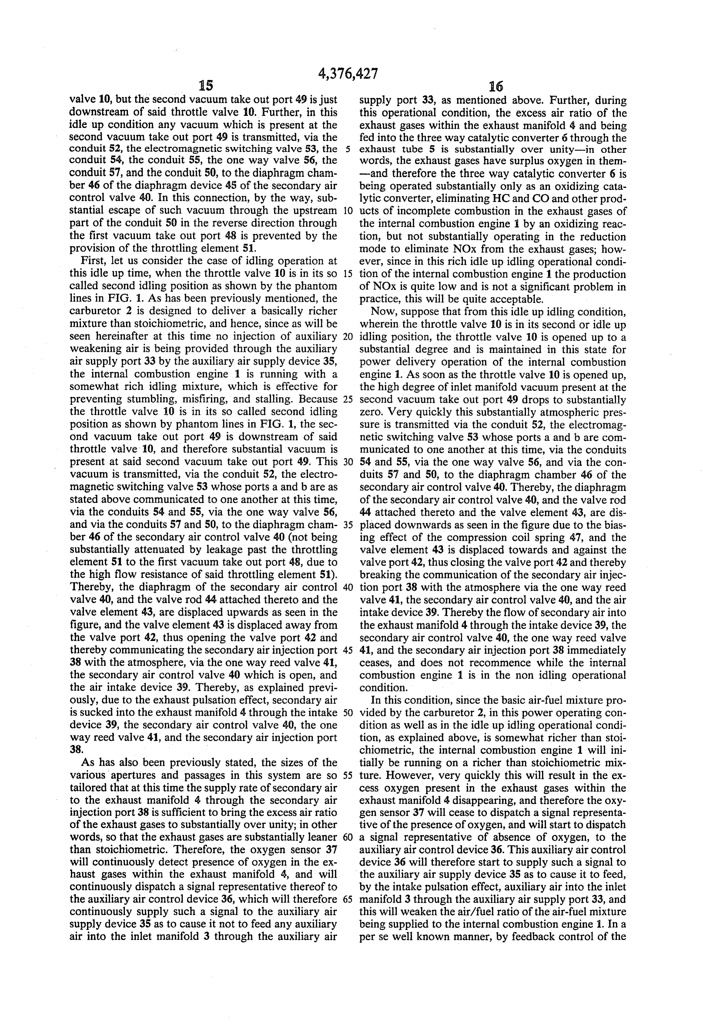
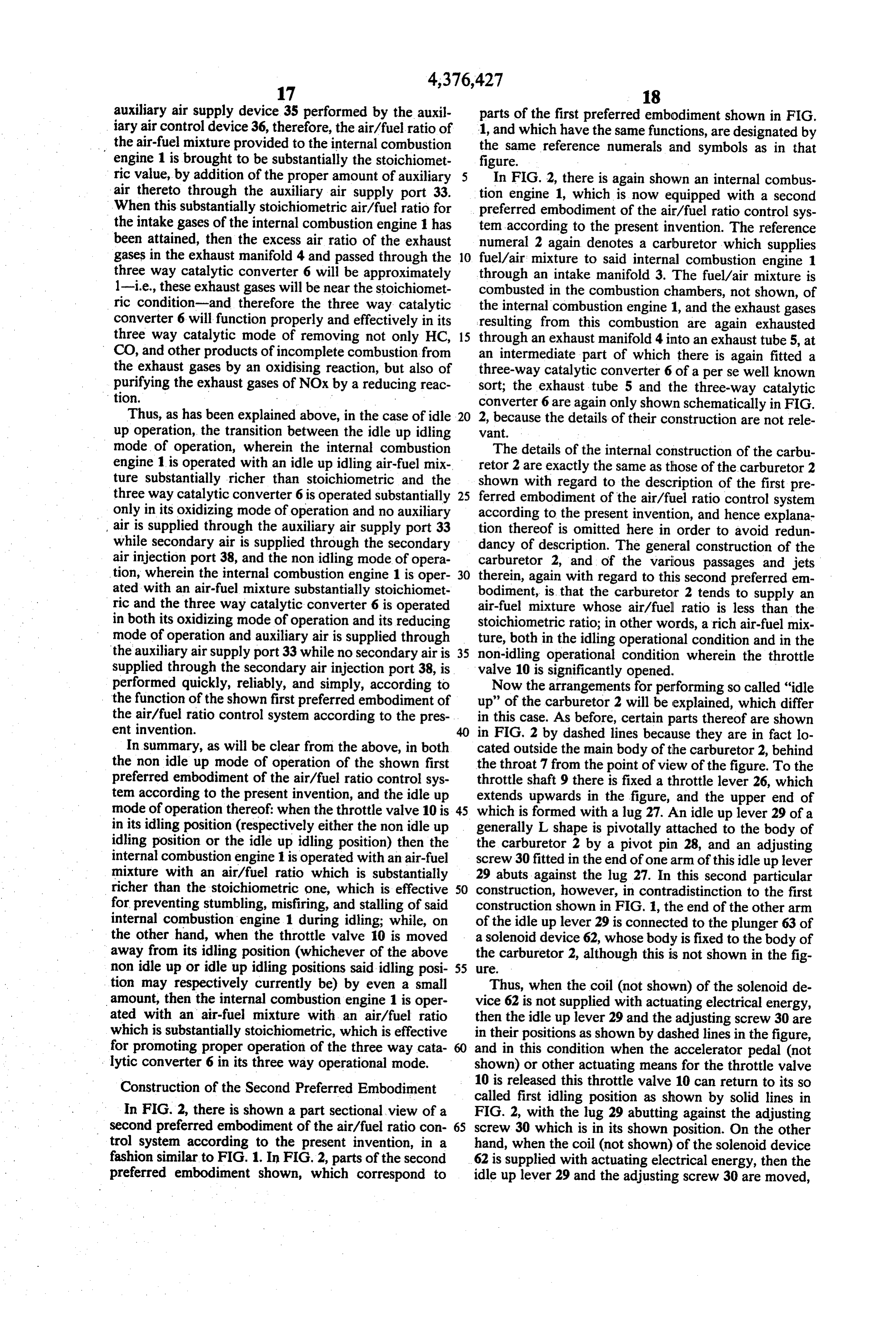
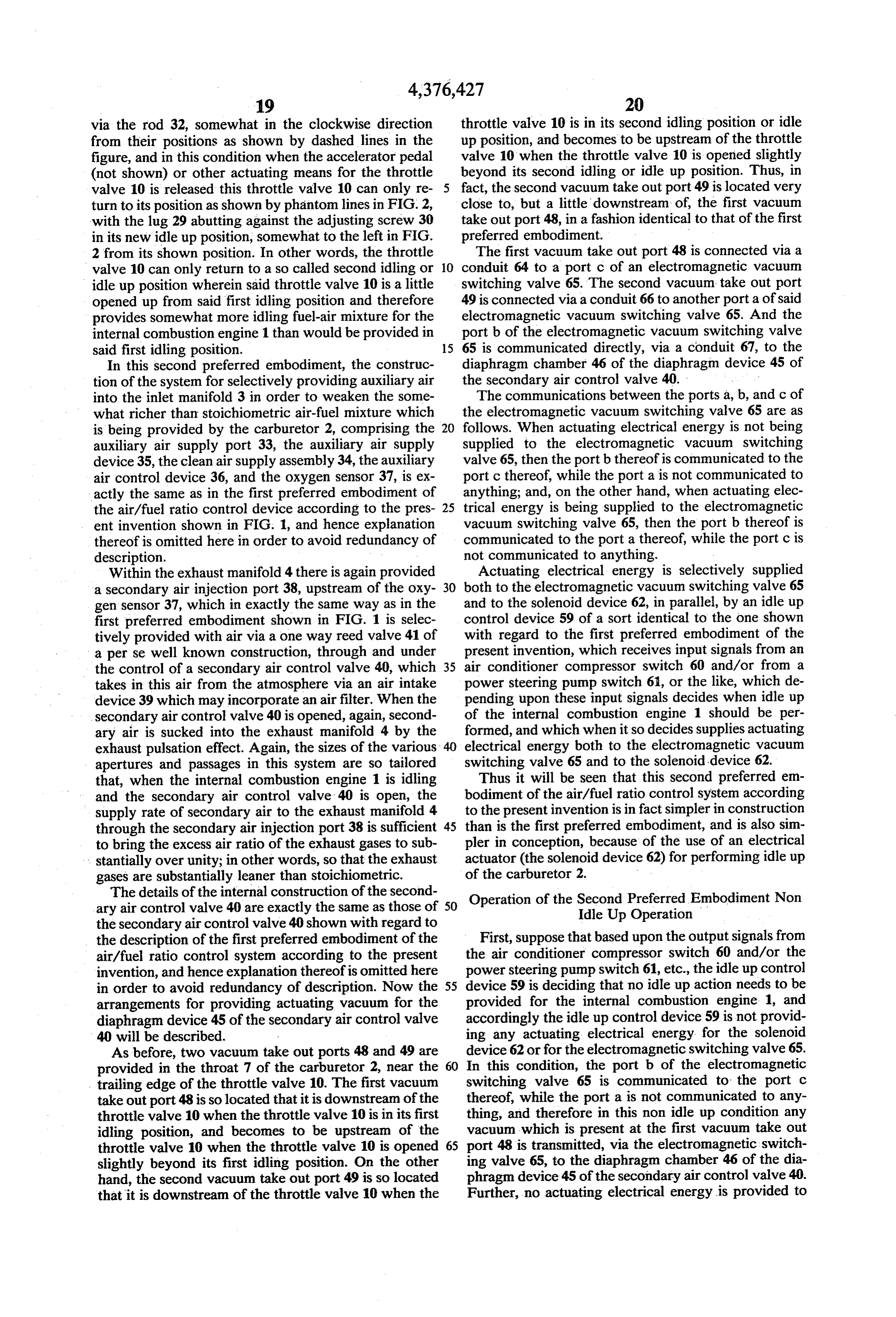
ing valve with a first, a second, and a third port; said bodiment of the present invention as fitted to this inter second and said third ports of said electromagnetic nal combustion engine;
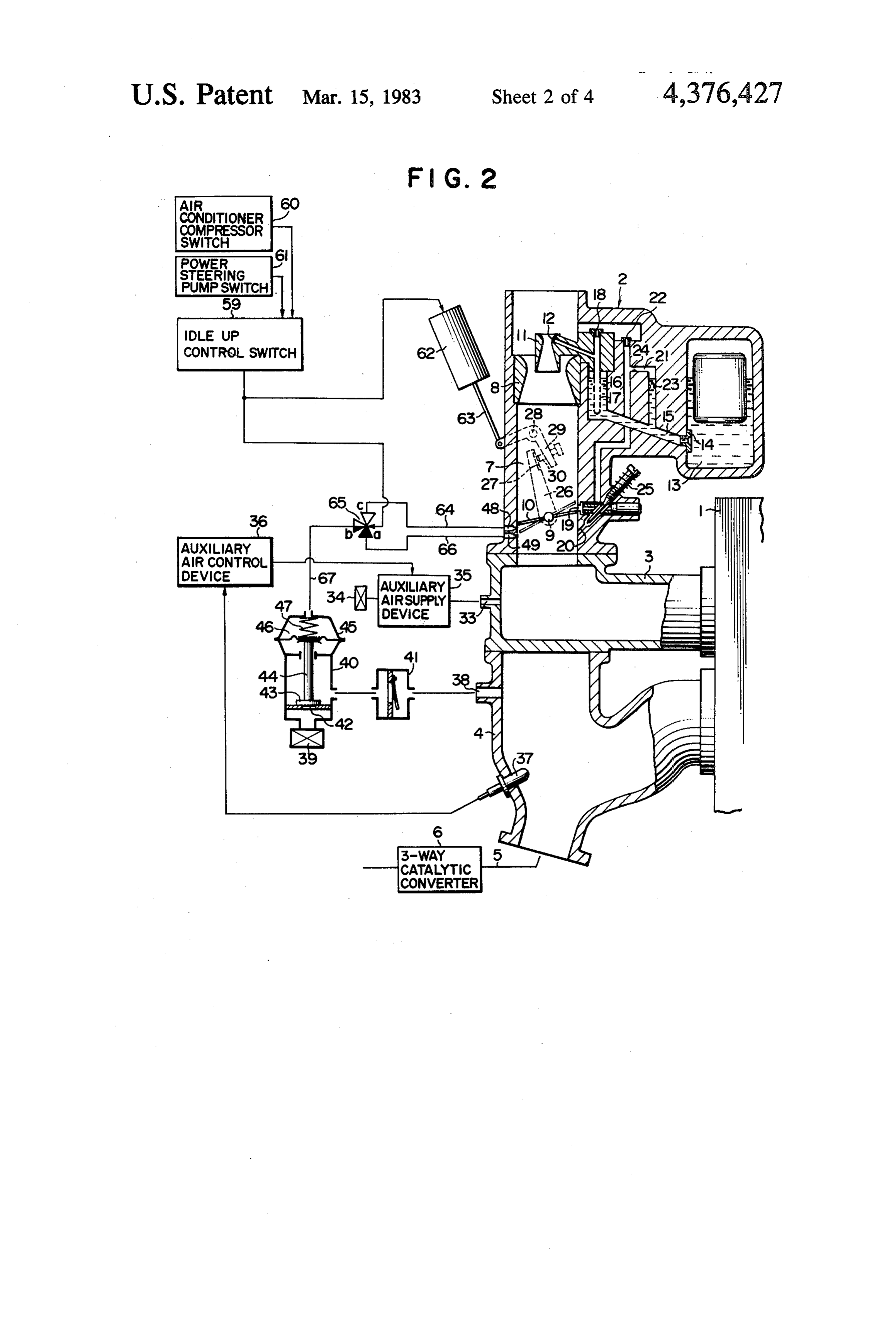
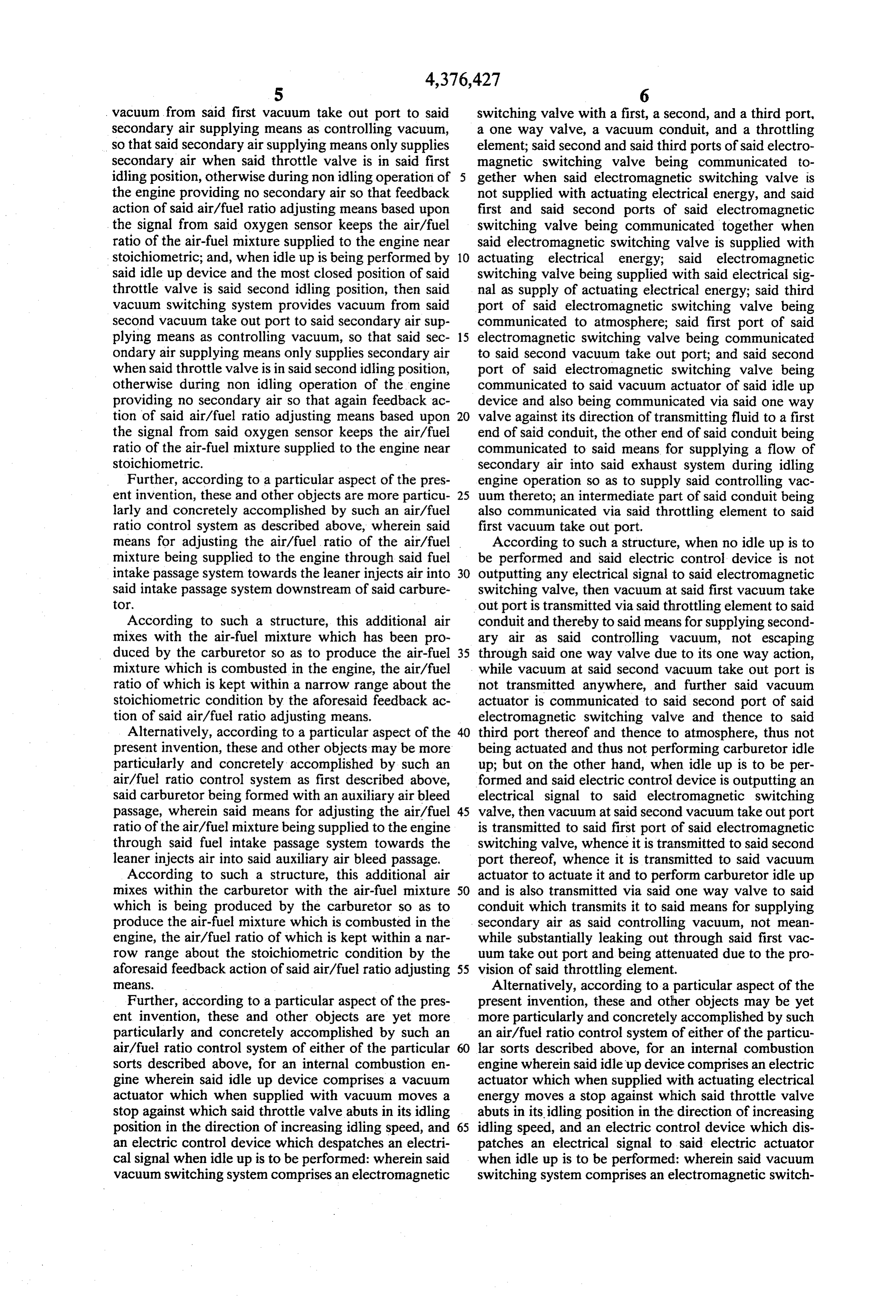
switching valve being communicated together when FIG. 3 is a part sectional part schematic construc said electromagnetic switching valve is not supplied tional view, similar to FIGS. 1 and 2, partially showing with actuating electrical energy, and said first and said an internal combustion engine and the intake and ex second ports of said electromagnetic switching valve haust systems thereof, and also showing in detail an being communicated together when said electromag air/fuel ratio control system which is a third preferred netic switching valve is supplied with actuating electri embodiment of the present invention as fitted to this cal energy; said electromagnetic switching valve being internal combustion engine; and supplied with said electrical signal as supply of actuat 10 FIG. 4 is a part sectional part schematic construc ing electrical energy; said third port of said electromag tional view, similar to FIGS. 1, 2, and 3, partially show netic switching valve being communicated to said first ing an internal combustion engine and the intake and vacuum take out port; said first port of said electromag exhaust systems thereof, and also showing in detail an netic switching valve being communicated to said sec air/fuel ratio control system which is a fourth preferred ond vacuum take out port; and said second port of said 15 embodiment of the present invention as fitted to this electromagnetic switching valve being communicated internal combustion engine.
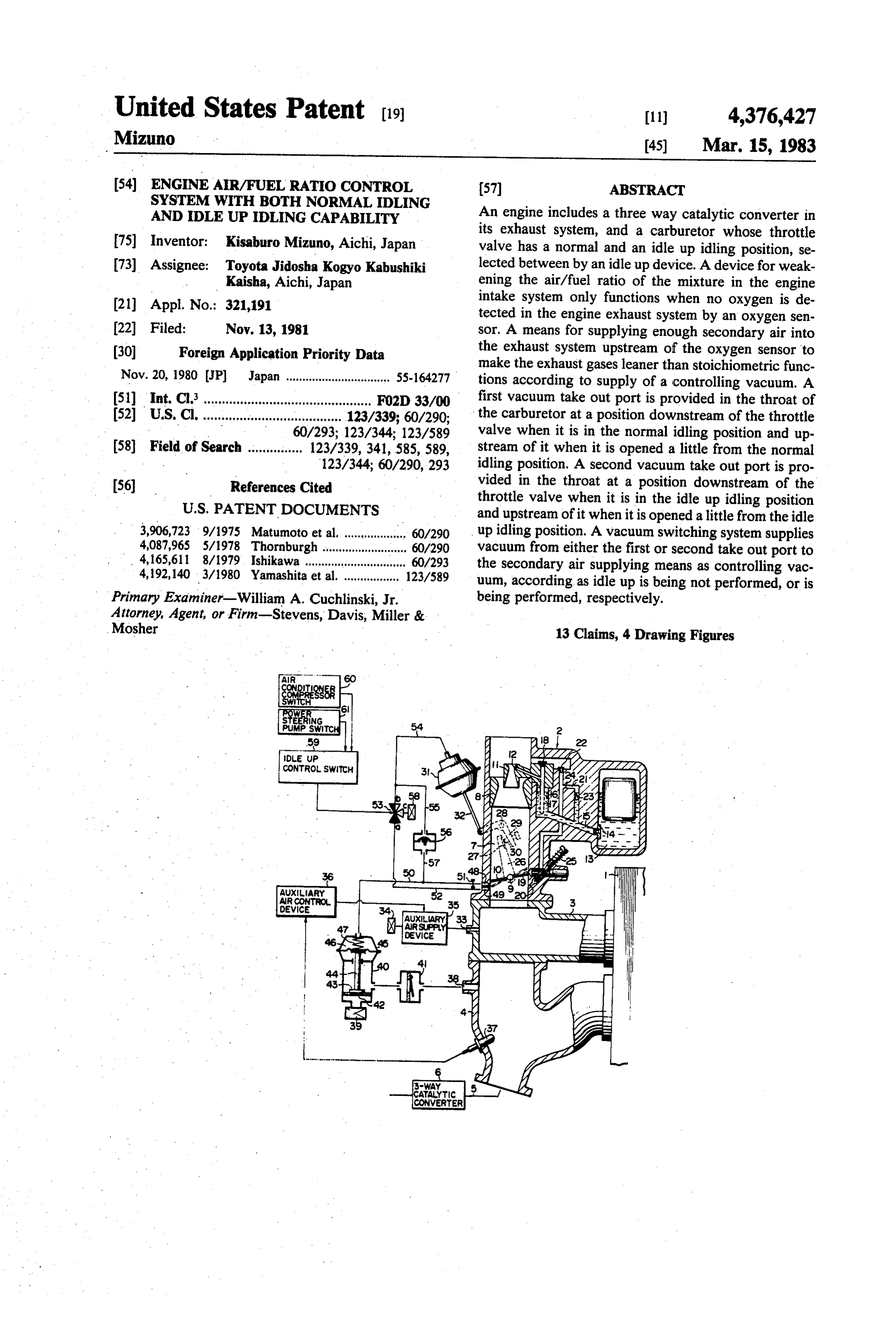
to said means for supplying a flow of secondary air into DESCRIPTION OF THE PREFERRED said exhaust system during idling engine operation so as EMBODIMENTS to supply said controlling vacuum thereto.
According to such a structure, when no idle up is to 20 The present invention will now be described with be performed and said electric control device is not reference to several preferred embodiments thereof, outputting any electrical signal to said electromagnetic and with reference to the appended drawings. switching valve and to said electric actuator, then vac Construction of the First Preferred Embodiment uum at said first vacuum take out port is transmitted to 25 FIG. 1 is a part sectional part schematic view, show said third port of said electromagnetic switching valve, ing an internal combustion engine 1 which is equipped whence it is transmitted to said second port thereof and with a first preferred embodiment of the air/fuel ratio therefrom to said means for supplying secondary air as said controlling vacuum, while vacuum at said second control system according to the present invention, and vacuum take out port is not transmitted anywhere, and 30 also showing various other control mechanisms associ ated therewith. The reference numeral 2 denotes a car further said electrical actuator is not being actuated and buretor which supplies fuel/air mixture to said internal thus not performing carburetor idle up; but on the other combustion engine 1 through an intake manifold 3. The hand, when idle up is to be performed and said electric fuel/air mixture control device is outputting an electrical signal to said bers, not shown,isofcombusted the in the combustion cham internal combustion engine 1, electromagnetic switching valve and to said electric 35 and the exhaust gases resulting from this combustion are actuator, then vacuum at said second vacuum take out exhausted through an exhaust manifold 4 into an ex port is transmitted to said first port of said electromag haust tube 5, at an intermediate part of which there is netic switching valve, whence it is transmitted to said fitted a three-way catalytic converter 6 of a perse well second port thereof and therefrom to said means for known sort; the exhaust tube 5 and the three-way cata supplying secondary air as said controlling vacuum, 40 lytic converter 6 are only shown schematically in FIG. while vacuum at said first vacuum take out port is not 1, because the details of their construction are not rele transmitted anywhere, and further said electrical actua Vant.
tor is actuated and thus is performing carburetor idle An air passage or throat 7 is formed through the body up. of the carburetor 2, and a large venturi 8 is fitted at an BRIEF DESCRIPTION OF THE DRAWINGS 45 upstream position in this throat 7. Downstream of the large venturi 8 within the carburetor throat 7 there is
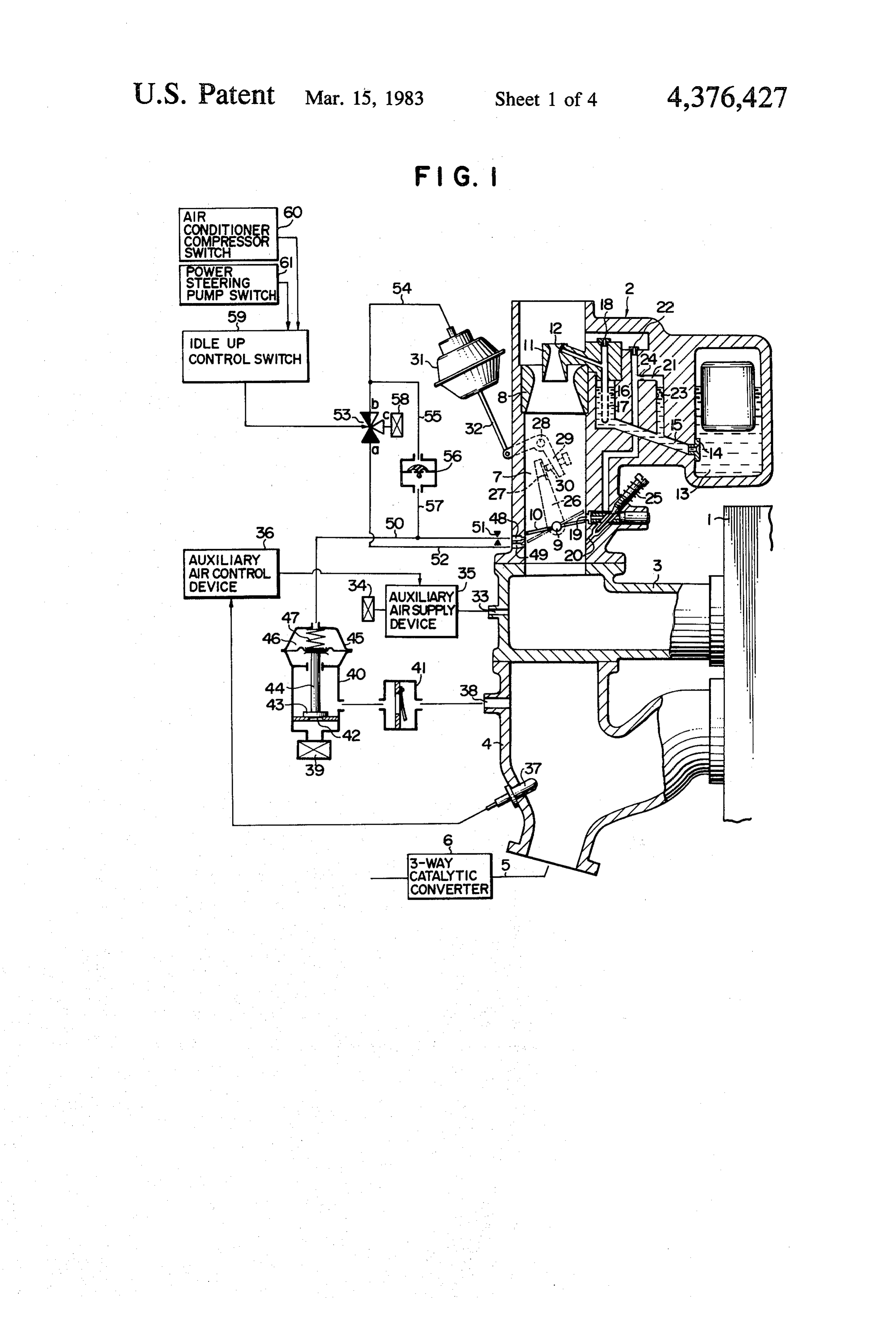
The present invention will now be shown and de fitted a butterfly type throttle valve 10, which is fixed to scribed with reference to several preferred embodi a throttle shaft 9 which is rotatably mounted in the ments thereof, and with reference to the illustrative walls of the throat 7, and which can rotate between a drawings. It should be clearly understood, however, 50 position as seen in solid lines in the figure in which it that the description of the embodiments, and the draw almost completely interrupts flow of gas through the ings, are all of them given purely for the purposes of throat 7, and a position in which it is quite wide open. explanation and exemplification only, and are none of Within the large venturi 8 there is fitted a small venturi them intended to be limitative of the scope of the pres 11, and within the small venturi 11 a main fuel nozzle 12 ent invention in any way, since the scope of the present 55 opens.
invention is to be defined solely by the legitimate and The carburetor 2 is provided with a float chamber 13, proper scope of the appended claims. In the drawings: and liquid fuel such as gasoline is kept at a predeter FIG. 1 is a part sectional part schematic construc mined constant level within this float chamber by a float tional view, partially showing an internal combustion and valve mechanism, not particularly shown or de engine and the intake and exhaust systems thereof, and 60 scribed here. Via a main fuel jet 14, this fuel flows from also showing in detail an air/fuel ratio control system the float chamber 13 into a main fuel passage 15, which which is a first preferred embodiment of the present leads it to a well 16. In the well 16 there is provided an invention as fitted to this internal combustion engine; air bleed tube 17 which is pierced with a plurality of FIG. 2 is a part sectional part schematic construc small holes for admitting bleed air into the liquid fuel tional view, similar to FIG. 1, partially showing an 65 within the well 16 from the atmosphere, via a main air internal combustion engine and the intake and exhaust bleed jet 18, in a per se conventional manner. systems thereof, and also showing in detail an air/fuel The body of the carburetor 2 is further provided with ratio control system which is a second preferred em a slow port 19 and an idle port 20, which are communi
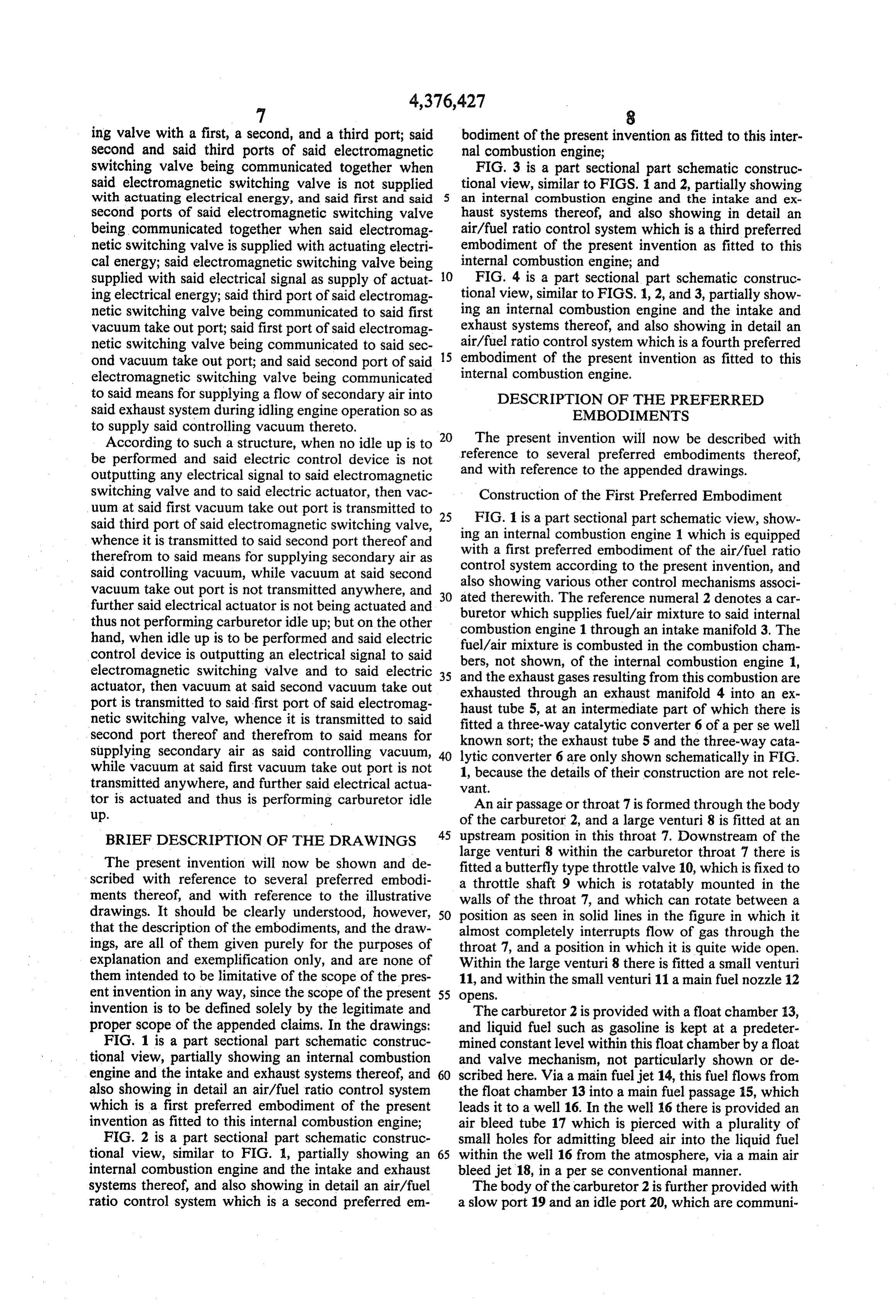
Page 10
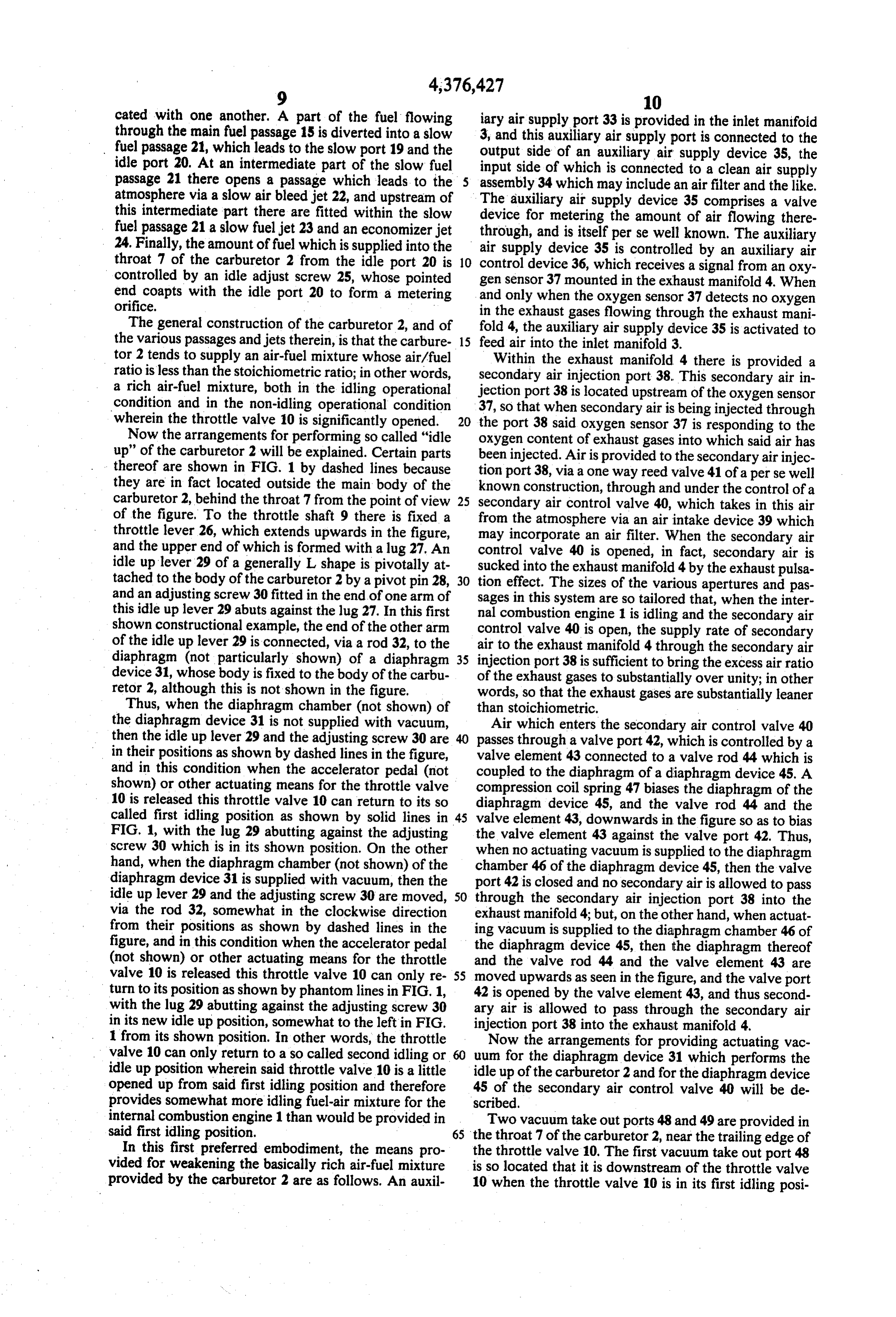
cated with one another. A part of the fuel flowing iary air supply port 33 is provided in the inlet manifold through the main fuel passage 15 is diverted into a slow 3, and this auxiliary air supply port is connected to the fuel passage 21, which leads to the slow port 19 and the output side of an auxiliary air supply device 35, the idle port 20. At an intermediate part of the slow fuel input side of which is connected to a clean air supply passage 21 there opens a passage which leads to the assembly 34 which may include an air filter and the like. atmosphere via a slow air bleed jet 22, and upstream of The auxiliary air supply device 35 comprises a valve this intermediate part there are fitted within the slow device for metering the amount of air flowing there fuel passage 21 a slow fuel jet 23 and an economizer jet through, and is itself per se well known. The auxiliary 24. Finally, the amount of fuel which is supplied into the air supply device 35 is controlled by an auxiliary air throat 7 of the carburetor 2 from the idle port 20 is 10 control device 36, which receives a signal from an oxy controlled by an idle adjust screw 25, whose pointed gen sensor 37 mounted in the exhaust manifold 4. When end coapts with the idle port 20 to form a metering and only when the oxygen sensor 37 detects no oxygen orifice. in the exhaust gases flowing through the exhaust mani The general construction of the carburetor 2, and of fold 4, the auxiliary air supply device 35 is activated to the various passages and jets therein, is that the carbure 15 feed air into the inlet manifold 3. tor 2 tends to supply an air-fuel mixture whose air/fuel Within the exhaust manifold 4 there is provided a ratio is less than the stoichiometric ratio; in other words, secondary air injection port 38. This secondary air in a rich air-fuel mixture, both in the idling operational jection port 38 is located upstream of the oxygen sensor condition and in the non-idling operational condition 37, so that when secondary air is being injected through wherein the throttle valve 10 is significantly opened. 20 the port 38 said oxygen sensor 37 is responding to the Now the arrangements for performing so called "idle oxygen content of exhaust gases into which said air has up' of the carburetor 2 will be explained. Certain parts been injected. Air is provided to the secondary air injec thereof are shown in FIG. 1 by dashed lines because tion port 38, via a one way reed valve 41 of a perse well they are in fact located outside the main body of the known construction, through and under the control of a carburetor 2, behind the throat 7 from the point of view 25 secondary air control valve 40, which takes in this air of the figure. To the throttle shaft 9 there is fixed a from the atmosphere via an air intake device 39 which throttle lever 26, which extends upwards in the figure, may incorporate an air filter. When the secondary air and the upper end of which is formed with a lug 27. An control valve 40 is opened, in fact, secondary air is idle up lever 29 of a generally L shape is pivotally at sucked into the exhaust manifold 4 by the exhaust pulsa tached to the body of the carburetor 2 by a pivot pin 28, 30 tion effect. The sizes of the various apertures and pas and an adjusting screw 30 fitted in the end of one arm of sages in this system are so tailored that, when the inter this idle up lever 29 abuts against the lug 27. In this first nal combustion engine 1 is idling and the secondary air shown constructional example, the end of the other arm control valve 40 is open, the supply rate of secondary of the idle up lever 29 is connected, via a rod 32, to the air to the exhaust manifold 4 through the secondary air diaphragm (not particularly shown) of a diaphragm 35 injection port 38 is sufficient to bring the excess air ratio device 31, whose body is fixed to the body of the carbu of the exhaust gases to substantially over unity; in other retor 2, although this is not shown in the figure. words, so that the exhaust gases are substantially leaner Thus, when the diaphragm chamber (not shown) of than stoichiometric.
the diaphragm device 31 is not supplied with vacuum, Air which enters the secondary air control valve 40 then the idle up lever 29 and the adjusting screw 30 are 40 passes through a valve port 42, which is controlled by a in their positions as shown by dashed lines in the figure, valve element 43 connected to a valve rod 44 which is and in this condition when the accelerator pedal (not coupled to the diaphragm of a diaphragm device 45. A shown) or other actuating means for the throttle valve compression coil spring 47 biases the diaphragm of the 10 is released this throttle valve 10 can return to its so diaphragm device 45, and the valve rod 44 and the called first idling position as shown by solid lines in 45 valve element 43, downwards in the figure so as to bias FIG. 1, with the lug 29 abutting against the adjusting the valve element 43 against the valve port 42. Thus, screw 30 which is in its shown position. On the other when no actuating vacuum is supplied to the diaphragm hand, when the diaphragm chamber (not shown) of the chamber 46 of the diaphragm device 45, then the valve diaphragm device 31 is supplied with vacuum, then the port 42 is closed and no secondary air is allowed to pass idle up lever 29 and the adjusting screw 30 are moved, 50 through the secondary air injection port 38 into the via the rod 32, somewhat in the clockwise direction exhaust manifold 4; but, on the other hand, when actuat from their positions as shown by dashed lines in the ing vacuum is supplied to the diaphragm chamber 46 of figure, and in this condition when the accelerator pedal the diaphragm device 45, then the diaphragm thereof (not shown) or other actuating means for the throttle and the valve rod 44 and the valve element 43 are valve 10 is released this throttle valve 10 can only re 55 moved upwards as seen in the figure, and the valve port turn to its position as shown by phantom lines in FIG. 1, 42 is opened by the valve element 43, and thus second with the lug 29 abutting against the adjusting screw 30 ary air is allowed to pass through the secondary air in its new idle up position, somewhat to the left in FIG. injection port 38 into the exhaust manifold 4. 1 from its shown position. In other words, the throttle Now the arrangements for providing actuating vac valve 10 can only return to a so called second idling or uum for the diaphragm device 31 which performs the idle up position wherein said throttle valve 10 is a little idle up of the carburetor 2 and for the diaphragm device opened up from said first idling position and therefore 45 of the secondary air control valve 40 will be de provides somewhat more idling fuel-air mixture for the scribed.
internal combustion engine 1 than would be provided in Two vacuum take out ports 48 and 49 are provided in said first idling position. 65 the throat 7 of the carburetor 2, near the trailing edge of In this first preferred embodiment, the means pro the throttle valve 10. The first vacuum take out port 48 vided for weakening the basically rich air-fuel mixture is so located that it is downstream of the throttle valve provided by the carburetor 2 are as follows. An auxil 10 when the throttle valve 10 is in its first idling posi
Page 11
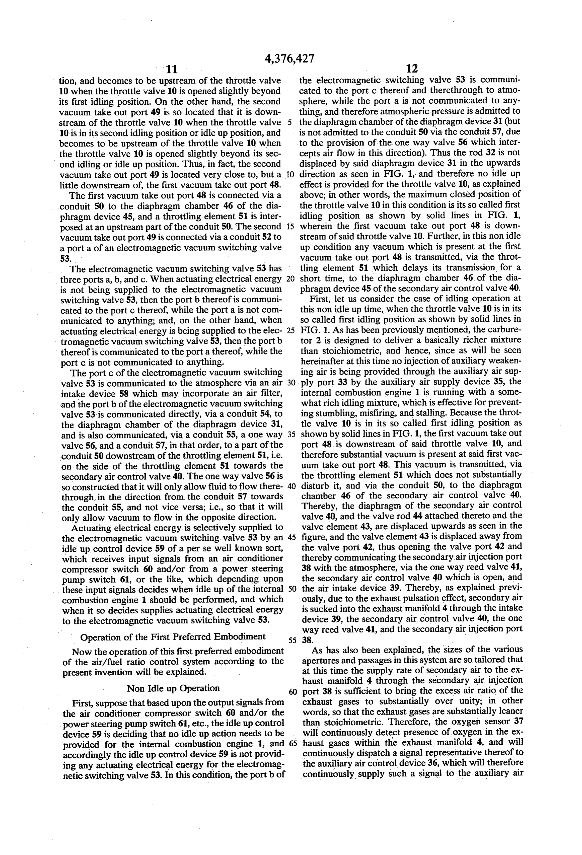
tion, and becomes to be upstream of the throttle valve the electromagnetic switching valve 53 is communi 10 when the throttle valve 10 is opened slightly beyond cated to the port c thereof and therethrough to atmo its first idling position. On the other hand, the second sphere, while the port a is not communicated to any vacuum take out port 49 is so located that it is down thing, and therefore atmospheric pressure is admitted to stream of the throttle valve 10 when the throttle valve the diaphragm chamber of the diaphragm device 31 (but 10 is in its second idling position or idle up position, and is not admitted to the conduit 50 via the conduit 57, due becomes to be upstream of the throttle valve 10 when to the provision of the one way valve 56 which inter the throttle valve 10 is opened slightly beyond its sec cepts air flow in this direction). Thus the rod 32 is not ond idling or idle up position. Thus, in fact, the second displaced by said diaphragm device 31 in the upwards vacuum take out port 49 is located very close to, but a O direction as seen in FIG. 1, and therefore no idle up little downstream of, the first vacuum take out port 48. effect is provided for the throttle valve 10, as explained The first vacuum take out port 48 is connected via a above; in other words, the maximum closed position of conduit 50 to the diaphragm chamber 46 of the dia the throttle valve 10 in this condition is its so called first phragm device 45, and a throttling element 51 is inter idling position as shown by solid lines in FIG. 1, posed at an upstream part of the conduit 50. The second 15 wherein the first vacuum take out port 48 is down vacuum take out port 49 is connected via a conduit 52 to stream of said throttle valve 10. Further, in this non idle a porta of an electromagnetic vacuum switching valve up condition any vacuum which is present at the first 53. vacuum take out port 48 is transmitted, via the throt The electromagnetic vacuum switching valve 53 has tling element 51 which delays its transmission for a three ports a, b, and c. When actuating electrical energy 20 short time, to the diaphragm chamber 46 of the dia is not being supplied to the electromagnetic vacuum phragm device 45 of the secondary air control valve 40. switching valve 53, then the port b thereof is communi First, let us consider the case of idling operation at cated to the port c thereof, while the port a is not com this non idle up time, when the throttle valve 10 is in its municated to anything; and, on the other hand, when so called first idling position as shown by solid lines in actuating electrical energy is being supplied to the elec 25 FIG. 1. As has been previously mentioned, the carbure tromagnetic vacuum switching valve 53, then the port b tor 2 is designed to deliver a basically richer mixture thereof is communicated to the port a thereof, while the than stoichiometric, and hence, since as will be seen port c is not communicated to anything. hereinafter at this time no injection of auxiliary weaken The port c of the electromagnetic vacuum switching ing air is being provided through the auxiliary air sup valve 53 is communicated to the atmosphere via an air 30 ply port 33 by the auxiliary air supply device 35, the intake device 58 which may incorporate an air filter, internal combustion engine 1 is running with a some and the port b of the electromagnetic vacuum switching what rich idling mixture, which is effective for prevent valve 53 is communicated directly, via a conduit 54, to ing stumbling, misfiring, and stalling. Because the throt the diaphragm chamber of the diaphragm device 31, tle valve 10 is in its so called first idling position as and is also communicated, via a conduit 55, a one way 35 shown by solid lines in FIG. 1, the first vacuum take out valve 56, and a conduit 57, in that order, to a part of the port 48 is downstream of said throttle valve 10, and conduit 50 downstream of the throttling element 51, i.e. therefore substantial vacuum is present at said first vac on the side of the throttling element 51 towards the uum take out port 48. This vacuum is transmitted, via secondary air control valve 40. The one way valve 56 is the throttling element 51 which does not substantially so constructed that it will only allow fluid to flow there disturb it, and via the conduit 50, to the diaphragm through, in the direction from the conduit 57 towards chamber 46 of the secondary air control valve 40. the conduit 55, and not vice versa; i.e., so that it will Thereby, the diaphragm of the secondary air control only allow vacuum to flow in the opposite direction. valve 40, and the valve rod 44 attached thereto and the Actuating electrical energy is selectively supplied to valve element 43, are displaced upwards as seen in the the electromagnetic vacuum switching valve 53 by an 45 figure, and the valve element 43 is displaced away from the valve port 42, thus opening the valve port 42 and idle up control device 59 of a perse well known sort, thereby which receives input signals from an air conditioner communicating the secondary air injection port compressor switch 60 and/or from a power steering 38 with the atmosphere, via the one way reed valve 41, pump switch 61, or the like, which depending upon the secondary air control valve 40 which is open, and these input signals decides when idle up of the internal 50 the air intake device 39. Thereby, as explained previ combustion engine 1 should be performed, and which ously, due to the exhaust pulsation effect, secondary air when it so decides supplies actuating electrical energy is sucked into the exhaust manifold 4 through the intake to the electromagnetic vacuum switching valve 53. device 39, the secondary air control valve 40, the one way reed valve 41, and the secondary air injection port
Operation of the First Preferred Embodiment 55 38.
Now the operation of this first preferred embodiment As has also been explained, the sizes of the various of the air/fuel ratio control system according to the apertures and passages in this system are so tailored that present invention will be explained. at this time the supply rate of secondary air to the ex haust manifold 4 through the secondary air injection
Non Idle up Operation port 38 is sufficient to bring the excess air ratio of the First, suppose that based upon the output signals from exhaust gases to substantially over unity; in other the air conditioner compressor switch 60 and/or the words, so that the exhaust gases are substantially leaner power steering pump switch 61, etc., the idle up control than stoichiometric. Therefore, the oxygen sensor 37 device 59 is deciding that no idle up action needs to be will continuously detect presence of oxygen in the ex provided for the internal combustion engine 1, and 65 haust gases within the exhaust manifold 4, and will accordingly the idle up control device 59 is not provid continuously dispatch a signal representative thereof to ing any actuating electrical energy for the electromag the auxiliary air control device 36, which will therefore netic switching valve 53. In this condition, the port b of continuously supply such a signal to the auxiliary air
Page 12
supply device 35 as to cause it not to feed any auxiliary air-fuel mixture provided to the internal combustion air into the inlet manifold 3 through the auxiliary air engine 1 is brought to be substantially the stoichiomet supply port 33, as mentioned above. Further, during ric value, by addition of the proper amount of auxiliary this operational condition, the excess air ratio of the air thereto through the auxiliary air supply port 33. exhaust gases within the exhaust manifold 4 and being When this substantially stoichiometric air/fuel ratio for fed into the three way catalytic converter 6 through the the intake gases of the internal combustion engine 1 has exhaust tube 5 is substantially over unity-in other been attained, then the excess air ratio of the exhaust words, the exhaust gases have surplus oxygen in them gases in the exhaust manifold 4 and passed through the -and therefore the three way catalytic converter 6 is three way catalytic converter 6 will be approximately being operated substantially only as an oxidizing cata 10 1-i.e., these exhaust gases will be near the stoichiomet lytic converter, eliminating HC and CO and other prod ric condition-and therefore the three way catalytic ucts of incomplete combustion in the exhaust gases of converter 6 will function properly and effectively in its the internal combustion engine 1 by an oxidizing reac three way catalytic mode of removing not only HC, tion, but not substantially operating in the reduction CO, and other products of incomplete combustion from mode to eliminate NOx from the exhaust gases; how 15 the exhaust gases by an oxidising reaction, but also of ever, since in this rich idling operational condition of purifying the exhaust gases of NOx by a reducing reac the internal combustion engine 1 the production of NOx tion.
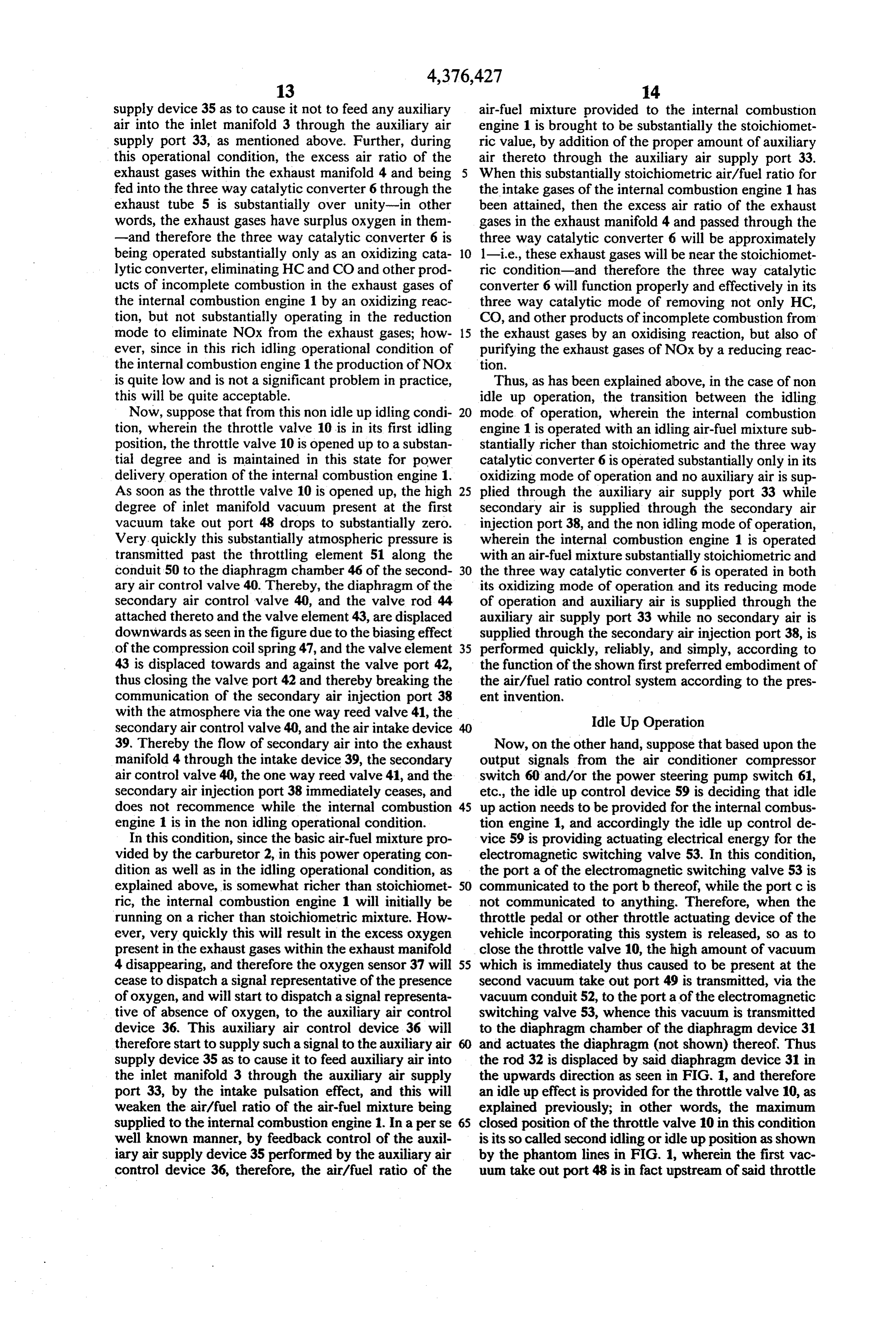
is quite low and is not a significant problem in practice, Thus, as has been explained above, in the case of non this will be quite acceptable. idle up operation, the transition between the idling Now, suppose that from this non idle up idling condi 20 mode of operation, wherein the internal combustion tion, wherein the throttle valve 10 is in its first idling engine 1 is operated with an idling air-fuel mixture sub position, the throttle valve 10 is opened up to a substan stantially richer than stoichiometric and the three way tial degree and is maintained in this state for power catalytic converter 6 is operated substantially only in its delivery operation of the internal combustion engine 1. oxidizing mode of operation and no auxiliary air is sup As soon as the throttle valve 10 is opened up, the high 25 plied through the auxiliary air supply port 33 while degree of inlet manifold vacuum present at the first secondary air is supplied through the secondary air vacuum take out port 48 drops to substantially zero. injection port 38, and the non idling mode of operation, Very. quickly this substantially atmospheric pressure is wherein the internal combustion engine 1 is operated transmitted past the throttling element 51 along the with an air-fuel mixture substantially stoichiometric and conduit 50 to the diaphragm chamber 46 of the second 30 the three way catalytic converter 6 is operated in both ary air control valve 40. Thereby, the diaphragm of the its oxidizing mode of operation and its reducing mode secondary air control valve 40, and the valve rod 44 of operation and auxiliary air is supplied through the attached thereto and the valve element 43, are displaced auxiliary air supply port 33 while no secondary air is downwards as seen in the figure due to the biasing effect supplied through the secondary air injection port 38, is of the compression coil spring 47, and the valve element 35 performed quickly, reliably, and simply, according to 43 is displaced towards and against the valve port 42, the function of the shown first preferred embodiment of thus closing the valve port 42 and thereby breaking the the air/fuel ratio control system according to the pres communication of the secondary air injection port 38 ent invention, with the atmosphere via the one way reed valve 41, the Idle Up Operation secondary air control valve 40, and the air intake device 39. Thereby the flow of secondary air into the exhaust Now, on the other hand, suppose that based upon the manifold 4 through the intake device 39, the secondary output signals from the air conditioner compressor air control valve 40, the one way reed valve 41, and the switch 60 and/or the power steering pump switch 61, secondary air injection port 38 immediately ceases, and etc., the idle up control device 59 is deciding that idle does not recommence while the internal combustion 45 up action needs to be provided for the internal combus engine 1 is in the non idling operational condition. tion engine 1, and accordingly the idle up control de In this condition, since the basic air-fuel mixture pro vice 59 is providing actuating electrical energy for the vided by the carburetor 2, in this power operating con electromagnetic switching valve 53. In this condition, dition as well as in the idling operational condition, as the porta of the electromagnetic switching valve 53 is explained above, is somewhat richer than stoichiomet 50 communicated to the port b thereof, while the port c is ric, the internal combustion engine 1 will initially be not communicated to anything. Therefore, when the running on a richer than stoichiometric mixture. How throttle pedal or other throttle actuating device of the ever, very quickly this will result in the excess oxygen vehicle incorporating this system is released, so as to present in the exhaust gases within the exhaust manifold close the throttle valve 10, the high amount of vacuum 4 disappearing, and therefore the oxygen sensor 37 will 55 which is immediately thus caused to be present at the cease to dispatch a signal representative of the presence second vacuum take out port 49 is transmitted, via the of oxygen, and will start to dispatch a signal representa vacuum conduit 52, to the porta of the electromagnetic tive of absence of oxygen, to the auxiliary air control switching valve 53, whence this vacuum is transmitted device 36. This auxiliary air control device 36 will to the diaphragm chamber of the diaphragm device 31 therefore start to supply such a signal to the auxiliary air and actuates the diaphragm (not shown) thereof. Thus supply device 35 as to cause it to feed auxiliary air into the rod 32 is displaced by said diaphragm device 31 in the inlet manifold 3 through the auxiliary air supply the upwards direction as seen in FIG. 1, and therefore port 33, by the intake pulsation effect, and this will an idle up effect is provided for the throttle valve 10, as weaken the air/fuel ratio of the air-fuel mixture being explained previously; in other words, the maximum supplied to the internal combustion engine 1. In a perse 65 closed position of the throttle valve 10 in this condition well known manner, by feedback control of the auxil is its so called second idling or idle upposition as shown iary air supply device 35 performed by the auxiliary air by the phantom lines in FIG. 1, wherein the first vac control device 36, therefore, the air/fuel ratio of the uum take out port 48 is in fact upstream of said throttle
Page 13
valve 10, but the second vacuum take out port 49 is just supply port 33, as mentioned above. Further, during downstream of said throttle valve 10, Further, in this this operational condition, the excess air ratio of the idle up condition any vacuum which is present at the exhaust gases within the exhaust manifold 4 and being second vacuum take out port 49 is transmitted, via the fed into the three way catalytic converter 6through the conduit 52, the electromagnetic switching valve 53, the exhaust tube 5 is substantially over unity-in other conduit 54, the conduit 55, the one way valve 56, the words, the exhaust gases have surplus oxygen in them conduit 57, and the conduit 50, to the diaphragm cham -and therefore the three way catalytic converter 6 is ber 46 of the diaphragm device 45 of the secondary air being operated substantially only as an oxidizing cata control valve 40. In this connection, by the way, sub lytic converter, eliminating HC and CO and other prod stantial escape of such vacuum through the upstream 10 ucts of incomplete combustion in the exhaust gases of part of the conduit 50 in the reverse direction through the internal combustion engine 1 by an oxidizing reac the first vacuum take out port 48 is prevented by the tion, but not substantially operating in the reduction provision of the throttling element 51. mode to eliminate NOx from the exhaust gases; how First, let us consider the case of idling operation at ever, since in this rich idle up idling operational condi this idle up time, when the throttle valve 10 is in its so 15 tion of the internal combustion engine 1 the production called second idling position as shown by the phantom of NOx is quite low and is not a significant problem in lines in FIG. 1. As has been previously mentioned, the practice, this will be quite acceptable. carburetor 2 is designed to deliver a basically richer Now, suppose that from this idle up idling condition, mixture than stoichiometric, and hence, since as will be wherein the throttle valve 10 is in its second or idle up seen hereinafter at this time no injection of auxiliary idling position, the throttle valve 10 is opened up to a weakening air is being provided through the auxiliary Substantial degree and is maintained in this state for air supply port 33 by the auxiliary air supply device 35, power delivery operation of the internal combustion the internal combustion engine 1 is running with a engine 1. As soon as the throttle valve 10 is opened up, somewhat rich idling mixture, which is effective for the high degree of inlet manifold vacuum present at the preventing stumbling, misfiring, and stalling. Because 25 second vacuum take out port 49 drops to substantially the throttle valve 10 is in its so called second idling Zero. Very quickly this substantially atmospheric pres position as shown by phantom lines in FIG. 1, the sec sure is transmitted via the conduit 52, the electromag ond vacuum take out port 49 is downstream of said netic switching valve 53 whose ports a and b are com throttle valve 10, and therefore substantial vacuum is municated to one another at this time, via the conduits present at said second vacuum take out port 49. This 30 54 and 55, via the one way valve 56, and via the con vacuum is transmitted, via the conduit 52, the electro duits 57 and 50, to the diaphragm chamber 46 of the magnetic switching valve 53 whose ports a and b are as secondary air control valve 40. Thereby, the diaphragm stated above communicated to one another at this time, of the secondary air control valve 40, and the valve rod via the conduits 54 and 55, via the one way valve 56, 44 attached thereto and the valve element 43, are dis and via the conduits 57 and 50, to the diaphragm cham 35 placed downwards as seen in the figure due to the bias ber 46 of the secondary air control valve 40 (not being ing effect of the compression coil spring 47, and the substantially attenuated by leakage past the throttling valve element 43 is displaced towards and against the element 51 to the first vacuum take out port 48, due to valve port 42, thus closing the valve port 42 and thereby the high flow resistance of said throttling element 51). breaking the communication of the secondary air injec Thereby, the diaphragm of the secondary air control 40 tion port 38 with the atmosphere via the one way reed valve 40, and the valve rod 44 attached thereto and the valve 41, the secondary air control valve 40, and the air valve element 43, are displaced upwards as seen in the intake device 39. Thereby the flow of secondary air into figure, and the valve element 43 is displaced away from the exhaust manifold 4 through the intake device 39, the the valve port 42, thus opening the valve port 42 and secondary air control valve 40, the one way reed valve thereby communicating the secondary air injection port 45 41, and the secondary air injection port 38 immediately 38 with the atmosphere, via the one way reed valve 41, ceases, and does not recommence while the internal the secondary air control valve 40 which is open, and combustion engine is in the non idling operational the air intake device 39. Thereby, as explained previ condition.
ously, due to the exhaust pulsation effect, secondary air In this condition, since the basic air-fuel mixture pro is sucked into the exhaust manifold 4 through the intake 50 vided by the carburetor 2, in this power operating con device 39, the secondary air control valve 40, the one dition as well as in the idle up idling operational condi way reed valve 41, and the secondary air injection port tion, as explained above, is somewhat richer than stoi 38. chiometric, the internal combustion engine 1 will ini As has also been previously stated, the sizes of the tially be running on a richer than stoichiometric mix various apertures and passages in this system are so 55 ture. However, very quickly this will result in the ex tailored that at this time the supply rate of secondary air cess oxygen present in the exhaust gases within the to the exhaust manifold 4 through the secondary air exhaust manifold 4 disappearing, and therefore the oxy injection port 38 is sufficient to bring the excess air ratio gen sensor 37 will cease to dispatch a signal representa of the exhaust gases to substantially over unity; in other tive of the presence of oxygen, and will start to dispatch words, so that the exhaust gases are substantially leaner 60 a signal representative of absence of oxygen, to the than stoichiometric. Therefore, the oxygen sensor 37 auxiliary air control device 36. This auxiliary air control will continuously detect presence of oxygen in the ex device 36 will therefore start to supply such a signal to haust gases within the exhaust manifold 4, and will the auxiliary air supply device 35 as to cause it to feed, continuously dispatch a signal representative thereof to by the intake pulsation effect, auxiliary air into the inlet the auxiliary air control device 36, which will therefore 65 manifold 3 through the auxiliary air supply port 33, and continuously supply such a signal to the auxiliary air this will weaken the air/fuel ratio of the air-fuel mixture supply device 35 as to cause it not to feed any auxiliary being supplied to the internal combustion engine 1. In a air into the inlet manifold 3 through the auxiliary air perse well known manner, by feedback control of the
Page 14
auxiliary air supply device 35 performed by the auxil parts of the first preferred embodiment shown in FIG. iary air control device 36, therefore, the air/fuel ratio of 1, and which have the same functions, are designated by the air-fuel mixture provided to the internal combustion engine 1 is brought to be substantially the stoichiomet the same reference numerals and symbols as in that figure.
ric value, by addition of the proper amount of auxiliary air thereto through the auxiliary air supply port 33. tionIn engine FIG. 2, there is again shown an internal combus 1, which is now equipped with a second
When this substantially stoichiometric air/fuel ratio for preferred embodiment of the air/fuel ratio control sys the intake gases of the internal combustion engine 1 has tem according to the present invention. The reference been attained, then the excess air ratio of the exhaust numeral 2 again denotes a carburetor which supplies gases in the exhaust manifold 4 and passed through the 10 fuel/air mixture to said internal combustion engine 1 three way catalytic converter 6 will be approximately through an intake manifold 3. The fuel/air mixture is 1-i.e., these exhaust gases will be near the stoichiomet combusted in the combustion chambers, not shown, of ric condition-and therefore the three way catalytic the internal combustion engine 1, and the exhaust gases converter 6 will function properly and effectively in its resulting from this combustion are again exhausted three way catalytic mode of removing not only HC, 15 through an exhaust manifold 4 into an exhaust tube 5, at CO, and other products of incomplete combustion from an intermediate part of which there is again fitted a the exhaust gases by an oxidising reaction, but also of three-way catalytic converter 6 of a perse well known purifying the exhaust gases of NOx by a reducing reac sort; the exhaust tube 5 and the three-way catalytic tion. converter 6 are again only shown schematically in FIG. Thus, as has been explained above, in the case of idle 20 2, because the details of their construction are not rele up operation, the transition between the idle up idling Vant.
mode of operation, wherein the internal combustion The details of the internal construction of the carbu engine 1 is operated with an idle up idling air-fuel mix retor 2 are exactly the same as those of the carburetor 2 ture substantially richer than stoichiometric and the shown with regard to the description of the first pre three way catalytic converter 6 is operated substantially 25 ferred embodiment of the air/fuel ratio control system only in its oxidizing mode of operation and no auxiliary according to the present invention, and hence explana air is supplied through the auxiliary air supply port 33 tion thereof is omitted here in order to avoid redun while secondary air is supplied through the secondary dancy of description. The general construction of the air injection port 38, and the non idling mode of opera carburetor 2, and of the various passages and jets tion, wherein the internal combustion engine 1 is oper 30 therein, again with regard to this second preferred em ated with an air-fuel mixture substantially stoichiomet bodiment, is that the carburetor 2 tends to supply an ric and the three way catalytic converter 6 is operated air-fuel mixture whose air/fuel ratio is less than the in both its oxidizing mode of operation and its reducing stoichiometric ratio; in other words, a rich air-fuel mix mode of operation and auxiliary air is supplied through ture, both in the idling operational condition and in the the auxiliary air supply port 33 while no secondary air is 35 non-idling operational condition wherein the throttle supplied through the secondary air injection port 38, is valve 10 is significantly opened.
performed quickly, reliably, and simply, according to Now the arrangements for performing so called "idle the function of the shown first preferred embodiment of up' of the carburetor 2 will be explained, which differ the air/fuel ratio control system according to the pres in this case. As before, certain parts thereof are shown ent invention. 40 in FIG. 2 by dashed lines because they are in fact lo In summary, as will be clear from the above, in both cated outside the main body of the carburetor 2, behind the non idle up mode of operation of the shown first the throat 7 from the point of view of the figure. To the preferred embodiment of the air/fuel ratio control sys throttle shaft 9 there is fixed a throttle lever 26, which tem according to the present invention, and the idle up extends upwards in the figure, and the upper end of mode of operation thereof: when the throttle valve 10 is 45 which is formed with a lug 27. An idle up lever 29 of a in its idling position (respectively either the non idle up generally L shape is pivotally attached to the body of idling position or the idle up idling position) then the the carburetor 2 by a pivot pin 28, and an adjusting internal combustion engine 1 is operated with an air-fuel screw 30 fitted in the end of one arm of this idle up lever mixture with an air/fuel ratio which is substantially 29 abuts against the lug 27. In this second particular richer than the stoichiometric one, which is effective 50 construction, however, in contradistinction to the first for preventing stumbling, misfiring, and stalling of said construction shown in FIG. 1, the end of the other arm internal combustion engine 1 during idling; while, on of the idle up lever 29 is connected to the plunger 63 of the other hand, when the throttle valve 10 is moved a solenoid device 62, whose body is fixed to the body of away from its idling position (whichever of the above the carburetor 2, although this is not shown in the fig non idle up or idle up idling positions said idling posi 55 e.
tion may respectively currently be) by even a small Thus, when the coil (not shown) of the solenoid de amount, then the internal combustion engine 1 is oper vice 62 is not supplied with actuating electrical energy, ated with an air-fuel mixture with an air/fuel ratio then the idle up lever 29 and the adjusting screw 30 are which is substantially stoichiometric, which is effective in their positions as shown by dashed lines in the figure, for promoting proper operation of the three way cata and in this condition when the accelerator pedal (not lytic converter 6 in its three way operational mode. shown) or other actuating means for the throttle valve Construction of the Second Preferred Embodiment 10 is released this throttle valve 10 can return to its so called first idling position as shown by solid lines in
In FIG. 2, there is shown a part sectional view of a FIG. 2, with the lug 29 abutting against the adjusting second preferred embodiment of the air/fuel ratio con screw 30 which is in its shown position. On the other trol system according to the present invention, in a hand, when the coil (not shown) of the solenoid device fashion similar to FIG. 1. In FIG. 2, parts of the second 62 is supplied with actuating electrical energy, then the preferred embodiment shown, which correspond to idle up lever 29 and the adjusting screw 30 are moved,
Page 15
via the rod 32, somewhat in the clockwise direction throttle valve 10 is in its second idling position or idle from their positions as shown by dashed lines in the up position, and becomes to be upstream of the throttle figure, and in this condition when the accelerator pedal valve 10 when the throttle valve 10 is opened slightly (not shown) or other actuating means for the throttle beyond its second idling or idle up position. Thus, in valve 10 is released this throttle valve 10 can only re fact, the second vacuum take out port 49 is located very turn to its position as shown by phantom lines in FIG. 2, close to, but a little downstream of, the first vacuum with the lug 29 abutting against the adjusting screw 30 take out port 48, in a fashion identical to that of the first in its new idle up position, somewhat to the left in FIG. preferred embodiment.
2 from its shown position. In other words, the throttle The first vacuum take out port 48 is connected via a valve 10 can only return to a so called second idling or 10 conduit 64 to a port c of an electromagnetic vacuum idle up position wherein said throttle valve 10 is a little switching valve 65. The second vacuum take out port opened up from said first idling position and therefore 49 is connected via a conduit 66 to another porta of said provides somewhat more idling fuel-air mixture for the electromagnetic vacuum switching valve 65. And the internal combustion engine 1 than would be provided in port b of the electromagnetic vacuum switching valve said first idling position. 15 65 is communicated directly, via a conduit 67, to the In this second preferred embodiment, the construc diaphragm chamber 46 of the diaphragm device 45 of tion of the system for selectively providing auxiliary air the secondary air control valve 40. .. . into the inlet manifold 3 in order to weaken the some The communications between the ports a, b, and c of what richer than stoichiometric air-fuel mixture which the electromagnetic vacuum switching valve 65 are as is being provided by the carburetor 2, comprising the 20 follows. When actuating electrical energy is not being auxiliary air supply port 33, the auxiliary air supply supplied to the electromagnetic vacuum switching device 35, the clean air supply assembly 34, the auxiliary valve 65, then the port b thereof is communicated to the air control device 36, and the oxygen sensor 37, is ex port c thereof, while the port a is not communicated to actly the same as in the first preferred embodiment of anything; and, on the other hand, when actuating elec the air/fuel ratio control device according to the pres 25 trical energy is being supplied to the electromagnetic ent invention shown in FIG. 1, and hence explanation vacuum switching valve 65, then the port b thereof is thereof is omitted here in order to avoid redundancy of communicated to the port a thereof, while the port c is description. not communicated to anything. Within the exhaust manifold 4 there is again provided Actuating electrical energy is selectively supplied a secondary air injection port 38, upstream of the oxy 30 both to the electromagnetic vacuum switching valve 65 gen sensor 37, which in exactly the same way as in the and to the solenoid device 62, in parallel, by an idle up first preferred embodiment shown in FIG. 1 is selec control device 59 of a sort identical to the one shown tively provided with air via a one way reed valve 41 of with regard to the first preferred embodiment of the a per se well known construction, through and under present invention, which receives input signals from an the control of a secondary air control valve 40, which 35 air conditioner compressor switch 60 and/or from a takes in this air from the atmosphere via an air intake power steering pump switch 61, or the like, which de device 39 which may incorporate an air filter. When the pending upon these input signals decides when idle up secondary air control valve 40 is opened, again, second of the internal combustion engine 1 should be per ary air is sucked into the exhaust manifold 4 by the formed, and which when it so decides supplies actuating exhaust pulsation effect. Again, the sizes of the various electrical energy both to the electromagnetic vacuum apertures and passages in this system are so tailored switching valve 65 and to the solenoid device 62. that, when the internal combustion engine 1 is idling Thus it will be seen that this second preferred em and the secondary air control valve 40 is open, the bodiment of the air/fuel ratio control system according supply rate of secondary air to the exhaust manifold 4 to the present invention is in fact simpler in construction through the secondary air injection port 38 is sufficient 45 than is the first preferred embodiment, and is also sim to bring the excess air ratio of the exhaust gases to sub pler in conception, because of the use of an electrical i. stantially over unity; in other words, so that the exhaust actuator (the solenoid device 62) for performing idle up gases are substantially leaner than stoichiometric. of the carburetor 2.
The details of the internal construction of the second ary air control valve 40 are exactly the same as those of 50 Operation of the Second Idle Up
Preferred Embodiment Non
Operation the secondary air control valve 40 shown with regard to the description of the first preferred embodiment of the First, suppose that based upon the output signals from air/fuel ratio control system according to the present the air conditioner compressor switch 60 and/or the invention, and hence explanation thereof is omitted here power steering pump switch 61, etc., the idle up control in order to avoid redundancy of description. Now the 55 device 59 is deciding that no idle up action needs to be arrangements for providing actuating vacuum for the provided for the internal combustion engine 1, and diaphragm device 45 of the secondary air control valve accordingly the idle up control device 59 is not provid 40 will be described. ing any actuating electrical energy for the solenoid As before, two vacuum take out ports 48 and 49 are device 62 or for the electromagnetic switching valve 65. provided in the throat 7 of the carburetor 2, near the In this condition, the port b of the electromagnetic trailing edge of the throttle valve 10. The first vacuum switching valve 65 is communicated to the port c take out port 48 is so located that it is downstream of the thereof, while the port a is not communicated to any throttle valve 10 when the throttle valve 10 is in its first thing, and therefore in this non idle up condition any idling position, and becomes to be upstream of the vacuum which is present at the first vacuum take out throttle valve 10 when the throttle valve 10 is opened 65 port 48 is transmitted, via the electromagnetic switch slightly beyond its first idling position. On the other ing valve 65, to the diaphragm chamber 46 of the dia hand, the second vacuum take out port 49 is so located phragm device 45 of the secondary air control valve 40. that it is downstream of the throttle valve 10 when the Further, no actuating electrical energy is provided to
Page 16
the solenoid device 62 by the idle up control device 59, incomplete combustion in the exhaust gases of the inter and thus the rod 32 is not displaced by said solenoid nal combustion engine 1 by an oxidizing reaction, but device 62 in the upwards direction as seen in FIG. 2, not substantially operating in the reduction mode to and therefore no idle up effect is provided for the throt eliminate NOx from the exhaust gases; however, since tle valve 10, as explained above; in other words, the in this rich idling operational condition of the internal maximum closed position of the throttle valve 10 in this combustion engine 1 the production of NOx is quite low condition is its so called first idling position as shown by and is not a significant problem in practice, this will be solid lines in FIG. 2, wherein the first vacuum take out quite acceptable.
port 48 is downstream of said throttle valve 10. Now, suppose that from this non idle up idling condi First, let us consider the case of idling operation at 10 tion, wherein the throttle valve 10 is in its first idling this non idle up time, when the throttle valve 10 is in its position, the throttle valve 10 is opened up to a substan so called first idling position as shown by solid lines in tial degree and is maintained in this state for power FIG. 2. As in the case of the carburetor to which the delivery operation of the internal combustion engine 1. first preferred embodiment was applied, the carburetor As soon as the throttle valve 10 is opened up, the high 2 of this second preferred embodiment is designed to 15 degree of inlet manifold vacuum present at the first deliver a basically richer mixture than stoichiometric, vacuum take out port 48 drops to substantially zero. and hence, since as will be seen hereinafter at this time Very quickly this substantially atmospheric pressure is no injection of auxiliary weakening air is being pro transmitted along the conduit 64, past the electromag vided through the auxiliary air supply port 33 by the netic switching valve 65, and along the conduit 67 to auxiliary air supply device 35, the internal combustion 20 the diaphragm chamber 46 of the secondary air control engine 1 is running with a somewhat rich idling mixture, valve 40. Thereby, the diaphragm of the secondary air which is effective for preventing stumbling, misfiring, control valve 40, and the valve rod 44 attached thereto and stalling. Because the throttle valve 10 is in its so and the valve element 43, are displaced downwards as called first idling position as shown by solid lines in seen in the figure due to the biasing effect of the com FIG. 2, the first vacuum take out port 48 is downstream 25 pression coil spring 47, and the valve element 43 is of said throttle valve 10, and therefore substantial vac displaced towards and against the valve port 42, thus uum is present at said first vacuum take out port 48. This closing the valve port 42 and thereby breaking the com vacuum is transmitted, via the conduit 64, the electro munication of the secondary air injection port 38 with magnetic switching valve 65, and via the conduit 67, to the atmosphere via the one way reed valve 41, the sec the diaphragm chamber 46 of the secondary air control 30 ondary air control valve 40, and the air intake device 39. valve 40. Thereby, the diaphragm of the secondary air Thereby the flow of secondary air into the exhaust control valve 40, and the valve rod 44 attached thereto manifold 4 through the intake device 39, the secondary and the valve element 43, are displaced upwards as seen air control valve 40, the one way reed valve 41, and the in the figure, and the valve element 43 is displaced away secondary air injection port 38 immediately ceases, and from the valve port 42, thus opening the valve port 42 35 does not recommence while the internal combustion and thereby communicating the secondary air injection engine 1 is in the non idling operational condition. port 38 with the atmosphere, via the one way reed valve In this condition, since the basic air-fuel mixture pro 41, the secondary air control valve 40 which is open, vided by the carburetor 2, in this power operating con and the air intake device 39. Thereby, as explained dition as well as in the idling operational condition, as previously, due to the exhaust pulsation effect, second explained above, is somewhat richer than stoichiomet ary air is sucked into the exhaust manifold 4 through the ric, the internal combustion engine 1 will initially be intake device 39, the secondary air control valve 40, the running on a richer than stoichiometric mixture. How one way reed valve 41, and the secondary air injection ever, as in the first preferred embodiment shown in port 38. FIG. 1 and described above, very quickly this will re As in the case of the first preferred embodiment, the 45 sult in the excess oxygen present in the exhaust gases sizes of the various apertures and passages in this system within the exhaust manifold 4 disappearing, and there are so tailored that at this time the supply rate of sec fore the oxygen sensor 37 will cease to dispatch a signal ondary air to the exhaust manifold 4 through the sec representative of the presence of oxygen, and will start ondary air injection port 38 is sufficient to bring the to dispatch a signal representative of absence of oxygen, excess air ratio of the exhaust gases to substantially over 50 to the auxiliary air control device 36. This auxiliary air unity; in other words, so that the exhaust gases are control device 36 will therefore start to supply such a substantially leaner than stoichiometric. Therefore, the signal to the auxiliary air supply device 35 as to cause it oxygen sensor 37 will continuously detect presence of to feed auxiliary air into the inlet manifold 3 through the oxygen in the exhaust gases within the exhaust manifold auxiliary air supply port 33, by the intake pulsation 4, and will continuously dispatch a signal representative 55 effect, and this will weaken the air/fuel ratio of the thereof to the auxiliary air control device 36, which will air-fuel mixture being supplied to the internal combus therefore continuously supply such a signal to the auxil tion engine 1. In a perse well known manner, by feed iary air supply device 35 as to cause it not to feed any back control of the auxiliary air supply device 35 per auxiliary air into the inlet manifold 3 through the auxil formed by the auxiliary air control device 36, therefore, iary air supply port 33, as mentioned before. During this the air/fuel ratio of the air-fuel mixture provided to the operational condition, the excess air ratio of the exhaust internal combustion engine 1 is brought to be on aver gases within the exhaust manifold 4 and being fed into age substantially the stoichiometric value, by addition the three way catalytic converter 6 through the exhaust of the proper amount of auxiliary air thereto through tube 5 is substantially over unity-in other words, the the auxiliary air supply port 33. When this substantially exhaust gases have surplus oxygen in them-and there 65 stoichiometric air/fuel ratio for the intake air-fuel mix fore the three way catalytic converter 6 is being oper ture of the internal combustion engine 1 has been at ated substantially only as an oxidizing catalytic con tained, then the excess air ratio of the exhaust gases in verter, eliminating HC and CO and other products of the exhaust manifold 4 and passed through the three
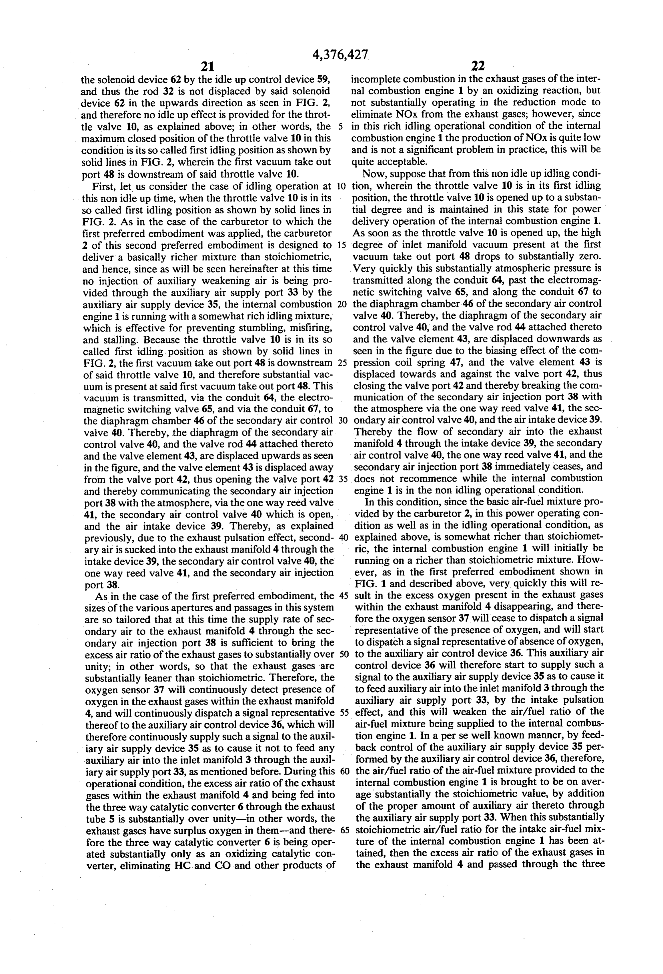
Page 17
way catalytic converter 6 will be approximately 1-i.e., called idling position as shown by the phantom lines in these exhaust gases will be near the stoichiometric con FIG. 2. As has been previously mentioned, the carbure dition-and therefore the three way catalytic converter tor 2 is designed to deliver a basically richer mixture 6 will function properly and effectively in its three way than stoichiometric, and hence, since as will be seen catalytic mode of removing not only HC, CO, and other hereinafter at this time no injection of auxiliary weaken products of incomplete combustion from the exhaust ing air is being provided through the auxiliary air sup gases by an oxidising reaction, but also of purifying the ply port 33 by the auxiliary air supply device 35, the exhaust gases of NOx by a reducing reaction. internal combustion engine 1 is running with a some Thus, as has been explained above, in the case of non what rich idling mixture, which is effective for prevent idle up operation, the transition between the idling 10 ing stumbling, misfiring, and stalling. Because the throt mode of operation, wherein the internal combustion tle valve 10 is in its so called second idling position as engine 1 is operated with an idling air-fuel mixture sub shown by phantom lines in FIG. 2, the second vacuum stantially richer than stoichiometric and the three way take out port 49 is downstream of said throttle valve 10, catalytic converter 6 is operated substantially only in its and therefore substantial vacuum is present at said sec oxidizing mode of operation and no auxiliary air is sup 15 ond vacuum take out port 49. The vacuum is transmit plied through the auxiliary air supply port 33 while ted, via the conduit 66, the electromagnetic switching secondary air is supplied through the secondary air valve 65 whose ports a and b are as stated above com injection port 38, and the non idling mode of operation, municated to one another at this time, and via the con wherein the internal combustion engine 1 is operated duit 67, to the diaphragm chamber 46 of the secondary with an air-fuel mixture substantially stoichiometric and air control valve 40. Thereby, the diaphragm of the the three way catalytic converter 6 is operated in both secondary air control valve 40, and the valve rod 44 its oxidizing mode of operation and its reducing mode attached thereto and the valve element 43, are displaced of operation and auxiliary air is supplied through the upwards as seen in the figure, and the valve element 43 auxiliary air supply port 33 while no secondary air is is displaced away from the valve port 42, thus opening supplied through the secondary air injection port 38, is 25 the valve port 42 and thereby communicating the sec performed quickly, reliably, and simply, according to ondary air injection port 38 with the atmosphere, via the function of the shown second preferred embodiment the one way reed valve 41, the secondary air control of the air/fuel ratio control system according to the valve 40 which is open, and the air intake device 39. present invention, as well as according to the function Thereby, as explained previously, due to the exhaust of the previously shown first embodiment, 30 pulsation effect, secondary air is sucked into the exhaust Idle Up Operation manifold 4 through the intake device 39, the secondary air control valve 40, the one way reed valve 41, and the
Now, on the other hand, suppose that based upon the secondary air injection port 38.
output signals from the air conditioner compressor As has also been previously stated, the sizes of the switch 60 and/or the power steering pump switch 61, 35 various apertures and passages in this system are so etc., the idle up control device 59 is deciding that idle tailored that at this time the supply rate of secondary air up action needs to be provided for the internal combus to the exhaust manifold 4 through the secondary air tion engine 1, and accordingly the idle up control de injection port 38 is sufficient to bring the excess air ratio vice 59 is providing actuating electrical energy for the of the exhaust gases to substantially over unity; in other electromagnetic switching valve 65 and for the solenoid words, so that the exhaust gases are substantially leaner device 62. In this condition, the port a of the electro than stoichiometric. Therefore, the oxygen sensor 37 magnetic switching valve 65 is communicated to the will continuously detect presence of oxygen in the ex port b thereof, while the port c is not communicated to haust gases within the exhaust manifold 4, and will anything. Therefore in this idle up condition any vac continuously dispatch a signal representative thereof to uum which is present at the second vacuum take out 45 the auxiliary air control device 36, which will therefore port 49 is transmitted via the conduit 66, the electro continuously supply such a signal to the auxiliary air magnetic switching valve 65, and the conduit 67 to the supply device 35 as to cause it not to feed any auxiliary diaphragm chamber 46 of the diaphragm device 45 of air into the inlet manifold 3 through the auxiliary air the sedondary air control valve 40. Further, actuating supply port 33, as mentioned above. Further, during electrical energy is provided to the solenoid device 62 50 this operational condition, the excess air ratio of the by the idle up control device 59, and thus the rod 32 is exhaust gases within the exhaust manifold 4 and being displaced by said solenoid device 62 in the upwards fed into the three way catalytic converter 6 through the direction as seen in FIG. 2, and therefore an idle up exhaust tube 5 is substantially over unity-in other effect is provided for the throttle valve 10, as explained words, the exhaust gases have surplus oxygen in them previously; in other words, the maximum closed posi 55 -and therefore the three way catalytic converter 6 is tion of the throttle valve 10 in this condition is its so being operated substantially only as an oxidizing cata called second idling or idle up position as shown by the lytic converter, eliminating HC and CO and other prod phantom lines in FIG. 2, wherein the first vacuum take ucts of incomplete combustion in the exhaust gases of out port 48 is in fact upstream of said throttle valve 10, the internal combustion engine 1 by an oxidizing reac but the second vacuum take out port 49 is just down 60 tion, but not substantially operating in the reduction stream of said throttle valve 10. Further, in this idle up mode to eliminate NOx from the exhaust gases; how condition any vacuum which is present at the second ever, since in this rich idle up idling operational condi vacuum take out port 49 is transmitted, via the conduit tion of the internal combustion engine 1 the production 66, the electromagnetic switching valve 65, and the of NOx is quite low and is not a significant problem in conduit 67, to the diaphragm chamber 46 of the dia 65 practice, this will be quite acceptable. phragm device 45 of the secondary air control valve 40. Now, suppose that from this idle up idling condition, First, let us consider the case of idling operation at wherein the throttle valve 10 is in its second or idle up this idle up time, when the throttle valve 10 is in its so idling position, the throttle valve 10 is opened up to a
Page 18
substantial degree and is maintained in this state for ture substantially richer than stoichiometric and the power delivery operation of the internal combustion three way catalytic converter 6 is operated substantially engine 1. As soon as the throttle valve 10 is opened up, only in its oxidizing mode of operation and no auxiliary the high degree of inlet manifold vacuum present at the air is supplied through the auxiliary air supply port 33 second vacuum take out port 49 drops to substantially - while secondary air is supplied through the secondary zero. Very quickly this substantially atmospheric pres air injection port 38, and the non idling mode of opera sure is transmitted via the conduit 66, the electromag tion, wherein the internal combustion engine 1 is oper netic switching valve 65, and the conduit 67 to the ated with an air-fuel mixture substantially stoichiomet diaphragm chamber 46 of the secondary air control ric and the three way catalytic converter 6 is operated valve 40. Thereby, the diaphragm of the secondary air 10 in both its oxidizing mode of operation and its reducing control valve 40, and the valve rod 44 attached thereto mode of operation and auxiliary air is supplied through and the valve element 43, are displaced downwards as the auxiliary air supply port 33 while no secondary air is seen in the figure due to the biasing effect of the com supplied through the secondary air injection port 38, is pression coil spring 47, and the valve element 43 is performed quickly, reliably, and simply, according to displaced towards and against the valve port 42, thus 15 the function of the shown second preferred embodiment closing the valve port 42 and thereby breaking the com of the air/fuel ratio control system according to the munication of the secondary air injection port 38 with present invention.
the atmosphere via the one way reed valve 41, the sec In summary, as will be clear from the above, in the ondary air control valve 40, and the air intake device 39. operation of the shown second preferred embodiment Thereby the flow of secondary air into the exhaust 20 of the air/fuel ratio control system according to the manifold 4 through the intake device 39, the secondary present invention, as well as in the function of the first air control valve 40, the one way reed valve 41, and the preferred embodiment, in both the non idle up mode of secondary air injection port 38 immediately ceases, and operation thereof, and the idle up mode of operation does not recommence while the internal combustion thereof; when the throttle valve 10 is in its idling posi engine 1 is in the non idling operational condition. 25 tion (respectively either the non idle up idling position In this condition, since the basic air-fuel mixture pro or the idle up idling position) then the internal combus vided by the carburetor 2, in this power operating con tion engine 1 is operated with an air-fuel mixture with dition as well as in the idle up idling operational condi an air/fuel ratio which is substantially richer than the tion, as explained above, is somewhat richer than stoi stoichiometric one, which is effective for preventing chiometric, the internal combustion engine 1 will ini 30 stumbling, misfiring, and stalling of said internal com tially be running on a richer than stoichiometric mix bustion engine 1 during idling; while, on the other hand, ture. However, very quickly this will result in the ex when the throttle valve 10 is moved away from its cess oxygen present in the exhaust gases within the idling position (whichever of the above non idle up or exhaust manifold 4 disappearing, and therefore the oxy idle up idling positions said idling position may respec gen sensor 37 will cease to dispatch a signal representa 35 tively currently be) by even a small amount, then the tive of the presence of oxygen, and will start to dispatch internal combustion engine 1 is operated with an air-fuel a signal representative of absence of oxygen, to the mixture with an air/fuel ratio which is substantially auxiliary air control device 36. This auxiliary air control stoichiometric, which is effective for promoting proper device 36 will therefore start to supply such a signal to operation of the three way catalytic converter 6 in its the auxiliary air supply device 35 as to cause it to feed, three way operational mode.
by the intake pulsation effect, auxiliary air into the inlet manifold 3 through the auxiliary air supply port 33, and Construction of the Third Preferred Embodiment this will weaken the air/fuel ratio of the air-fuel mixture In FIG. 3, there is shown a third preferred embodi being supplied to the internal combustion engine 1. In a ment of the air/fuel ratio control system according to perse well known manner, by feedback control of the 45 the present invention, in a fashion similar to FIG. 1 and auxiliary air supply device 35 performed by the auxil FIG. 2. In FIG. 3, parts of the third preferred embodi iary air control device 36, therefore, the air/fuel ratio of ment shown, which correspond to parts of the first and the air-fuel mixture provided to the internal combustion second preferred embodiments shown in FIG. 1 and in engine 1 is brought to be substantially the stoichiomet FIG. 2, and which have the same functions, are desig ric value, by addition of the proper amount of auxiliary 50 nated by the same reference numerals and symbols as in air thereto through the auxiliary air supply port 33. those figures.
When this substantially stoichiometric air/fuel ratio for In this figure, there is shown an internal combustion the intake gases of the internal combustion engine 1 has engine 1 which is equipped with the third preferred been attained, then the excess air ratio of the exhaust embodiment of the air/fuel ratio control system accord gases in the exhaust manifold 4 and passed through the 55 ing to the present invention, and also there are shown three way catalytic converter 6 will be approximately various other control mechanisms associated therewith. 1-i.e., these exhaust gases will be near the stoichiomet As in the previously shown first and second embodi ric condition-and therefore the three way catalytic ments, the reference numeral 2 denotes a carburetor converter 6 will function properly and effectively in its which supplies fuel/air mixture to said internal combus three way catalytic mode of removing not only HC, 60 tion engine 1 through an intake manifold 3. The fuel/air CO, and other products of incomplete combustion from mixture is combusted in the combustion chambers, not the exhaust gases by an oxidising reaction, but also of shown, of the internal combustion engine 1, and the purifying the exhaust gases of NOx by a reducing reac exhaust gases resulting from this combustion are ex tion. hausted through an exhaust manifold 4 into an exhaust Thus, as has been explained above, in the case of idle 65 tube 5, at an intermediate part of which there is fitted a up operation, the transition between the idle up idling three-way catalytic converter 6 of a perse well known mode of operation, wherein the internal combustion sort; the exhaust tube 5 and the three-way catalytic engine 1 is operated with an idle up idling air-fuel mix converter 6 are only shown schematically in FIG. 3,
Page 19
because the details of their construction are not rele Now the arrangements for performing so called "idle Vant. up' of the carburetor 2, which are in fact the same as in The construction of the carburetor 2 will now be the first preferred embodiment, will be explained. Cer described. This carburetor 2 is different from the carbu tain parts thereof are shown in FIG.3 by dashed lines retor 2 used with the first and second preferred embodi- 5 because they are in fact located outside the main body ments described above, because of additional air bleed of the carburetor 2, behind the throat 7 from the point ing arrangements provided thereto, as will be seen later. of view of the figure. To the throttle shaft 9 there is An air passage or throat 7 is formed through the body of fixed a throttle lever 26, which extends upwards in the the carburetor 2, and a large venturi 8 is fitted at an figure, and the upper end of which is formed with a lug upstream position in this throat 7. Downstream of the 27. An idle up lever 29 of a generally L shape is pivot large venturi 8 within the carburetor throat 7 there is ally attached to the body of the carburetor 2 by a pivot fitted a butterfly type throttle valve 10, which is fixed to pin 28, and an adjusting screw 30 fitted in the end of one a throttle shaft 9 which is rotatably mounted in the arm of this idle up lever 29 abuts against the lug 27. In walls of the throat 7, and which can rotate between a this first shown constructional example, the end of the position as seen in solid lines in the figure in which it other arm of the idle up lever 29 is connected, via a rod almost completely interrupts flow of gas through the 32, to the diaphragm (not particularly shown) of a dia throat 7, and a position in which it is quite wide open. phragm device 31, whose body is fixed to the body of Within the large venturi 8 there is fitted a small venturi the carburetor 2, although this is not shown in the fig
11, and within the small venturi 11 a main fuel nozzle 12 Thus, when the diaphragm chamber (not shown) of opens. 20
The carburetor 2 is provided with a float chamber 13, the diaphragm device 31 is not supplied with vacuum, and liquid fuel such as gasoline is kept at a predeter thenin the idle up lever 29 and the adjusting screw 30 are their positions as shown by dashed lines in the figure, mined constant level within this float chamber by a float and in this condition when the accelerator pedal (not and valve mechanism, not particularly shown or de 25 shown) scribed here. Via a main fueljet 14, this fuel flows from 10 is released thisactuating or other means for the throttle valve throttle valve 10 can return to its so the float chamber 13 into a main fuel passage 15, which called first idling position as shown by solid lines in leads it to a well 16. In the well 16 there is provided an FIG. 3, with the lug 29 abutting against the adjusting air bleed tube 17 which is pierced with a plurality of screw 30 which is in its shown position. On the other small holes for admitting a constant basic quantity of 30 hand, when the diaphragm chamber (not shown) of the bleed air into the liquid fuel within the well 16 from the diaphragm device 31 is supplied with vacuum, then the atmosphere, via a main air bleed jet 18, in a per se con idle up lever 29 and the adjusting screw 30 are moved, ventional manner. via the rod 32, somewhat in the clockwise direction To the air bleed tube 17, at an intermediate point from their positions as shown by dashed lines in the thereof, there opens an auxiliary air bleed tube 71, 35 figure, and in this condition when the accelerator pedal which leads as will be explained later to the output side (not shown) or other actuating means for the throttle of an auxiliary air supply device 69, the input side of valve 10 is released this throttle valve 10 can only re which is communicated to atmosphere via a clean air turn to its position as shown by phantom lines in FIG. 3, supply assembly 68. According therefore as more or with the lug 29 abutting against the adjusting screw 30 less extra or auxiliary bleed air is admitted by the auxil in its new idle up position, somewhat to the left in FIG. iary air supply device 69 into the auxiliary air bleed tube 3 from its shown position. In other words, the throttle 71, so more or less total bleed air is mixed with the valve 10 can only return to a so called second idling or liquid fuel such as gasoline in the well 16, from the holes idle up position wherein said throttle valve 10 is a little in the air bleed tube 17. opened up from said first idling position and therefore The body of the carburetor 2 is further provided with 45 provides somewhat more idling fuel-air mixture for the a slow port 19 and an idle port 20, which are communi internal combustion engine 1 than would be provided in cated with one another. A part of the fuel flowing said first idling position.
through the main fuel passage 15 is diverted into a slow In this third preferred embodiment, the means pro fuel passage 21, which leads to the slow port 19 and the vided for weakening the basically rich air-fuel mixture idle port 20. At an intermediate part of the slow fuel 50 provided by the carburetor 2, as partly outlined above, passage 21 there opens a passage which leads to the are as follows. The auxiliary air bleed tube 71 in the atmosphere via a slow air bleedjet 22, and upstream of carburetor 2 is connected to the output side of an auxil this intermediate part there are fitted within the slow iary air supply device 69, the input side of which is fuel passage 21 a slow fuel jet 23 and an economizer jet connected to a clean air supply assembly 68 which may 24. Finally, the amount of fuel which is supplied into the 55 include an air filter and the like. The auxiliary air supply throat 7 of the carburetor 2 from the idle port 20 is device 69 comprises a valve device for metering the controlled by an idle adjust screw 25, whose pointed amount of air flowing therethrough, and is itself perse end coapts with the idle port 20 to form a metering well known. The auxiliary air supply device 69 is con orifice. trolled by an auxiliary air control device 70, which The general construction of the carburetor 2, and of 60 receives a signal from an oxygen sensor 37 mounted in the various passages and jets therein, is that, provided the exhaust manifold 4. When and only when the oxy no auxiliary bleed air is admitted into the auxiliary air gen sensor 37 detects no oxygen in the exhaust gases bleed tube 71, the carburetor 2 tends to supply an air flowing through the exhaust manifold 4, the auxiliary fuel mixture whose air/fuel ratio is less than the stoi air supply device 69 is activated to feed air into the chiometric ratio; in other words, a rich air-fuel mixture, 65 auxiliary air bleed tube 71.
both in the idling operational condition and in the non The arrangements for providing secondary air to the idling operational condition wherein the throttle valve exhaust manifold 4, which are exactly the same as in the 10 is significantly opened. first preferred embodiment described above, will now
Page 20
be explained. Within the exhaust manifold 4 there is tromagnetic vacuum switching valve 53, then the port b provided a secondary air injection port 38. This second thereof is communicated to the port a thereof, while the ary air injection port 38 is located upstream of the oxy port c is not communicated to anything. gen sensor 37, so that when secondary air is being in The port c of the electromagnetic vacuum switching jected through the port 38 said oxygen sensor 37 is valve 53 is communicated to the atmosphere via an air responding to the oxygen content of exhaust gases into intake device 58 which may incorporate an air filter, which said air has been injected. Air is provided to the and the port b of the electromagnetic vacuum switching secondary air injection port 38, via a one way reed valve 53 is communicated directly, via a conduit 54, to valve 41 of a perse well known construction, through the diaphragm chamber of the diaphragm device 31, and under the control of a secondary air control valve O and is also communicated, via a conduit 55, a one way 40, which takes in this air from the atmosphere via an air valve 56, and a conduit 57, in that order, to a part of the intake device 39 which may incorporate an air filter. conduit 50 downstream of the throttling element 51, i.e. When the secondary air control valve 40 is opened, on the side of the throttling element 51 towards the secondary air is sucked into the exhaust manifold 4 by secondary air control valve 40. The one way valve 56 is the exhaust pulsation effect. The sizes of the various 15 so constructed that it will only allow fluid to flow there apertures and passages in this system are in this third through in the direction from the conduit 57 towards preferred embodiment also so tailored that, when the the conduit 55, and not vice versa; i.e., so that it will internal combustion engine 1 is idling and the secondary only allow vacuum to flow in the opposite direction. air control valve 40 is open, the supply rate of second Actuating electrical energy is selectively supplied to ary air to the exhaust manifold 4 through the secondary 20 the electromagnetic vacuum switching valve 53 by an air injection port 38 is sufficient to bring the excess air idle up control device 59 of a per se well known sort, ratio of the exhaust gases to substantially over unity; in which receives input signals from an air conditioner other words, so that the exhaust gases are substantially compressor switch 60 and/or from a power steering leaner than stoichiometric. pump switch 61, or the like, which depending upon The details of the internal construction of the second 25 these input signals decides when idle up of the internal ary air control valve 40 in this third preferred embodi combustion engine 1 should be performed, and which ment are exactly the same as those of the secondary air when it so decides supplies actuating electrical energy control valve 40 shown with regard to the description to the electromagnetic vacuum switching valve 53. of the first preferred embodiment of the air/fuel ratio Operation of the Third Preferred Embodiment control system according to the present invention, and 30 hence explanation thereof is omitted here in order to Now the operation of this first preferred embodiment avoid redundancy of description. Now the arrange of the air/fuel ratio control system according to the ments (which are also the same as in the first preferred present invention will be explained. embodiment described above) for providing actuating Non Idle Up Operation vacuum for the diaphragm device 31 which performs 35 the idle up of the carburetor 2 and for the diaphragm First, suppose that based upon the output signals from device 45 of the secondary air control valve 40 will be the air conditioner compressor switch 60 and/or the described. power steering pump switch 61, etc., the idle up control Two vacuum take out ports 48 and 49 are provided in device 59 is deciding that no idle up action needs to be the throat 7 of the carburetor 2, near the trailing edge of 40 provided for the internal combustion engine 1, and the throttle valve 10. The first vacuum take out port 48 accordingly the idle up control device 59 is not provid is so located that it is downstream of the throttle valve ing any actuating electrical energy for the electromag 10 when the throttle valve 10 is in its first idling posi netic switching valve 53. In this condition, the port b of tion, and becomes to be upstream of the throttle valve the electromagnetic switching valve 53 is communi 10 when the throttle valve 10 is opened slightly beyond 45 cated to the port c thereof and therethrough to atmo its first idling position. On the other hand, the second sphere, while the port a is not communicated to any vacuum take out port 49 is so located that it is down thing, and therefore atmospheric pressure is admitted to stream of the throttle valve 10 when the throttle valve the diaphragm chamber of the diaphragm device 31 (but 10 is in its second idling position or idle up position, and is not admitted to the conduit 50 via the conduit 57, due becomes to be upstream of the throttle valve 10 when 50 to the provision of the one way valve 56 which inter the throttle valve 10 is opened slightly beyond its sec cepts air flow in this direction). Thus the rod 32 is not ond idling or idle up position. Thus, in fact, the second displaced by said diaphragm device 31 in the upwards vacuum take out port 49 is located very close to, but a direction as seen in FIG. 3, and therefore no idle up little downstream of, the first vacuum take out port 48. effect is provided for the throttle valve 10, as explained The first vacuum take out port 48 is connected via a 55 above; in other words, the maximum closed position of conduit 50 to the diaphragm chamber 46 of the dia the throttle valve 10 in this condition is its so called first phragm device 45, and a throttling element 51 is inter idling position as shown by solid lines in FIG. 3, posed at an upstream part of the conduit 50. The second wherein the first vacuum take out port 48 is down vacuum take out port 49 is connected via a conduit 52 to stream of said throttle valve 10. Further, in this non idle a port a of an electromagnetic vacuum switching valve up condition any vacuum which is present at the first 53. vacuum take out port 48 is transmitted, via the throt The electromagnetic vacuum switching valve 53 has tling element 51 which delays its transmission for a three ports a, b, and c. When actuating electrical energy short time, to the diaphragm chamber 46 of the dia is not being supplied to the electromagnetic vacuum phragm device 45 of the secondary air control valve 40. switching valve 53, then the port b thereof is communi 65 First, let us consider the case of idling operation at cated to the port c thereof, while the port a is not com this non idle up time, when the throttle valve 10 is in its municated to anything; and, on the other hand, when so called first idling position as shown by solid lines in actuating electrical energy is being supplied to the elec FIG. 3. As has been previously mentioned, the carbure
Page 21
tor 2 is designed to deliver a basically richer mixture degree of inlet manifold vacuum present at the first than stoichiometric, and hence, since as will be seen vacuum take out port 48 drops to substantially zero. hereinafter at this time no injection of auxiliary weaken Very quickly this substantially atmospheric pressure is ing bleed air is being provided through the auxiliary air transmitted past the throttling element 51 along the bleed tube 71 by the auxiliary air supply device 69, the conduit 50 to the diaphragm chamber 46 of the second internal combustion engine 1 is running with a some ary air control valve 40. Thereby, the diaphragm of the what rich idling mixture, which is effective for prevent secondary air control valve 40, and the valve rod 44 ing stumbling, misfiring, and stalling. Because the throt attached thereto and the valve element 43, are displaced tle valve 10 is in its so called first idling position as downwards as seen in the figure due to the biasing effect shown by solid lines in FIG. 3, the first vacuum take out of the compression coil spring 47, and the valve element port 48 is downstream of said throttle valve 10, and 43 is displaced towards and against the valve port 42, therefore substantial vacuum is present at said first vac thus closing the valve port 42 and thereby breaking the uum take out port 48. This vacuum is transmitted, via communication of the secondary air injection port 38 the throttling element 51 which does not substantially with the atmosphere via the one way reed valve 41, the disturb it, and via the conduit 50, to the diaphragm 5 secondary air control valve 40, and the air intake device chamber 46 of the secondary air control valve 40. 39. Thereby the flow of secondary air into the exhaust Thereby, the diaphragm of the secondary air control manifold 4 through the intake device 39, the secondary valve 40, and the valve rod 44 attached thereto and the air control valve 40, the one way reed valve 41, and the valve element 43, are displaced upwards as seen in the secondary air injection port 38 immediately ceases, and figure, and the valve element 43 is displaced away from does not recommence while the internal combustion the valve port 42, thus opening the valve port 42 and engine 1 is in the non idling operational condition. thereby communicating the secondary air injection port In this condition, since the basic air-fuel mixture pro 38 with the atmosphere, via the one way reed valve 41, vided by the carburetor 2, in this power operating con the secondary air control valve 40 which is open, and dition as well as in the idling operational condition, as the air intake device 39. Thereby, as explained previ 25 explained above, is somewhat richer than stoichiomet ously, due to the exhaust pulsation effect, secondary air ric, the internal combustion engine 1 will initially be is sucked into the exhaust manifold 4 through the intake running on a richer than stoichiometric mixture. How device 39, the secondary air control valve 40, the one ever, very quickly this will result in the excess oxygen way reed valve 41, and the secondary air injection port present in the exhaust gases within the exhaust manifold 38. 30 4 disappearing, and therefore the oxygen sensor 37 will As has also been explained, the sizes of the various cease to dispatch a signal representative of the presence apertures and passages in this system are so tailored that of oxygen, and will start to dispatch a signal representa at this time the supply rate of secondary air to the ex tive of absence of oxygen, to the auxiliary air control haust manifold 4 through the secondary air injection device 70. This auxiliary air control device 70 will port 38 is sufficient to bring the excess air ratio of the 35 therefore start to supply such a signal to the auxiliary air exhaust gases to substantially over unity; in other supply device 69 as to cause it to feed auxiliary air into words, so that the exhaust gases are substantially leaner the fuel in the well 16 through the auxiliary air bleed than stoichiometric. Therefore, the oxygen sensor 37 tube 71, and this will weaken the air/fuel ratio of the will continuously detect presence of oxygen in the ex air-fuel mixture being supplied to the internal combus haust gases within the exhaust manifold 4, and will tion engine 1. In a perse well known manner, by feed continuously dispatch a signal representative thereof to back control of the auxiliary air supply device 69 per the auxiliary air control device 70, which will therefore formed by the auxiliary air control device 70, therefore, continuously supply such a signal to the auxiliary air the air/fuel ratio of the air-fuel mixture provided to the supply device 69 as to cause it not to feed any auxiliary internal combustion engine it is brought to be substan air into the intake system of the internal combustion 45 tially the stoichiometric value, by addition of the proper engine 1 through the auxiliary air bleed tube 71, as amount of auxiliary air thereto through the auxiliary air mentioned above. Further, during this operational con bleed tube 71. When this substantially stoichiometric dition, the excess air ratio of the exhaust gases within air/fuel ratio for the intake gases of the internal combus the exhaust manifold 4 and being fed into the three way tion engine 1 has been attained, then the excess air ratio catalytic converter 6 through the exhaust tube 5 is sub 50 of the exhaust gases in the exhaust manifold 4 and stantially over unity-in other words, the exhaust gases passed through the three way catalytic converter 6 will have surplus oxygen in them-and therefore the three be approximately 1-i.e., these exhaust gases will be way catalytic converter 6 is being operated substan near the stoichiometric condition-and therefore the tially only as an oxidizing catalytic converter, eliminat three way catalytic converter 6 will function properly ing HC and CO and other products of incomplete com 55 and effectively in its three way catalytic mode of re bustion in the exhaust gases of the internal combustion moving not only HC, CO, and other products of incom engine 1 by an oxidizing reaction, but not substantially plete combustion from the exhaust gases by an oxidising operating in the reduction mode to eliminate NOx from reaction, but also of purifying the exhaust gases of NOx the exhaust gases; however, since in this rich idling by a reducing reaction.
operational condition of the internal combustion engine 60 Thus, as has been explained above, in the case of non 1 the production of NOx is quite low and is not a signifi idle up operation, the transition between the idling cant problem in practice, this will be quite acceptable. mode of operation, wherein the internal combustion Now, suppose that from this non idle up idling condi engine 1 is operated with an idling air-fuel mixture sub tion, wherein the throttle valve 10 is in its first idling stantially richer than stoichiometric and the three way position, the throttle valve 10 is opened up to a substan 65 catalytic converter 6 is operated substantially only in its tial degree and is maintained in this state for power oxidizing mode of operation and no auxiliary air is sup delivery operation of the internal combustion engine 1. plied through the auxiliary air bleed tube 71 while sec As soon as the throttle valve 10 is opened up, the high ondary air is supplied through the secondary air injec
Page 22
tion port 38, and the non idling mode of operation, position as shown by phantom lines in FIG. 3, the sec wherein the internal combustion engine 1 is operated ond vacuum take out port 49 is downstream of said with an air-fuel mixture substantially stoichiometric and throttle valve 10, and therefore substantial vacuum is the three way catalytic converter 6 is operated in both present at said second vacuum take out port 49. This its oxidizing mode of operation and its reducing mode vacuum is transmitted, via the conduit 52, the electro of operation and auxiliary air is supplied through the magnetic switching valve 53 whose ports a and b are as auxiliary air bleed tube 71 while no secondary air is stated above communicated to one another at this time, supplied through the secondary air injection port 38, is performed quickly, reliably, and simply, according to via the conduits 54 and 55, via the one way valve 56, and via the conduits 57 and 50, to the diaphragm cham the function of the shown third preferred embodiment 10 ber 46 of the secondary air control valve 40 (not being of the air/fuel ratio control system according to the substantially attenuated by leakage past the throttling present invention. element 51 to the first vacuum take out port 48, due to Idle Up Operation the high flow resistance of said throttling element 51). Thereby, the diaphragm of the secondary air control
Now, on the other hand, suppose that based upon the 15 valve 40, and the valve rod 44 attached thereto and the output signals from the air conditioner compressor valve element 43, are displaced upwards as seen in the switch 60 and/or the power steering pump switch 61, figure, and the valve element 43 is displaced away from etc., the idle up control device 59 is deciding that idle the valve port 42, thus opening the valve port 42 and up action needs to be provided for the internal combus thereby communicating the secondary air injection port tion engine 1, and accordingly the idle up control de 20 38 with the atmosphere, via the one way reed valve 41, vice 59 is providing actuating electrical energy for the the secondary air control valve 40 which is open, and electromagnetic switching valve 53. In this condition, the air intake device 39. Thereby, as explained previ the port a of the electromagnetic switching valve 53 is ously, due to the exhaust pulsation effect, secondary air communicated to the port b thereof, while the port c is is sucked into the exhaust manifold 4 through the intake not communicated to anything. Therefore, when the 25 device 39, the secondary air control valve 40, the one throttle pedal or other throttle actuating device of the way reed valve 41, and the secondary air injection port vehicle incorporating this system is released, so as to 38.
close the throttle valve 10, the high amount of vacuum As has also been previously stated, the sizes of the which is immediately thus caused to be present at the various apertures and passages in this system are so second vacuum take out port 49 is transmitted, via the 30 tailored that at this time the supply rate of secondary air vacuum conduit 52, to the port a of the electromagnetic to the exhaust manifold 4 through the secondary air switching valve 53, whence this vacuum is transmitted injection port 38 is sufficient to bring the excess air ratio to the diaphragm chamber of the diaphragm device 31 of the exhaust gases to substantially over unity; in other and actuates the diaphragm (not shown) thereof. Thus words, so that the exhaust gases are substantially leaner the rod 32 is displaced by said diaphragm device 31 in 35 than stoichiometric. Therefore, the oxygen sensor 37 the upwards direction as seen in FIG. 3, and therefore will continuously detect presence of oxygen in the ex an idle up effect is provided for the throttle valve 10, as haust gases within the exhaust manifold 4, and will explained previously; in other words, the maximum continuously dispatch a signal representative thereof to closed position of the throttle valve 10 in this condition the auxiliary air control device 70, which will therefore is its so called second idling or idle up position as shown continuously supply such a signal to the auxiliary air by the phantom lines in FIG. 3, wherein the first vac supply device 69 as to cause it not to feed any auxiliary uum take out port 48 is in fact upstream of said throttle air into the inlet manifold 3 through the auxiliary air valve 10, but the second vacuum take out port 49 is just bleed tube 71, as mentioned above. Further, during this downstream of said throttle valve 10. Further, in this operational condition, the excess air ratio of the exhaust idle up condition any vacuum which is present at the 45 gases within the exhaust manifold 4 and being fed into second vacuum take out port 49 is transmitted, via the the three way catalytic converter 6 through the exhaust conduit 52, the electromagnetic switching valve 53, the tube 5 is substantially over unity-in other words, the conduit 54, the conduit 55, the one way valve 56, the exhaust gases have surplus oxygen in them-and there conduit 57, and the conduit 50, to the diaphragm cham fore the three way catalytic converter 6 is being oper ber 46 of the diaphragm device 45 of the secondary air 50 ated substantially only as an oxidizing catalytic con control valve 40. In this connection, by the way, sub verter, eliminating HC and CO and other products of stantial escape of such vacuum through the upstream incomplete combustion in the exhaust gases of the inter part of the conduit 50 in the reverse direction through nal combustion engine 1 by an oxidizing reaction, but the first vacuum take out port 48 is prevented by the not substantially operating in the reduction mode to provision of the throttling element 51. 55 eliminate NOx from the exhaust gases; however, since First, let us consider the case of idling operation at in this rich idle up idling operational condition of the this idle up time, when the throttle valve 10 is in its so internal combustion engine 1 the production of NOx is called second idling position as shown by the phantom quite low and is not a significant problem in practice, lines in FIG. 3. As has been previously mentioned, the this will be quite acceptable.
carburetor 2 is designed to deliver a basically richer Now, suppose that from this idle up idling condition, mixture than stoichiometric, and hence, since as will be wherein the throttle valve 10 is in its second or idle up seen hereinafter at this time no injection of auxiliary idling position, the throttle valve 10 is opened up to a weakening bleed air is being provided through the aux substantial degree and is maintained in this state for iliary air bleed tube 71 by the auxiliary air supply device power delivery operation of the internal combustion 69, the internal combustion engine 1 is running with a 65 engine 1. As soon as the throttle valve 10 is opened up, somewhat rich idling mixture, which is effective for the high degree of inlet manifold vacuum present at the preventing stumbling, misfiring, and stalling. Because second vacuum take out port 49 drops to substantially the throttle valve 10 is in its so called second idling zero. Very quickly this substantially atmospheric pres
Page 23
sure is transmitted via the conduit 52, the electromag air is supplied through the auxiliary air bleed tube 71 netic switching valve 53 whose ports a and b are com while secondary air is supplied through the secondary municated to one another at this time, via the conduits air injection port 38, and the non idling mode of opera 54 and 55, via the one way valve 56, and via the con tion, wherein the internal combustion engine 1 is oper duits 57 and 50, to the diaphragm chamber 46 of the ated with an air-fuel mixture substantially stoichiomet secondary air control valve 40. Thereby, the diaphragm ric and the three way catalytic converter 6 is operated of the secondary air control valve 40, and the valve rod in both its oxidizing mode of opertion and its reducing 44 attached thereto and the valve element 43, are dis mode of operation and auxiliary air is supplied through placed downwards as seen in the figure due to the bias the auxiliary air bleed tube 71 while no secondary air is ing effect of the compression coil spring 47, and the 10 supplied through the secondary air injection port 38, is valve element 43 is displaced towards and against the performed quickly, reliably, and simply, according to valve port 42, thus closing the valve port 42 and thereby the function of the shown first preferred embodiment of breaking the communication of the secondary air injec the air/fuel ratio control system according to the pres tion port 38 with the atmosphere via the one way reed ent invention.
valve 41, the secondary air control valve 40, and the air 15 In summary, as will be clear from the above, in both intake device 39. Thereby the flow of secondary air into the non idle up mode of operation of the shown third the exhaust manifold 4 through the intake device 39, the preferred embodiment of the air/fuel ratio control sys secondary air control valve 40, the one way reed valve tem according to the present invention, and the idle up 41, and the secondary air injection port 38 immediately mode of operation thereof: when the throttle valve 10 is ceases, and does not recommence while the internal in its idling position (respectively either the non idle up combustion engine 1 is in the non idling operational idling position or the idle up idling position) then the condition. internal combustion engine 1 is operated with an air-fuel In this condition, since the basic air-fuel mixture pro mixture with an air/fuel ratio which is substantially vided by the carburetor 2, in this power operating con richer than the stoichiometric one, which is effective dition as well as in the idle up idling operational condi 25 for preventing stumbling, misfiring, and stalling of said tion, as explained above, is somewhat richer than stoi internal combustion engine 1 during idling; while, on chiometric, the internal combustion engine 1 will ini the other hand, when the throttle valve 10 is moved tially be running on a richer than stoichiometric mix away from its idling position (whichever of the above ture. However, very quickly this will result in the ex non idle up or idle up idling positions said idling posi cess oxygen present in the exhaust gases within the tion may respectively currently be) by even a small exhaust manifold 4 disappearing, and therefore the oxy amount, then the internal combustion engine 1 is oper gen sensor 37 will cease to dispatch a signal representa ated with an air-fuel mixture with an air/fuel ratio tive of the presence of oxygen, and will start to dispatch which is substantially stoichiometric, which is effective a signal representative of absence of oxygen, to the for promoting proper operation of the three way cata auxiliary air control device 70. This auxiliary air control 35 lytic converter 6 in its three way operational mode. device 70 will therefore start to supply such a signal to Construction of the Fourth Preferred Embodiment the auxiliary air supply device 69 as to cause it to feed auxiliary bleed air into the fuel within the well 16 In FIG. 4, there is shown a fourth preferred embodi through the auxiliary air bleed tube 71, and this will ment of the air/fuel ratio control system according to weaken the air/fuel ratio of the air-fuel mixture being the present invention, in a fashion similar to FIGS. 1-3. supplied to the internal combustion engine 1. In a perse In FIG. 4, parts of the fourth preferred embodiment well known manner, by feedback control of the auxil shown, which correspond to parts of the first through iary air supply device 69 performed by the auxiliary air third preferred embodiments shown in FIGS. 1-3, and control device 70, therefore, the air/fuel ratio of the which have the same functions, are designated by the air-fuel mixture provided to the internal combustion 45 same reference numerals and symbols as in those fig engine 1 is brought to be substantially the stoichiomet utes.
ric value, by addition of the proper amount of auxiliary In FIG. 4, there is again shown an internal combus air thereto through the auxiliary air bleed tube 71. tion engine 1, which is now equipped with a fourth When this substantially stoichiometric air/fuel ratio for preferred embodiment of the air/fuel ratio control sys the intake gases of the internal combustion engine 1 has 50 tem according to the present invention. This fourth been attained, then the excess air ratio of the exhaust preferred embodiment, in its difference from the first gases in the exhaust manifold 4 and passed through the preferred embodiment, combines the features of the three way catalytic converter 6 will be approximately second and of the third preferred embodiments. 1-i.e., these exhaust gases will be near the stoichiomet The reference numeral 2 again denotes a carburetor ric condition-and therefore the three way catalytic 55 which supplies fuel/air mixture to said internal combus converter 6 will function properly and effectively in its tion engine 1 through an intake manifold 3. The fuel/air three way catalytic mode of removing not only HC, mixture is combusted in the combustion chambers, not CO, and other products of incomplete combustion from shown, of the internal combustion engine 1, and the the exhaust gases by an oxidising reaction, but also of exhaust gases resulting from this combustion are again purifying the exhaust gases of NOx by a reducing reac 60 exhausted through an exhaust manifold 4 into an ex tion. haust tube 5, at an intermediate part of which there is Thus, as has been explained above, in the case of idle again fitted a three-way catalytic converter 6 of a perse up operation, the transition between the idle up idling well known sort; the exhaust tube 5 and the three-way mode of operation, wherein the internal combustion catalytic converter 6 are again only shown schemati engine 1 is operated with an idle up idling air-fuel mix 65 cally in FIG.2, because the details of their construction ture substantially richer than stoichiometric and the are not relevant.
three way catalytic converter 6 is operated substantially The details of the internal construction of the carbu only in its oxidizing mode of operation and no auxiliary retor 2 are exactly the same as those of the carburetor 2
Page 24
shown with regard to the description of the third pre sembly 68, the auxiliary air control device 70, and the ferred embodiment of the air/fuel ratio control system oxygen sensor 37, is exactly the same as in the third according to the present invention, incorporating an preferred embodiment of the air/fuel ratio control de auxiliary bleed air tube 71, and hence explanation vice according to the present invention shown in FIG. thereof is omitted here in order to avoid redundancy of 5 3, and hence explanation thereof is omitted here in description. The general construction of the carburetor order to avoid redundancy of description. 2, and of the various passages and jets therein, again Within the exhaust manifold 4 there is again provided with regard to this second preferred embodiment, is a secondary air injection port 38, upstream of the oxy that the carburetor 2 tends to supply an air-fuel mixture gen sensor 37, which in exactly the same way as in the whose air/fuel ratio is less than the stoichiometric ratio, O first through third preferred embodiments shown in when no extra bleed air is being admitted through the FIGS. 1 through 3 is selectively provided with air via a auxiliary bleed air tube 71; in other words, a rich air-fuel one way reed valve 41 of a perse well known construc mixture, both in the idling operational condition and in tion, through and under the control of a secondary air the non-idling operational condition wherein the throt control valve 40, which takes in this air from the atmo tle valve 10 is significantly opened. 15 sphere via an air intake device 39 which may incorpo Now the arrangements for performing so called "idle rate an air filter. When the secondary air control valve up' of the carburetor 2 will be explained, which are in 40 is opened, again, secondary air is sucked into the this case the same as in the case of the second preferred exhaust manifold 4 by the exhaust pulsation effect. embodiment. As before, certain parts thereof are shown Again, the sizes of the various apertures and passages in in FIG. 2 by dashed lines because they are in fact lo this system are so tailored that, when the internal com cated outside the main body of the carburetor 2, behind bustion engine 1 is idling and the secondary air control the throat 7 from the point of view of the figure. To the valve 40 is open, the supply rate of secondary air to the throttle shaft 9 there is fixed a throttle lever 26, which exhaust manifold 4 through the secondary air injection extends upwards in the figure, and the upper end of port 38 is sufficient to bring the excess air ratio of the which is fomed with a lug 27. An idle up lever 29 of a 25 exhaust gases to substantially over unity; in other generally L. shape is pivotally attached to the body of words, so that the exhaust gases are substantially leaner the carburetor 2 by a pivot pin 28, and an adjusting than stoichiometric.
screw 30 fitted in the end of one arm of this idle up lever The details of the internal construction of the second 29 abuts against the lug 27. In this construction, the end ary air control valve 40 are exactly the same as those of of the other arm of the idle up lever 29 is connected to 30 the secondary air control valve 40 shown with regard to the plunger 63 of a solenoid device 62, whose body is the description of the first preferred embodiment of the fixed to the body of the carburetor 2, although this is air/fuel ratio control system according to the present not shown in the figure. invention, and hence explanation thereof is omitted here Thus, when the coil (not shown) of the solenoid de in order to avoid redundancy of description. Now the vice 62 is not supplied with actuating electrical energy, 35 arrangements for providing actuating vacuum for the then the idle up lever 29 and the adjusting screw 30 are diaphragm device 45 of the secondary air control valve in their positions as shown by dashed lines in the figure, 40, which are substantially the same as in the second and in this condition when the accelerator pedal (not preferred embodiment, will be described. shown) or other actuating means for the throttle valve As before, two vacuum take out ports 48 and 49 are 10 is released this throttle valve 10 can return to its so provided in the throat 7 of the carburetor 2, near the called first idling position as shown by solid lines in trailing edge of the throttle valve 10. The first vacuum FIG. 4, with the lug 29 abutting against the adjusting take out port 48 is so located that it is downstream of the screw 30 which is in its shown position. On the other throttle valve 10 when the throttle valve 10 is in its first hand, when the coil (not shown) of the solenoid device idling position, and becomes to be upstream of the 62 is supplied with actuating electrical energy, then the 45 throttle valve 10 when the throttle valve 10 is opened idle up lever 29 and the adjusting screw 30 are moved, slightly beyond its first idling position. On the other via the rod 32, somewhat in the clockwise direction hand, the second vacuum take out port 49 is so located from their positions as shown by dashed lines in the that it is downstream of the throttle valve 10 when the figure, and in this condition when the accelerator pedal throttle valve 10 is in its second idling position or idle (not shown) or other actuating means for the throttle 50 up position, and becomes to be upstream of the throttle valve 10 is released this throttle valve 10 can only re valve 10 when the throttle valve 10 is opened slightly turn to its position as shown by phantom lines in FIG. 4, beyond its second idling or idle up position. Thus, in with the lug 29 abutting against the adjusting screw 30 fact, the second vacuum take out port 49 is located very in its new idle up position, somewhat to the left in FIG. close to, but a little downstream of, the first vacuum 4 from its shown position. In other words, the throttle 55 take out port 48, in a fashion identical to that of the first valve 10 can only return to a so called second idling or preferred embodiment.
idle up position wherein said throttle valve 10 is a little The first vacuum take out port 48 is connected via a opened up from said first idling position and therefore conduit 64 to a port c of an electromagnetic vacuum provides somewhat more idling fuel-air mixture for the switching valve 65. The second vacuum take out port internal combustion engine 1 than would be provided in 49 is connected via a conduit 66 to another porta of said said first idling position. electromagnetic vacuum switching valve 65. And the In this fourth preferred embodiment, the construction port b of the electromagnetic vacuum switching valve of the system for selectively providing auxiliary air into 65 is communicated directly, via a conduit 67, to the the intake system of the internal combustion engine 1, in diaphragm chamber 46 of the diaphragm device 45 of order to weaken the somewhat richer than stoichiomet 65 the secondary air control valve 40. ric air-fuel mixture which is being provided by the car The communications between the ports a, b, and c of buretor 2, comprising the auxiliary air bleed tube 71, the the electromagnetic vacuum switching valve 65 are as auxiliary air supply device 69, the clean air supply as follows. When actuating electrical energy is not being
Page 25
supplied to the electromagnetic vacuum switching seen hereinafter at this time in fact no injection of auxil valve 65, then the port b thereof is communicated to the iary weakening air is being provided through the auxil port c thereof, while the port a is not communicated to iary air bleed pipe 71 by the auxiliary air supply device anything; and, on the other hand, when actuating elec 69, the internal combustion engine 1 is running with a trical energy is being supplied to the electromagnetic 5 somewhat rich idling mixture, which is effective for vacuum switching valve 65, then the port b thereof is preventing stumbling, misfiring, and stalling. Because communicated to the port a thereof, while the port c is the throttle valve 10 is in its so called first idling position not communicated to anything. as shown by solid lines in FIG. 4, the first vacuum take Actuating electrical energy is selectively supplied out port 48 is downstream of said throttle valve 10, and both to the electromagnetic vacuum switching valve 65 10 therefore substantial vacuum is present at said first vac and to the solenoid device 62, in parallel, by an idle up uum take out port 48. This vacuum is transmitted, via control device 59 of a sort identical to the one shown the conduit 64, the electromagnetic switching valve 65, with regard to the first through third preferred embodi and via the conduit 67, to the diaphragm chamber 46 of ments of the present invention, which receives input the secondary air control valve 40. Thereby, the dia signals from an air conditioner compressor switch 60 15 phragm of the secondary air control valve 40, and the and/or from a power steering pump switch 61, or the valve rod 44 attached thereto and the valve element 43, like, which depending upon these input signals decides are displaced upwards as seen in the figure, and the when idle up of the internal combustion engine 1 should valve element 43 is displaced away from the valve port be performed, and which when it so decides supplies 42, thus opening the valve port 42 and thereby commu actuating electrical energy both to the electromagnetic 20 nicating the secondary air injection port 38 with the vacuum switching valve 65 and to the solenoid device atmosphere, via the one way reed valve 41, the second 62. ary air control valve 40 which is open, and the air intake Thus it will be seen that this fourth preferred embodi device 39. Thereby, as explained previously, due to the ment of the air/fuel ratio control system according to exhaust pulsation effect, secondary air is sucked into the the present invention is in fact a combination of the 25 exhaust manifold 4 through the intake device 39, the second and the third embodiments, because of the use of secondary air control valve 40, the one way reed valve bleed air into the carburetor to weaken the primary 41, and the secondary air injection port 38. air-fuel mixture, and because of the use of an electrical As in the case of the first preferred embodiment, the actuator (the solenoid device 62) for performing idle up sizes of the various apertures and passages in this system of the carburetor 2. 3O are so tailored that at this time the supply rate of sec Operation of the Fourth Preferred Embodiment Non ondary air to the exhaust manifold 4 through the sec Idle Up Operation ondary air injection port 38 is sufficient to bring the excess air ratio of the exhaust gases to substantially over
First, suppose that based upon the output signals from unity; in other words, so that the exhaust gases are the air conditioner compressor switch 60 and/or the 35 substantially leaner than stoichiometric. Therefore, the power steering pump switch 61, etc., the idle up control oxygen sensor 37 will continuously detect presence of device 59 is deciding that no idle up action needs to be oxygen in the exhaust gases within the exhaust manifold provided for the internal combustion engine 1, and 4, and will continuously dispatch a signal representative accordingly the idle up control device 59 is not provid thereof to the auxiliary air control device 70, which will ing any actuating electrical energy for the solenoid 40 therefore continuously supply such a signal to the auxil device 62 or for the electromagnetic switching valve 65. iary air supply device 69 as to cause it not to feed any In this condition, the port b of the electromagnetic auxiliary air into the intake system of the internal com switching valve 65 is communicated to the port c bustion engine 1 via the auxiliary air bleed tube 71, as thereof, while the port a is not communicated to any mentioned before. During this operational condition, thing, and therefore in this non idle up condition any 45 the excess air ratio of the exhaust gases within the ex vacuum which is present at the first vacuum take out haust manifold 4 and being fed into the three way cata port 48 is transmitted, via the electromagnetic switch lytic converter 6 through the exhaust tube 5 is substan ing valve 65, to the diaphragm chamber 46 of the dia tially over unity-in other words, the exhaust gases phragm device 45 of the secondary air control valve 40. have surplus oxygen in them-and therefore the three Further, no actuating electrical energy is provided to 50 way catalytic converter 6 is being operated substan the solenoid device 62 by the idle up control device 59, tially only as an oxidizing catalytic converter, eliminat and thus the rod 32 is not displaced by said solenoid ing HC and CO and other products of incomplete com device 62 in the upwards direction as seen in FIG. 4, bustion in the exhaust gases of the internal combustion and therefore no idle up effect is provided for the throt engine 1 by an oxidizing reaction, but not substantially tle valve 10, as explained above; in other words, the 55 operating in the reduction mode to eliminate NOx from maximum closed position of the throttle valve 10 in this the exhaust gases; however, since in this rich idling condition is its so called first idling position as shown by operational condition of the internal combustion engine solid lines in FIG. 4, wherein the first vacuum take out 1 the production of NOx is quite low and is not a signifi port 48 is downstream of said throttle valve 10. cant problem in practice, this will be quite acceptable. First, let us consider the case of idling operation at 60 Now, suppose that from this non idle up idling condi this non idle up time, when the throttle valve 10 is in its tion, wherein the throttle valve 10 is in its first idling so called first idling position as shown by solid lines in position, the throttle valve 10 is opened up to a substan FIG. 4. As in the case of the carburetor to which the tial degree and is maintained in this state for power first preferred embodiment was applied, the carburetor delivery operation of the internal combustion engine 1. 2 of this fourth preferred embodiment is designed to 65 As soon as the throttle valve 10 is opened up, the high deliver a basically richer mixture than stoichiometric degree of inlet manifold vacuum present at the first (when no auxiliary bleed air is being supplied to the vacuum take out port 48 drops to substantially zero. auxiliary bleed air pipe 71), and hence, since as will be Very quickly this substantially atmospheric pressure is
Page 26
transmitted along the conduit 64, past the electromag ondary air is supplied through the secondary air injec netic switching valve 65, and along the conduit 67 to tion port 38, and the non idling mode of operation, the diaphragm chamber 46 of the secondary air control. wherein the internal combustion engine 1 is operated valve 40. Thereby, the diaphragm of the secondary air with an air-fuel mixture substantially stoichiometric and control valve 40, and the valve rod 44 attached thereto the three way catalytic converter 6 is operated in both and the valve element 43, are displaced downwards as its oxidizing mode of operation and its reducing mode seen in the figure due to the biasing effect of the com of operation and auxiliary air is supplied through the pression coil spring 47, and the valve element 43 is auxiliary air bleed tube 71 while no secondary air is displaced towards and against the valve port 42, thus supplied through the secondary air injection port 38, is closing the valve port 42 and thereby breaking the com O performed quickly, reliably, and simply, according to munication of the secondary air injection port 38 with the function of the shown fourth preferred embodiment the atmosphere via the one way reed valve 41, the sec of the air/fuel ratio control system according to the ondary air control valve 40, and the air intake device 39. present invention, as well as according to the function Thereby the flow of secondary air into the exhaust of the previously shown first through third embodi manifold 4 through the intake device 39, the secondary 15 ments.
air control valve 40, the one way reed valve 41, and the secondary air injection port 38 immediately ceases, and IDLE UPOPERATION does not recommence while the internal combustion Now, on the other hand, suppose that based upon the engine 1 is in the non idling operational condition. output signals from the air conditioner compressor In this condition, since the basic air-fuel mixture pro 20 switch 60 and/or the power steering pump switch 61, vided by the carburetor 2, in this power operating con etc., the idle up control device 59 is deciding that idle dition as well as in the idling operational condition, as up action needs to be provided for the internal combus explained above, is somewhat richer than stoichiomet tion engine 1, and accordingly the idle up control de ric, the internal combustion engine 1 will initially be vice 59 is providing actuating electrical energy for the running on a richer than stoichiometric mixture. How 25 electromagnetic switching valve 65 and for the solenoid ever, as in the first through third preferred embodi device 62. In this condition, the port a of the electro ments shown in FIGS. 1 through 3 and described magnetic switching valve 65 is communicated to the above, very quickly this will result in the excess oxygen port b thereof, while the port c is not communicated to present in the exhaust gases within the exhaust manifold anything. Therefore in this idle up condition any vac 4 disappearing, and therefore the oxygen sensor 37 will 30 uum which is present at the second vacuum take out cease to dispatch a signal representative of the presence port 49 is transmitted via the conduit 66, the electro of oxygen, and will start to dispatch a signal representa magnetic switching valve 65, and the conduit 67 to the tive of absence of oxygen, to the auxiliary air control diaphragm chamber 46 of the diaphragm device 45 of device 70. This auxiliary air control device 70 will the secondary air control valve 40. Further, actuating therefore start to supply such a signal to the auxiliary air 35 electrical energy is provided to the solenoid device 62 supply device 69 as to cause it to feed auxiliary air into by the idle up control device 59, and thus the rod 32 is the intake system of the internal combustion engine 1 displaced by said solenoid device 62 in the upwards through the auxiliary air bleed tube 71, and this will direction as seen in FIG. 4, and therefore an idle up weaken the air/fuel ratio of the air-fuel mixture being effect is provided for the throttle valve 10, as explained supplied to the internal combustion engine 1. In a perse previously; in other words, the maximum closed posi well known manner, by feedback control of the auxil tion of the throttle valve 10 in this condition is its so iary air supply device 69 performed by the auxiliary air called second idling or idle up position as shown by the control device 70, therefore, the air/fuel ratio of the phantom lines in FIG. 4, wherein the first vacuum take air-fuel mixture provided to the internal combustion out port 48 is in fact upstream of said throttle valve 10, engine 1 is brought to be on average substantially the 45 but the second vacuum take out port 49 is just down stoichiometric value, by addition of the proper amount stream of said throttle valve 10. Further, in this idle up of auxiliary air thereto through the auxiliary air bleed condition any vacuum which is present at the second tube 71. When this substantially stoichiometric air/fuel vacuum take out port 49 is transmitted, via the conduit ratio for the intake air-fuel mixture of the internal com 66, the electromagnetic switching valve 65, and the bustion engine 1 has been attained, then the excess ratio 50 conduit 67, to the diaphragm chamber 46 of the dia of the exhaust gases in the exhaust manifold 4 and phragm device 45 of the secondary air control valve 40. passed through the three way catalytic converter 6 will First, let us consider the case of idling operation at be approximately 1-i.e., these exhaust gases will be this idle up time, when the throttle valve 10 is in its so near the stoichiometric condition-and therefore the called second idling position as shown by the phantom three way catalytic converter 6 will function properly 55 lines in FIG. 4. As has been previously mentioned, the and effectively in its three way catalytic mode of re carburetor 2 is designed to deliver a basically richer moving not only HC, CO, and other products of incom mixture than stoichiometric, and hence, since as will be plete combustion from the exhaust gases by an oxidising seen hereinafter at this time no injection of auxiliary reaction, but also of purifying the exhaust gases of NOx weakening air is being provided through the auxiliary by a reducing reaction. air bleed tube 71 by the auxiliary air supply device 69, Thus, as has been explained above, in the case of non the internal combustion engine 1 is running with a idle up operation, the transition between the idling somewhat rich idling mixture, which is effective for mode of operation, wherein the internal combustion preventing stumbling, misfiring, and stalling. Because engine 1 is operated with an idling air-fuel mixture sub the throttle valve 10 is in its so called second idling stantially richer than stoichiometric and the three way 65 position as shown by phantom lines in FIG. 4, the sec catalytic converter 6 is operated substantially only in its ond vacuum take out port 49 is downstream of said oxidizing mode of operation and no auxiliary air is sup throttle valve 10, and therefore substantial vacuum is plied through the auxiliary air bleed tube 71 while sec present at said second vacuum take out port 49. This
Page 27
vacuum is transmitted, via the conduit 66, the electro displaced towards and against the valve port 42, thus magnetic switching valve 65 whose ports a and b are as closing the valve port 42 and thereby breaking the com stated above communicated to one another at this time, munication of the secondary air injection port 38 with and via the conduit 67, to the diaphragm chamber 46 of the atmosphere via the one way reed valve 41, the sec the secondary air control valve 40. Thereby, the dia 5 ondary air control valve 40, and the air intake device 39. phragm of the secondary air control valve 40, and the Thereby the flow of secondary air into the exhaust valve rod 44 attached thereto and the valve element 43, manifold 4 through the intake device 39, the secondary are displaced upwards as seen in the figure, and the air control valve 40, the one way reed valve 41, and the valve element 43 is displaced away from the valve port secondary air injection port 38 immediately ceases, and 42, thus opening the valve port 42 and thereby commu O does not recommence while the internal combustion nicating the secondary air injection port 38 with the engine 1 is in the non idling operational condition. atmosphere, via the one way reed valve 41, the second In this condition, since the basic air-fuel mixture pro ary air control valve 40 which is open, and the air intake vided by the carburetor 2, in this power operating con device 39. Thereby, as explained previously, due to the 'dition as well as in the idle up idling operational condi exhaust pulsation effect, secondary air is sucked into the 15 tion, as explained above, is somewhat richer than stoi exhaust manifold 4 through the intake device 39, the chiometric, the internal combustion engine 1 will ini secondary air control valve 40, the one way reed valve tially be running on a richer than stoichiometric mix 41, and the secondary air injection port 38. ture. However, very quickly this will result in the ex As has also been previously stated, the sizes of the cess oxygen present in the exhaust gases within the 'various apertures and passages in this system are so 20 exhaust manifold 4 disappearing, and therefore the oxy tailored that at this time the supply rate of secondary air gen sensor 37 will cease to dispatch a signal representa to the exhaust manifold 4 through the secondary air tive of the presence of oxygen, and will start to dispatch injection port 38 is sufficient to bring the excess air ratio a signal representative of absence of oxygen, to the of the exhaust gases to substantially over unity; in other auxiliary air control device 70. This auxiliary air control words, so that the exhaust gases are substantially leaner 25 device 70 will therefore start to supply such a signal to than stoichiometric. Therefore, the oxygen sensor 37 the auxiliary air supply device 69 as to cause it to feed will continuously detect presence of oxygen in the ex auxiliary air into the intake system of the internal com haust gases within the exhaust manifold 4, and will bustion engine 1 through the auxiliary air bleed tube 71, continuously dispatch a signal representative thereof to and this will weaken the air/fuel ratio of the air-fuel the auxiliary air control device 70, which will therefore mixture being supplied to the internal combustion en continuously supply such a signal to the auxiliary air gine 1. In a per se well known manner, by feedback supply device 69 as to cause it not to feed any auxiliary control of the auxiliary air supply device 69 performed air into the intake system of the internal combustion by the auxiliary air control device 70, therefore, the engine 1 through the auxiliary air bleed tube 71, as air/fuel ratio of the air-fuel mixture provided to the mentioned above. Further, during this operational con 35 internal combustion engine 1 is brought to be substan dition, the excess air ratio of the exhaust gases within tially the stoichiometric value, by addition of the proper the exhaust manifold 4 and being fed into the three way amount of auxiliary air thereto through the auxiliary air catalytic converter 6 through the exhaust tube 5 is sub bleed tube 71. When this substantially stoichiometric stantially over unity-in other words, the exhaust gases air/fuel ratio for the intake gases of the internal combus have surplus oxygen in them-and therefore the three tion engine 1 has been attained, then the excess air ratio way catalytic converter 6 is being operated substan of the exhaust gases in the exhaust manifold 4 and tially only as an oxidizing catalytic converter, eliminat passed through the three way catalytic converter 6 will ing HC and CO and other products of incomplete com be approximately 1-i.e., these exhaust gases will be bustion in the exhaust gases of the internal combustion near the stoichiometric condition-and therefore the engine 1 by an oxidizing reaction, but not substantially 45 three way catalytic converter 6 will function properly operating in the reduction mode to eliminate NOx from and effectively in its three way catalytic mode of re the exhaust gases; however, since in this rich idle up moving not only HC, CO, and other products of incon idling operational condition of the internal combustion plete combustion from the exhaust gases by an oxidising engine 1 the production of NOx is quite low and is not reaction, but also of purifying the exhaust gases of NOx a significant problem in practice, this will be quite ac 50 by a reducing reaction.
ceptable. Thus, as has been explained above, in the case of idle Now, suppose that from this idle up idling condition, up operation, the transition between the idle up idling wherein the throttle valve 10 is in its second or idle up mode of operation, wherein the internal combustion idling position, the throttle valve 10 is opened up to a engine 1 is operated with an idle up idling air-fuel mix - substantial degree and is maintained in this state for 55 ture substantially richer than stoichiometric and the power delivery operation of the internal combustion three way catalytic converter 6 is operated substantially engine 1. As soon as the throttle valve 10 is opened up, only in its oxidizing mode of operation and no auxiliary the high degree of inlet manifold vacuum present at the air is supplied through the auxiliary air bleed tube 71 second vacuum take out port 49 drops to substantially while secondary air is supplied through the secondary zero. Very quickly, this substantially atmospheric pres air injection port 38, and the non idling mode of opera sure is transmitted via the conduit 66, the electromag tion, wherein the internal combustion engine 1 is oper netic switching valve 65, and the conduit 67 to the ated with an air-fuel mixture substantially stoichiomet diaphragm chamber 46 of the secondary air control ric and the three way catalytic converter 6 is operated valve 40. Thereby, the diaphragm of the secondary air in both its oxidizing mode of operation and its reducing control valve 40, and the valve rod 44 attached thereto 65 mode of operation and auxiliary air is supplied through and the valve element 43, are displaced downwards as the auxiliary air bleed tube 71 while no secondary air is seen in the figure due to the biasing effect of the com supplied through the secondary air injection port 38, is pression coil spring 47, and the valve element 43 is performed quickly, reliably, and simply, according to
Page 28
the function of the shown fourth preferred embodiment metric, said means thus supplying secondary air of the air/fuel ratio control system according to the when and only when it receives supply of a con present invention. ". trolling vacuum;
In summary, as will be clear from the above, in the (d) a first vacuum takeout port formed at a point in operation of the shown fourth preferred embodiment of said intake throat which is downstream of said the air/fuel ratio control system according to the pres throttle valve when said throttle valve is in said ent invention, as well as in the function of the first first idling position but which is upstream of said through third preferred embodiments, in both the non throttle valve when said throttle valve is opened idle up mode of operation thereof, and the idle up mode a slight amount from said first idling position; of operation thereof: when the throttle valve 10 is in its 10 (e) a second vacuum takeout port formed at a point idling position (respectively either non idle up idling in said intake throat which is downstream of said position or the idle up idling position) then the internal throttle valve when said throttle valve is in said combustion engine 1 is operated with an air-fuel mixture second idle up idling position but which is up with an air/fuel ratio which is substantially richer than stream of said throttle valve when said throttle the stoichiometric one, which is effective for preventing 15 valve is opened a slight amount from said second stumbling, misfiring, and stalling of said internal com idle up idling position; and bustion engine 1 during idling; while, on the other hand, (f) a vacuum switching system, which provides when the throttle valve 10 is moved away from its idling position (whichever of the above non idle up or supply of vacuum from said first vacuum take idle up idling positions said idling position may respec 20 out port to said means for supplying secondary tively currently be) by even a small amount, then the air as said controlling vacuum when said idle up internal combustion engine 1 is operated with an air-fuel device is controlling the most closed position of mixture with an air/fuel ratio which is substantially said throttle valve to be said first idling position, stoichiometric, which is effective for promoting proper and which provides supply of vacuum from said operation of the three way catalytic converter 6 in its 25 second vacuum take out port to said means for three way operational mode. supplying secondary air as said controlling vac Although the present invention has been shown and uum when said idle up device is controlling the described with reference to several preferred embodi most closed position of said throttle valve to be ments thereof, and in terms of the illustrative drawings, said second idle up idling position. it should not be considered as limited thereby. Various 30 2. An air/fuel ratio control system according to claim possible modifications, omissions, and alterations could 1, wherein said means for adjusting the air/fuel ratio of be conceived of by one skilled in the art to the form and the air/fuel mixture being supplied to the engine the content of any particular embodiment, without de through said fuel intake passage system towards the parting from the scope of the present invention. There leaner injects air into said intake passage system down fore it is desired that the scope of the present invention, 35 stream of said carburetor.
and of the protection sought to be granted by Letters 3. An air/fuel ratio control system according to claim Patent, should be defined not by any of the perhaps 2, for an internal combustion engine wherein said idle purely fortuitous details of the shown embodiments, or up device comprises a vacuum actuator which when of the drawings, but solely by the scope of the appended supplied with vacuum moves a stop against which said claims, which follow. throttle valve abuts in its idling position in the direction What is claimed is: of increasing idling speed, and an electric control de 1. For an internal combustion engine comprising an vice which despatches an electrical signal when idle up exhaust system and a fuel intake passage system com is to be performed: wherein said vacuum switching prising a carburetor which comprises an intake throat, a system comprises an electromagnetic switching valve throttle valve mounted in said intake throat, and an idle 45 with a first, a second, and a third port, a one way valve, up device which selectively acts on said throttle valve a vacuum conduit, and a throttling element; said second so as to control its most closed position to be either a and said third ports of said electromagnetic switching first idling position near its fully closed position or a valve being communicated together when said electro second idle up idling position slightly more open that magnetic switching valve is not supplied with actuating said first idling position; said carburetor in its basic 50 electrical energy, and said first and said second ports of operational mode tending to deliver an air/fuel mixture said electromagnetic switching valve being communi richer than stoichiometric: cated together when said electromagnetic switching an air/fuel ratio control system, comprising: valve is supplied with actuating electrical energy; said (a) an oxygen sensor for detecting the concentra electromagnetic switching valve being supplied with tion of oxygen in the exhaust gases in said ex 55 said electrical signal as supply of actuating electrical haust system; energy; said third port of said electromagnetic switch (b) a means for adjusting the air/fuel ratio of the ing valve being communicated to atmosphere; said first air/fuel mixture being supplied to the engine port of said electromagnetic switching valve being through said fuel intake passage system towards communicated to said second vacuum take out port; the leaner, which receives the signal from said and said second port of said electromagnetic switching oxygen sensor, and which functions only when valve being communicated to said vacuum actuator of said sensor is detecting no oxygen in the exhaust said idle up device and also being communicated via gases in said exhaust system; said one way valve against its direction of transmitting (c) a means for supplying a flow of secondary air fluid to a first end of said conduit, the other end of said into said exhaust system during idling engine 65 conduit being communicated to said means for supply operation, upstream of said oxygen sensor, in a ing a flow of secondary air into said exhaust system flow amount sufficient to render the exhaust during idling engine operation so as to supply said con gases in said exhaust system leaner than stoichio trolling vacuum thereto; an intermediate part of said
Page 29
conduit also being communicated via said throttling ing a flow of secondary air into said exhaust system element to said first vacuum take out port. during idling engine operation so as to supply said con 4. An air/fuel ratio control system according to claim trolling vacuum thereto; an intermediate part of said 2, for an internal combustion engine wherein said idle conduit also being communicated via said throttling up device comprises an electric actuator which when element to said first vacuum take out port. supplied with actuating electrical energy moves a stop 7. An air/fuel ratio control system according to claim against which said throttle valve abuts in its idling posi 5, for an internal combustion engine wherein said idle tion in the direction of increasing idling speed, and an up device comprises an electric actuator which when electric control device which despatches an electrical supplied with actuating electrical energy moves a stop signal to said electric actuator when idle up is to be 10 against which said throttle valve abuts in its idling posi performed: wherein said vacuum switching system tion in the direction of increasing idling speed, and an comprises an electromagnetic switching valve with a electric control device which despatches an electrical first, a second, and a third port; said second and said signal to said electric actuator when idle up is to be third ports of said electromagnetic switching valve performed: wherein said vacuum switching system being communicated together when said electromag 15 comprises an electromagnetic switching valve with a netic switching valve is not supplied with actuating first, a second, and a third port; said second and said electrical energy, and said first and said second ports of third ports of said electromagnetic switching valve said electromagnetic switching valve being communi being communicated together when said electromag cated together when said electromagnetic switching netic switching valve is not supplied with actuating valve is supplied with actuating electrical energy; said electrical energy, and said first and said second ports of electromagnetic switching valve being supplied with said electromagnetic switching valve being communi said electrical signal as supply of actuating electrical cated together when said electromagnetic switching energy; said third port of said electromagnetic switch valve is supplied with actuating electrical energy; said ing valve being communicated to said first vacuum take electromagnetic switching valve being supplied with out port; said first port of said electromagnetic switch 25 said electrical signal as supply of actuating electrical ing valve being communicated to said second vacuum energy; said third port of said electromagnetic switch take out port; and said second port of said electromag ing valve being communicated to said first vacuum take netic switching valve being communicated to said out port; said first port of said electromagnetic switch means for supplying a flow of secondary air into said ing valve being communicated to said second vacuum exhaust system during idling engine operation so as to take out port; and said second port of said electromag supply said controlling vacuum thereto. netic switching valve being communicated to said 5. An air/fuel ratio control system according to claim means for supplying a flow of secondary air into said 1, said carburetor being formed with an auxiliary air exhaust system during idling engine operation so as to bleed passage, wherein said means for adjusting the supply said controlling vacuum thereto. air/fuel ratio of the air/fuel mixture being supplied to 35 8. An air/fuel ratio control system according to any the engine through said fuel intake passage system one of the previous claims, wherein said means for sup towards the leaner injects air into said auxiliary air plying a flow of secondary air into said exhaust system bleed passage. . comprises a vacuum actuated valve which controls 6. An air/fuel ratio control system according to claim flow of atmospheric air into a port formed in said ex 5, for an internal combustion engine wherein said idle haust system.
up device comprises a vacuum actuator which when 9. An air/fuel ratio control system according to claim supplied with vacuum moves a stop against which said 8, wherein said vacuum actuated valve comprises a throttle valve abuts in its idling position in the direction valve port, a valve element, and a vacuum actuator, said of increasing idling speed, and an electric control de controlling vacuum being supplied to said vacuum actu vice which despatches an electrical signal when idle up 45 ator, and said valve element being drivingly coupled to is to be performed: wherein said vacuum switching said vacuum actuator so as to be selectively driven system comprises an electromagnetic switching valve against said valve port or withdrawn from said valve with a first, a second, and a third port, a one way valve, port, according respectively as said controlling vacuum a vacuum conduit, and a throttling element; said second is not present, or is present.
and said third ports of said electromagnetic switching 50 10. An air/fuel ratio control system according to valve being communicated together when said electro claim 9, wherein said means for supplying a flow of magnetic switching valve is not supplied with actuating secondary air into said exhaust system further com electrical energy, and said first and said second ports of prises a one way air valve in series with said vacuum said electromagnetic switching valve being communi actuated valve, said one way valve only allowing flow - cated together when said electromagnetic switching 55 of air into said exhaust system, and not in the reverse valve is supplied with actuating electrical energy; said direction.
electromagnetic switching valve being supplied with 11. An air/fuel ratio control system according to said electrical signal as supply of actuating electrical claim 10, wherein said one way air valve is a reed valve. energy; said third port of said electromagnetic switch 12. An air/fuel ratio control system according to ing valve being communicated to atmosphere; said first 60 claim 8, wherein said means for supplying a flow of port of said electromagnetic switching valve being secondary air into said exhaust system further com communicated to said second vacuum take out port; prises a one way air valve in series with said vacuum and said second port of said electromagnetic switching actuated valve, said one way valve only allowing flow valve being communicated to said vacuum actuator of of air into said exhaust system, and not in the reverse said idle up device and also being communicated via 65 direction.
said one way valve against its direction of transmitting 13. An air/fuel ratio control system according to fluid to a first end of said conduit, the other end of said claim 12, wherein said 8.
one way air valve is a reed valve.
conduit being communicated to said means for supply
Provenance
- Collection
- Cited prior art
- Original PDF
- patentimages.storage.googleapis.com →
- Filed
- 1981-11-13
- Pages
- 29
- Method
- pdftotext (the PDF's own text layer) + pdftoppm 300dpi page scans
- Source
- Google Patents bibliographic record
- Granted
- 1983-03-15
- Inventors
- Kisaburo Mizuno; Toyota Jidosha Kogyo KK
- Transcribed from
- patentimages.storage.googleapis.com →