patent · US4761590
Electric motor
2 August 1988
Page 1 — bibliographic record
United States Patent (19) [11] Patent Number: 4,761,590 Kaszman (45) Date of Patent: Aug. 2, 1988 54 ELECTRIC MOTOR 4,584,506 4/1986 Kaszman ............................. 3.18/254 75) Inventor: John Kaszman, Willowdale, Canada OTHER PUBLICATIONS 73 Assignee: Polestar Magnetronics Inc., "Switched Reluctance Motor Drive Systems Design Willowdale, Canada Engineering, May 1984, pp. 74-75.
21 Appl. No.: 77,412 Primary Examiner-David Smith, Jr. (22 Filed: Jul. 20, 1987 (57) ABSTRACT 51) Int. Cl."........................ H02P 8/02; HO2K 29/00 An electric motor operating on the reluctance principle 52 U.S. Cl. .................................... 318/254; 318/138; employs spaced rotor discs presenting rings of inwardly 318/696; 310/156 foing poles of alternating polarity, typically by means of 58) Field of Search ............... 318/138, 254, 701, 135; permanent magnets, and an annular stator between the 310/12, 13, 156, 185 discs consisting of a ring of H shaped cores, with the
stems of the H's extending peripherally. Two sets of windings on these cores are energized alternately so as
3,534,204 10/1970 Groezinger . ented by the cores to the rotor discs, with a timing such 3,983,430 9/1976 Howard ................... o 310/168 as to produce continuous rotation at a controlled rate, 4,025,831 5/1977 Webb ...... ... 318/254 of the discs as their magnets seek a minimum reluctance 4,095,150 6/1978 Senckel ................................. 310/12 position.
4,318,038 3/1982 Muhehirt ... 318/35 4,460,855 7/1984 Kelly ................................... 318/135 8 Claims, 3 Drawing Sheets
eNERGY 26
STORAGE
CONROL POWER
42 Unit SPPLY
Page 2
Drawing sheet — no readable text.
Page 3
Drawing sheet — no readable text.
Page 4
Drawing sheet — no readable text.
Page 5
sively switched, since it limits the rate of increase of the
ELECTRIC MOTOR current upon energization and the rate at which mag netic energy can be dispersed when no longer required,
FIELD OF THE INVENTION particularly if excessive potentials are not to be induced This invention relates to electric motors operating on in the windings.
the reluctance principle, this term being used in a broad Various prior art approaches to this problem are sense to refer to motors in which a changing electro discussed in my U.S. Pat. No. 4,584,506, incorporated magnetic field is generated by a stator, and poles of a herein by reference, which discloses an electric motor normally unwound ferromagnetic rotor move in that having a stator with multiple sequentially energizable field towards a minimum reluctance positions whose 10 phase windings and a rotor magnetized to seek a mini angular location is progressively altered by the chang mum reluctance position within a progressively moving ing electromagnetic field so as to produce continuous electromagnetic field produced by said phase windings, rotation of the rotor. In principle, the functions of the first controlled switching means in series relative to a rotor and stator can be interchanged, but in practice it is 15 D.C. power supply with each phase winding, and usually more satisfactory for the electromagnetic field means to control said first switching means to produce to be produced by the stator since this eliminates the said progressively moving electromagnetic field, necessity for slip rings or commutators, and this ar wherein (a) a charge storage capacitor is provided for rangement will be assumed in the following specifica each such phase winding, with one terminal of said, tion and claims. The polarization of the rotor may be 20 capacitor connected by a low impedance path to said induced in soft magnetic material by the stator electro supply, and the other terminal having first and second magnetic field, as is usually the case in reluctance mo connections establishing alternative low impedance tors as commonly so called, or the rotor poles may be paths to opposite ends of the winding, the first such permanently polarized by permanent magnets com prised by the rotor, as in most stepper motors and many connection that end of being established by first diode means to the winding connection to the first switching forms of brushless direct current motor. 25 means, the first diode means being oriented to permit
BACKGROUND OF THE INVENTION low impedance passage to said capacitor of forward Most electric motors have traditionally been pro current switching continuing in said winding after turnoff of the means, and the second such connection being vided with both stator and rotor windings, even though in many induction motors the latter may be simplified to 30 established means are by second controlled switching means, (b) provided to run on said second switching a "squirrel cage', and rely upon either conduction through commutators or slip rings, or upon induction, means substantially simultaneously with said first to energize the rotor. Induction motors normally re switching means to provide low impedance passage of quire an alternating supply for their operation, and are current from said capacitor to said end of the winding not in general well adapted to variable speed operation 35 remote from the first switching means, and (c) second since their optimum operating speed is ultimately re diode means are provided between the supply and said lated to the velocityof the rotating field generated by remote end of the winding such as to present a low the alternating supply. Direct current motors on the impedance path for forward current from the supply, other hand require some form of commutative switch but a high impedance to reverse current. ing of the supply to the rotor to provide continuous 40 U. S. Pat. No. 3,534,204, issued Oct. 13, 1970 to rotation, and such commutators are expensive to build Groezinger, discloses an alternator in which two rotor and maintain, as well as a source of undesirable broad discs having respectively multiple north and south hom band electrical interference. Control of such motors poles flank a multipolar annular stator having plural where accurate speeds or displacement control is re pairs of poles directed towards the poles of the rotor quired remains complex and difficult. 45 discs with a winding portion around the stator between As a result, attention has been given, for a wide range each pair of poles. The north and south homopoles are of potential applications ranging from motors for con staggered so that any particular portion of the stator Sumer electronic equipment to large applicance, trac winding is subjected to alternating magnetic fields as tion and industrial motors, to motors of the reluctance the homopoles of the rotor discs pass that portion. By type in which the current through stator windings is SO arranging the rotor homopoles so as to have a width switched, usually in modern designs by sold state de which is a multiple of that of the stator poles, and orga vices, so as to produce a changing electromagnetic field nizing the winding appropriately, a multiple phase out which will result in progressive angular movement of put may be obtained.
poles of a stator as it seeks a minimum reluctance posi SUMMARY OF THE INVENTION tion within the field. This movement may be in the form 55 of discrete steps, individually controlled, as in a stepper I have found that by adopting a physical structure motor, or the movement of the rotor may be sensed by having some superficial similarities to that disclosed in some suitable means to switch the current through the the Groezinger patent discussed above, in a motor of stator windings so as to provide a free running mode in the general type to which my U.S. Pat. No. 4,584,506 is which successive steps or impulses run together to pro directed, I can produce a compact and efficient motor vide continuous rotation. In an article entitled structure capable of producing a variable speed motor "Switched Reluctance Motor Drive Systems', pub having a high power to weight ratio. The structural lished in Design Engineering, May 1984, pages 74-75, similarity to Groezinger is however purely superficial, such a reluctance motor is described, and the advan since my motor should employ rotor discs having alter tages of such motors in variable speed drives are dis 65 nating north and south poles (which rules out use of cussed. electromagnetic energization of these poles in the man Regardless of the mode of operation, the inductance ner shown by Groezinger), and the polarization of the of the windings provides difficulties as they are progres stator poles is also alternating, and controlled by the
Page 6
energization of the windings, whereas the polarization trols the supply of energy from a direct current power of Groezinger's stator poles is induced by the rotor supply 24 to the coils 14, and the transfer of energy poles, and the pattern of polarization is produced by between the coils and energy storage devices 26, typi staggering of the homopoles in the two rotors. cally capacitors, generally in the manner described in An electric motor according to the invention com- 5 my U.S. Pat. No. 4,584,506. In practice it is preferred prises two coaxial rotor discs, spaced apart on a rota for the stator coils to comprise bifilar windings 14a, 14b tional axis of the motor and each exhibiting an annular which are energized alternately in opposite senses so as array of alternating north and south magnetically polar toprovide alternating polarities at poles of the cores 12 ized pole pieces, at a predetermined annular pitch with and thus double the number of impulses applied to the the like polarized pole pieces in each rotor angularly 10 rotor discs during a single revolution, as discussed fur aligned; a stator coaxial with and between said rotors, ther below.
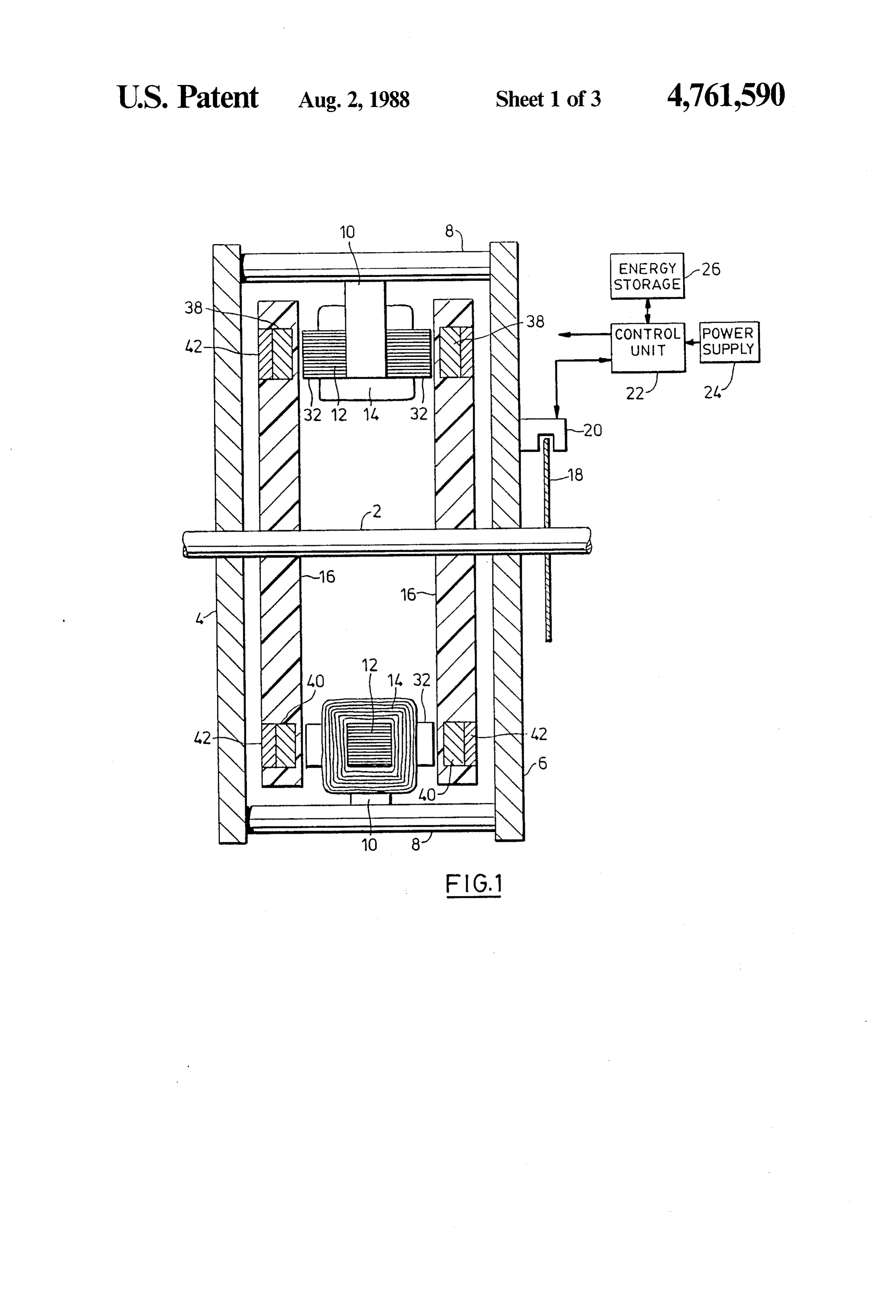
said stator exhibiting two angularly aligned axially Further details of the construction of the cores 12, spaced annular arrays of pole pieces at a predetermined coils 14 and rotor discs 16 will be described with addie pitch equal to the pitch of the rotor pole pieces, ar tional reference to FIG. 2. The cores 12 are of H config ranged so that the annular arrays of pole pieces of the 15 uration, with the cross bars 28 of the H's extending rotor discs can be aligned in close juxtaposition with the peripherally and the uprights 30 parallel to the axis of pole pieces of the annular arrays of the stator, the stator the motor towards the rotor discs. The coils 14a, 14b are comprising core members defining said pole pieces such bifilar wound on the cross bars 28, so that the uprights that angularly adjacent pairs of pole pieces in said pole provide pole pieces adjacent the rotors. Each upright 30 piece arrays of the stator are joined by said core mem provides two pole pieces 32 having the same polarity bers in an annularly arranged series of H configurations and a polarity opposite to that of the pole pieces 334 with cross bars in the H configurations extending pe provided by the other upright 30. The cores 12 are ripherally of the stator and stems of the H configura formed from a stack of soft magnetic H-shaped lamina tions extending parallel to the axis of the motor; electri tions 36.
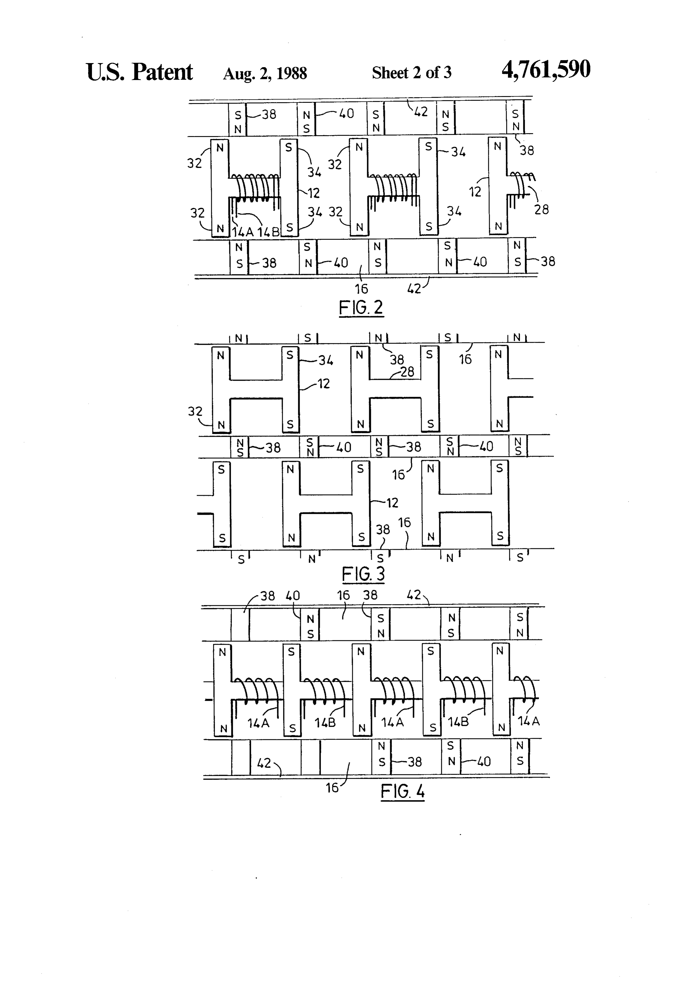
cally energizable windings on said cross bars of the H 25 In an alternative core construction shown in FIG. 4, configurations such that energization of said windings the cores 12 are connected into a ring by further cross polarizes pairs of pole pieces on stems at opposite ends bars 28, and the coils 14a and 14b are wound on alter of the cross bars of said H configurations, with the pole nate cross bars 28. In this case, the cores may be assem pieces on any one stem having like polarization and the bled from T-shaped laminations, and the arrangement pole pieces on neighbouring stems having opposite po- 30 may assist in maximizing the usage of available space by larization; electrical energy storage means external of the cores and windings.
said windings; and control means, connected between Referring to the arrangement of FIG. 2, a coil 14a or said windings, said electrical energy storage means and 14b when energized will magnetize its associated core connections to a direct current power supply, to control so as to provide north poles at one of the pairs of pole the direction and duration of energization of the wind- 35 pieces 32, 34 and south poles at the other pair. The FIG. ings with reference to the relative angular position of 3 embodiment will provide a similar effect in relation to the rotor and stator pole pieces such as to control angu the pole pieces adjacent an energized winding 14a or lar movement of the rotor. 14b.
Further features of the invention will become appar The rotor discs 16 are formed largely of non-mag ent from the following description with reference to the 40 netic material such as laminated fabric reinforced syn accompanying drawings. thetic plastic of suitable strength. Metals such as alumi
SHORT DESCRIPTION OF THE DRAWINGS
num may also be used, but care must then be taken to minimize losses due to eddy currents. High tenacity
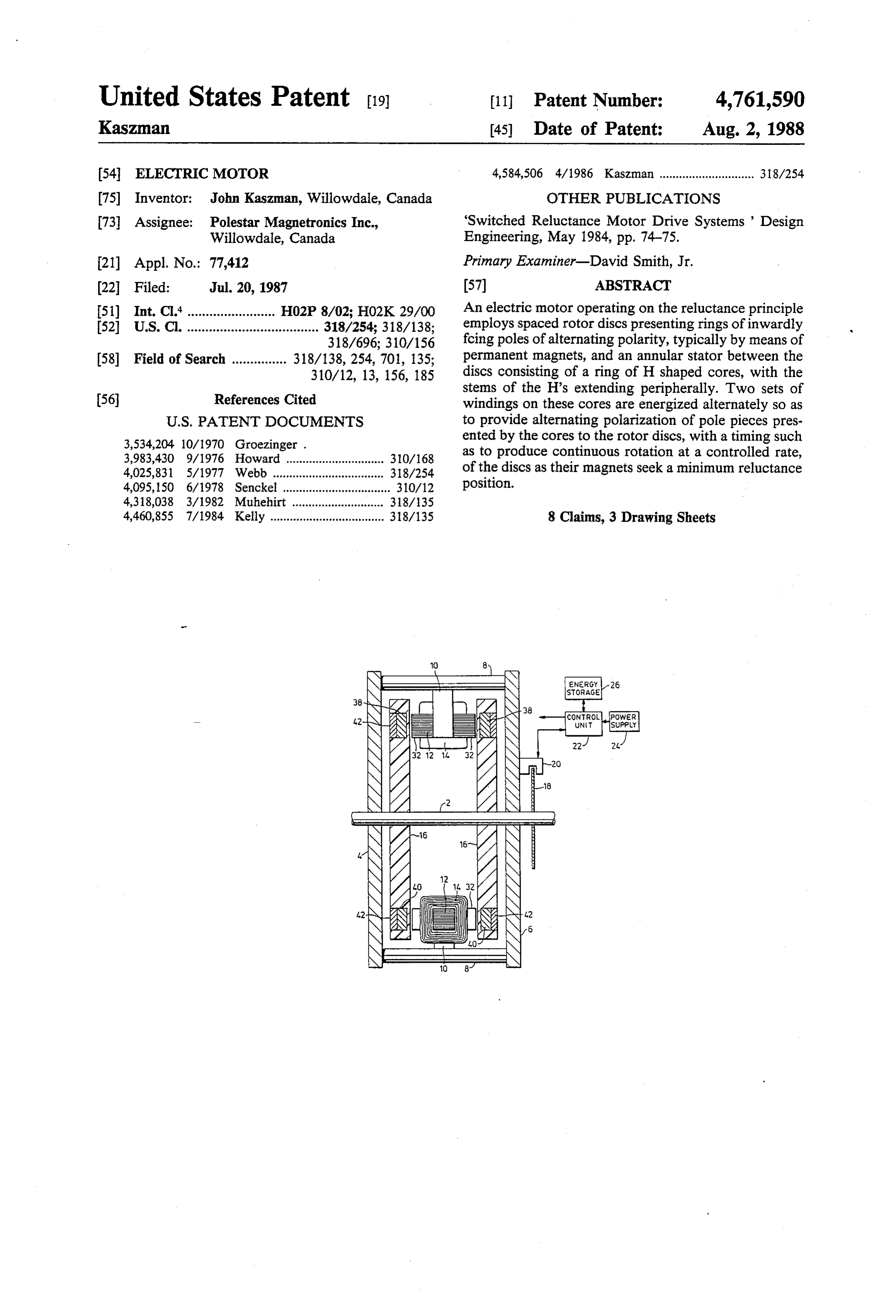
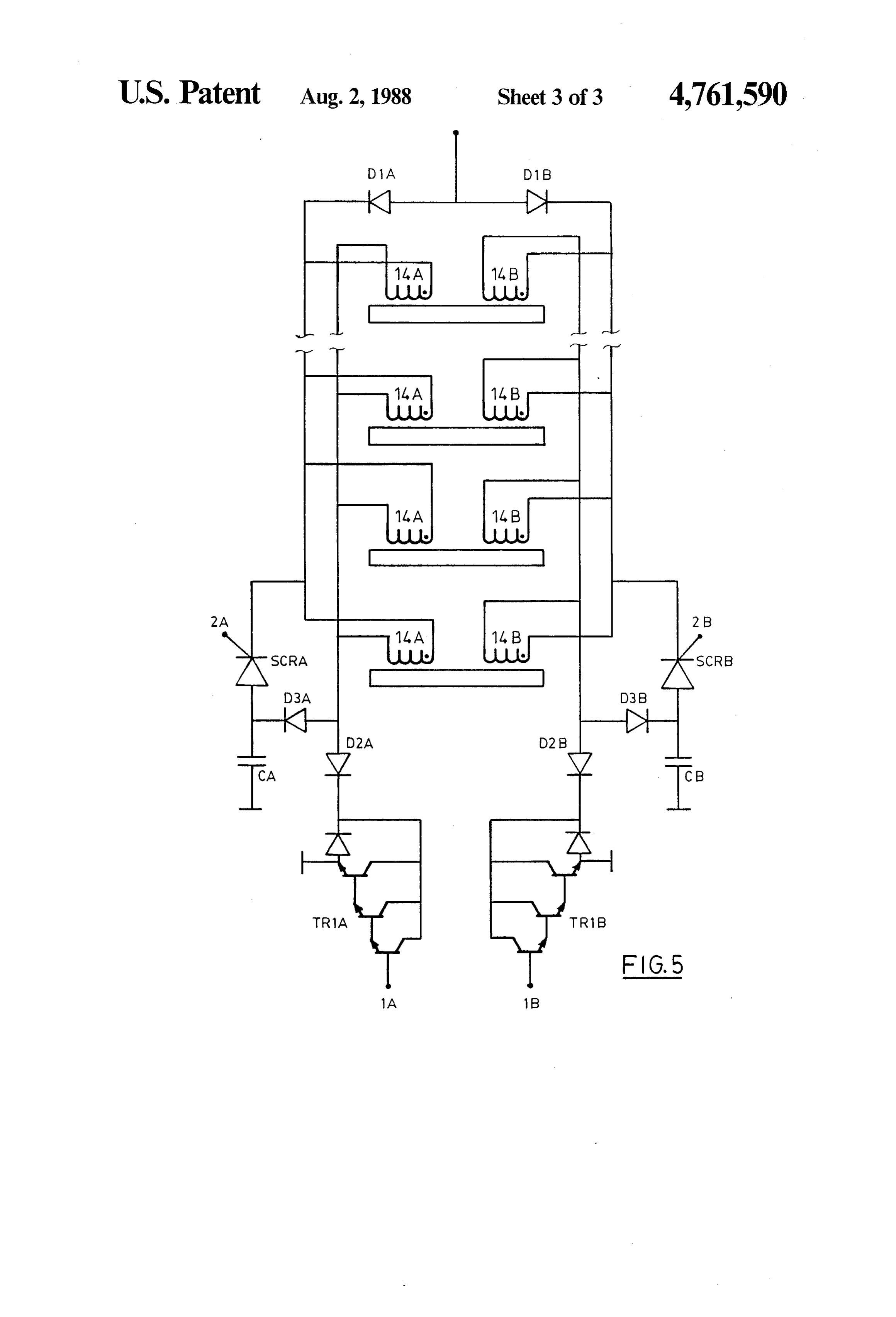
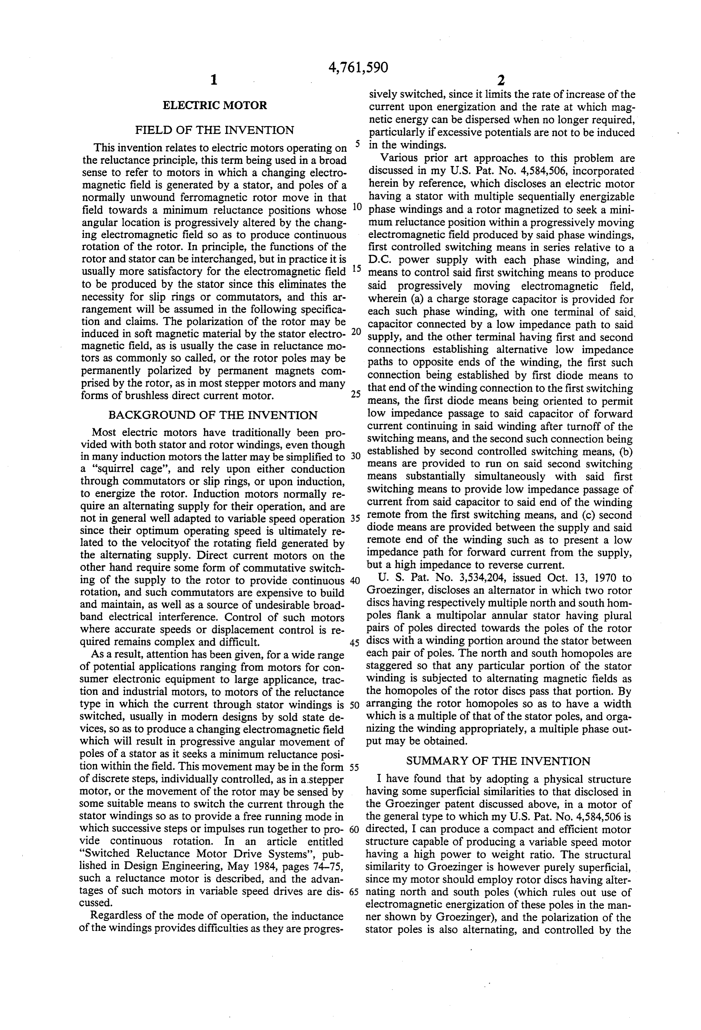
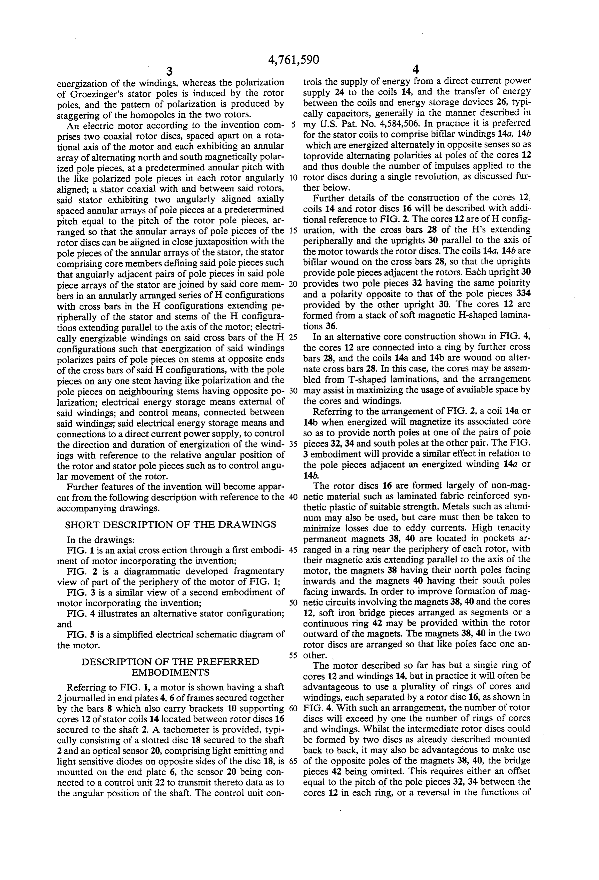
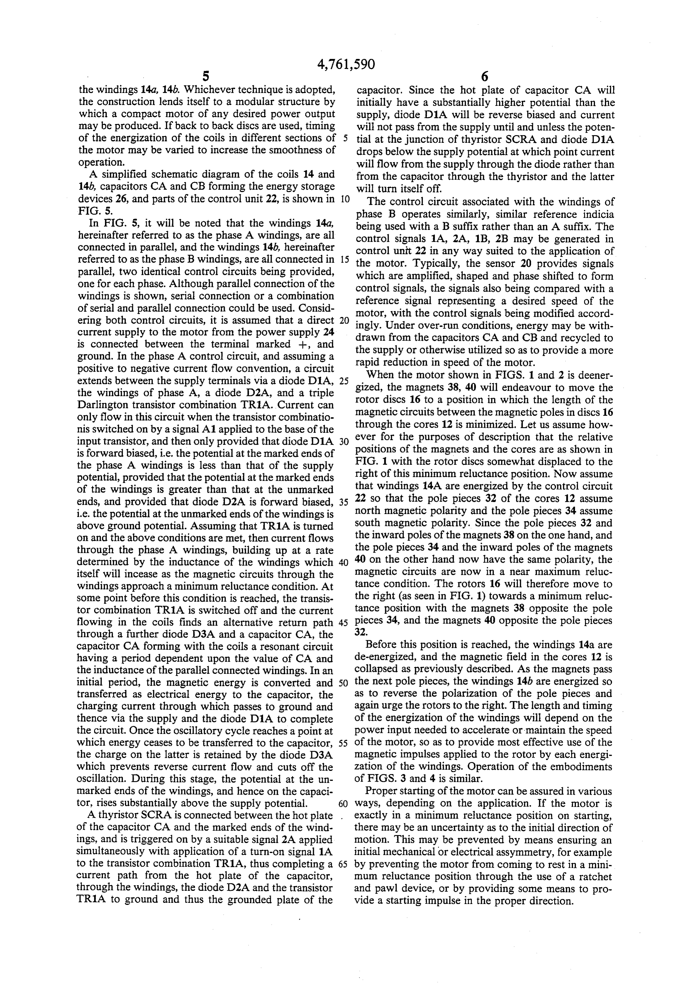
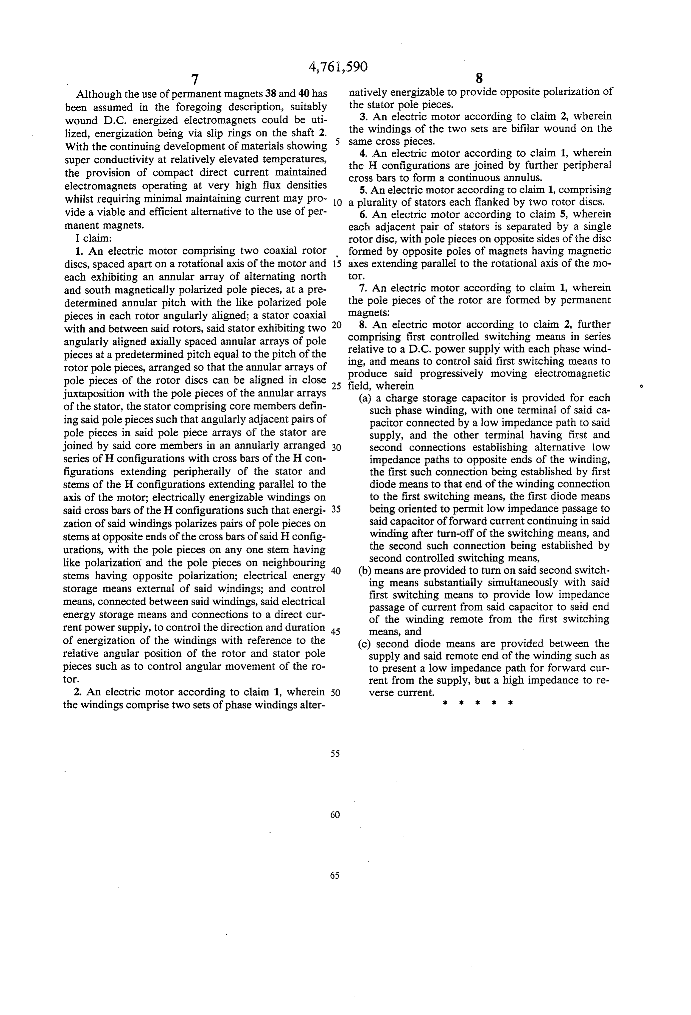
In the drawings: permanent magnets 38, 40 are located in pockets ar FIG. 1 is an axial cross ection through a first embodi- 45 ranged in a ring near the periphery of each rotor, with ment of motor incorporating the invention; their magnetic axis extending parallel to the axis of the FIG. 2 is a diagrammatic developed fragmentary motor, the magnets 38 having their north poles facing view of part of the periphery of the motor of FIG. 1; inwards and the magnets 40 having their south poles FIG. 3 is a similar view of a second embodiment of facing inwards. In order to improve formation of mag motor incorporating the invention; 50 netic circuits involving the magnets 38, 40 and the cores FIG. 4 illustrates an alternative stator configuration; 12, soft iron bridge pieces arranged as segments or a and continuous ring 42 may be provided within the rotor FIG. 5 is a simplified electrical schematic diagram of outward of the magnets. The magnets 38, 40 in the two the motor. rotor discs are arranged so that like poles face one an 55 other.
DESCRIPTION OF THE PREFERRED The motor described so far has but a single ring of EMBODIMENTS cores 12 and windings 14, but in practice it will often be Referring to FIG. 1, a motor is shown having a shaft advantageous to use a plurality of rings of cores and 2journalled in end plates 4, 6 of frames secured together windings, each separated by a rotor disc 16, as shown in by the bars 8 which also carry brackets 10 supporting 60 FIG. 4. With such an arrangement, the number of rotor cores 12 of stator coils 14 located between rotor discs 16 discs will exceed by one the number of rings of cores secured to the shaft 2. A tachometer is provided, typi and windings. Whilst the intermediate rotor discs could cally consisting of a slotted disc 18 secured to the shaft be formed by two discs as already described mounted 2 and an optical sensor 20, comprising light emitting and back to back, it may also be advantageous to make use light sensitive diodes on opposite sides of the disc 18, is 65 of the opposite poles of the magnets 38, 40, the bridge mounted on the end plate 6, the sensor 20 being con pieces 42 being omitted. This requires either an offset nected to a control unit 22 to transmit thereto data as to equal to the pitch of the pole pieces 32, 34 between the the angular position of the shaft. The control unit con cores 12 in each ring, or a reversal in the functions of
Page 7
the windings 14a, 14b. Whichever technique is adopted, capacitor. Since the hot plate of capacitor CA will the construction lends itself to a modular structure by initially have a substantially higher potential than the which a compact motor of any desired power output supply, diode D1A will be reverse biased and current may be produced. If back to back discs are used, timing will not pass from the supply until and unless the poten of the energization of the coils in different sections of 5 tial at the junction of thyristor SCRA and diode D1A the motor may be varied to increase the smoothness of drops below the supply potential at which point current operation. will flow from the supply through the diode rather than A simplified schematic diagram of the coils 14 and from the capacitor through the thyristor and the latter 14b, capacitors CA and CB forming the energy storage will turn itself off.
devices 26, and parts of the control unit 22, is shown in O The control circuit associated with the windings of FIG. 5. phase B operates similarly, similar reference indicia In FIG. 5, it will be noted that the windings 14a, being used with a B suffix rather than an A suffix. The hereinafter referred to as the phase A windings, are all control signals 1A, 2A, 1B, 2B may be generated in connected in parallel, and the windings 14b, hereinafter control unit 22 in any way suited to the application of referred to as the phase B windings, are all connected in 15 the motor. Typically, the sensor 20 provides signals parallel, two identical control circuits being provided, which are amplified, shaped and phase shifted to form one for each phase. Although parallel connection of the control signals, the signals also being compared with a windings is shown, serial connection or a combination reference signal representing a desired speed of the of serial and parallel connection could be used. Consid ering both control circuits, it is assumed that a direct 20 motor, ingly.
with the control signals being modified accord
Under over-run conditions, energy may be with current supply to the motor from the power supply 24 drawn from the capacitors CA and CB and recycled to is connected between the terminal marked --, and the supply or otherwise ground. In the phase A control circuit, and assuming a rapid reduction in speedutilized so as to provide a more of the motor.
positive to negative current flow convention, a circuit When the motor shown in FIGS. 1 and 2 is deener extends between the supply terminals via a diode D1A, 25 gized, the magnets 38, 40 will endeavour to move the the windings of phase A, a diode D2A, and a triple rotor discs 16 to a position in which the length of the Darlington transistor combination TR1A. Current can magnetic circuits only flow in this circuit when the transistor combinatio through the coresbetween the magnetic poles in discs 16 12 is minimized. Let us assume how nis switched on by a signal A1 applied to the base of the ever for the purposes of description that the relative input transistor, and then only provided that diode D1A 30 is forward biased, i.e. the potential at the marked ends of positions of the magnets and the cores are as shown in the phase A windings is less than that of the supply FIG. 1 with the rotor discs somewhat displaced to the potential, provided that the potential at the marked ends right of this minimum reluctance position. Now assume of the windings is greater than that at the unmarked that windings 14A are energized by the control circuit ends, and provided that diode D2A is forward biased, 35 22 so that the pole pieces 32 of the cores 12 assume i.e. the potential at the unmarked ends of the windings is north magnetic polarity and the pole pieces 34 assume above ground potential. Assuming that TR1A is turned south magnetic polarity. Since the pole pieces 32 and on and the above conditions are met, then current flows the inward poles of the magnets 38 on the one hand, and through the phase A windings, building up at a rate the pole pieces 34 and the inward poles of the magnets determined by the inductance of the windings which 40 40 on the other hand now have the same polarity, the itself will incease as the magnetic circuits through the magnetic circuits are now in a near maximum reluc windings approach a minimum reluctance condition. At tance condition. The rotors 16 will therefore move to some point before this condition is reached, the transis the right (as seen in FIG. 1) towards a minimum reluc tor combination TR1A is switched off and the current tance position with the magnets 38 opposite the pole flowing in the coils finds an alternative return path 45 pieces 34, and the magnets 40 opposite the pole pieces through a further diode D3A and a capacitor CA, the 32.
capacitor CA forming with the coils a resonant circuit Before this position is reached, the windings 14a are having a period dependent upon the value of CA and de-energized, and the magnetic field in the cores 12 is the inductance of the parallel connected windings. In an collapsed as previously described. As the magnets pass initial period, the magnetic energy is converted and 50 the next pole pieces, the windings 14b are energized so transferred as electrical energy to the capacitor, the as to reverse the polarization of the pole pieces and charging current through which passes to ground and again urge the rotors to the right. The length and timing thence via the supply and the diode D1A to complete of the energization of the windings will depend on the the circuit. Once the oscillatory cycle reaches a point at power input needed to accelerate or maintain the speed which energy ceases to be transferred to the capacitor, 55 of the motor, so as to provide most effective use of the the charge on the latter is retained by the diode D3A magnetic impulses applied to the rotor by each energi which prevents reverse current flow and cuts off the zation of the windings. Operation of the embodiments oscillation. During this stage, the potential at the un of FIGS. 3 and 4 is similar.
marked ends of the windings, and hence on the capaci Proper starting of the motor can be assured in various tor, rises substantially above the supply potential. 60 ways, depending on the application. If the motor is A thyristor SCRA is connected between the hot plate . exactly in a minimum reluctance position on starting, of the capacitor CA and the marked ends of the wind there may be an uncertainty as to the initial direction of ings, and is triggered on by a suitable signal 2A applied motion. This may be prevented by means ensuring an simultaneously with application of a turn-on signal 1A initial mechanical or electrical assymmetry, for example to the transistor combination TR1A, thus completing a 65 by preventing the motor from coming to rest in a mini current path from the hot plate of the capacitor, mum reluctance position through the use of a ratchet through the windings, the diode D2A and the transistor and pawl device, or by providing some means to pro TR1A to ground and thus the grounded plate of the vide a starting impulse in the proper direction.
Page 8
Although the use of permanent magnets 38 and 40 has natively energizable to provide opposite polarization of been assumed in the foregoing description, suitably the stator pole pieces.
wound D.C. energized electromagnets could be uti 3. An electric motor according to claim 2, wherein the windings of the two sets are bifilar wound on the lized, energization being via slip rings on the shaft 2. same
With the continuing development of materials showing cross pieces.
4. An electric motor according to claim 1, wherein super conductivity at relatively elevated temperatures, the H configurations are joined by further peripheral the provision of compact direct current maintained cross bars to form a continuous annulus. electromagnets operating at very high flux densities 5. An electric motor according to claim 1, comprising whilst requiring minimal maintaining current may pro 10 a plurality of stators each flanked by two rotor discs. vide a viable and efficient alternative to the use of per 6. An electric motor according to claim 5, wherein manent magnets. each adjacent pair of stators is separated by a single I claim: rotor disc, with pole pieces on opposite sides of the disc 1. An electric motor comprising two coaxial rotor formed by opposite poles of magnets having magnetic discs, spaced apart on a rotational axis of the motor and 15 axes extending parallel to the rotational axis of the mo each exhibiting an annular array of alternating north tOr.
and south magnetically polarized pole pieces, at a pre 7. An electric motor according to claim 1, wherein determined annular pitch with the like polarized pole the pole pieces of the rotor are formed by permanent pieces in each rotor angularly aligned; a stator coaxial 20 magnets:
with and between said rotors, said stator exhibiting two 8. An electric motor according to claim 2, further angularly aligned axially spaced annular arrays of pole comprising relative to a first controlled switching means in series
D.C. power supply with each phase wind pieces at a predetermined pitch equal to the pitch of the ing, and means to control said first Switching means to rotor pole pieces, arranged so that the annular arrays of produce said progressively moving electromagnetic pole pieces of the rotor discs can be aligned in close 25 field, wherein juxtaposition with the pole pieces of the annular arrays (a) a charge storage capacitor is provided for each of the stator, the stator comprising core members defin such phase winding, with one terminal of said ca ing said pole pieces such that angularly adjacent pairs of pacitor connected by a low impedance path to said pole pieces in said pole piece arrays of the stator are supply, and the other terminal having first and joined by said core members in an annularly arranged 30 second connections establishing alternative low series of H configurations with cross bars of the H con impedance paths to opposite ends of the winding, figurations extending peripherally of the stator and the first such connection being established by first stems of the H configurations extending parallel to the diode means to that end of the winding connection axis of the motor; electrically energizable windings on to the first switching means, the first diode means said crossbars of the H configurations such that energi 35 being oriented to permit low impedance passage to zation of said windings polarizes pairs of pole pieces on said capacitor of forward current continuing in said stems at opposite ends of the cross bars of said H config winding after turn-off of the switching means, and urations, with the pole pieces on any one stem having the second such connection being established by like polarization and the pole pieces on neighbouring 40 second controlled switching means, stems having opposite polarization; electrical energy (b) means are provided to turn on said second switch storage means external of said windings; and control ing means substantially simultaneously with said means, connected between said windings, said electrical first switching means to provide low impedance energy storage means and connections to a direct cur passage of current from said capacitor to said end of the winding remote from the first switching rent power supply, to control the direction and duration 45 means, and of energization of the windings with reference to the (c) second diode means are provided between the relative angular position of the rotor and stator pole supply and said remote end of the winding such as pieces such as to control angular movement of the ro to present a low impedance path for forward cur tor. rent from the supply, but a high impedance to re 2. An electric motor according to claim 1, wherein 50 verse current.
the windings comprise two sets of phase windings alter x: sk
Provenance
- Collection
- Cited prior art
- Original PDF
- patentimages.storage.googleapis.com →
- Filed
- 1987-07-20
- Pages
- 8
- Method
- pdftotext (the PDF's own text layer) + pdftoppm 300dpi page scans
- Source
- Google Patents bibliographic record
- Granted
- 1988-08-02
- Inventors
- John Kaszman; Polestar Magnetronics Inc
- Transcribed from
- patentimages.storage.googleapis.com →