patent · US1699732
Of san francisco
22 January 1929
Page 1
Drawing sheet — no readable text.
Page 2
Drawing sheet — no readable text.
Page 3
Patented Jan. 22, 1929. 1,699,732
UNITED STATES PATENT OFFICE.
CECIL. H. BALMAT, OF SAN FRANCISCO, CALIFORNIA, ASSIGNOR, BY MESNE ASSIGN. MENTS, TO STANDARD OIL COMPANY OF CALIFORNIA, OF SAN FRANCIsco, CALI.
FORNIA, A CORPORATION OF DELAWARE. .. .. . . ".
FURNACE.
Application filed June. 2, 1925. Serial No. 34,364.
This invention relates to a furnace for has been given to the proper shape and de 55 burning fuel oils, especially heavy fuel oils, sign of the furnace firebox and its relation and while the furnace may be adapted for to the burner.
other purposes, it is particularly intended The general object of this invention is to 5 toIn be useful as a domestic heating furnage. produce a furnace of simple construction in order to burn heavy fuel oil satisfactorily which the requisite temperature conditions 60 it is necessary to effect a suitable atomization are always maintained, even for the smallest of the fuel, to provide the correct quantity fires, and operating in such a way that the of air, and to maintain the proper tempera gases during combustion pass through a rela O ture during combustion. The burners which tively long path; also to provide a con are used in industrial plants for burning struction in which the flame or gas during 65 heavy oils are usually either of a type in combustion is caused to reverberate within which steam, or sometimes air, under high the firebox, at the same time providing means pressure is utilized to atomize the oil; or, of for protecting the burner from direct im 15 a type in which the oil is broken up by pingement of the reverberating flame; also to Imechanical means, either by being forced to provide means for producing a regenerating O issue from a small orifice or from the pe effect within the firebox, by directing the riphery of a rapidly revolving cup. In do reverberated flame along the same path as mestic installations, steam under high pres the flame issuing from the burner; also to 20 sure is not available; neither is compressed provide means for confining the flame more air, and furthermore, burners using these or less to the immediate vicinity of the fire 75 means for atomization are noisy in opera box; also to provide a furnace of relatively tion and require exact control, preferably by Small volume constructed entirely of refrac an expert. Burners using mechanical means tory material, which becomes highly heated for effecting the pulverization of the fuel and radiates or throws back a large amount are, in general, not very flexible under do of heat to the fire; and by this construction SO mestic conditions--that is, they have poor to permit the use of relatively simple means ability to change from a small to a large fire for atomization, or to increase materially, the efficiently. Furthermore, they require con efficiency and flexibility of burners utilizing RO siderable cleaning. . . Those burners which more complicated means.
utilize pressure alone for the atomization of A further object of the invention is to pro 85 the oil require high pressure pumps and in vide a construction in which the fuel oil is Small sizes, such as would be suitable for sufficiently heated to enable it to flow freely domestic use, the orifices are necessarily so to the burner tip, and to assist its atomiza Small as to become very easily stopped up. tion, but in which the fuel is sufficiently pro One of the difficulties in burning oil in a tected from the furnace heat to prevent its 90 domestic furnace lies in the fact that the volatilization before it reaches the tip of the shape and proportions of the furnace, or burner. .. . . . .. dinarily available are such as to require a Further objects of the invention will ap 4) very short length of flame, that is, extremely pear hereinafter.
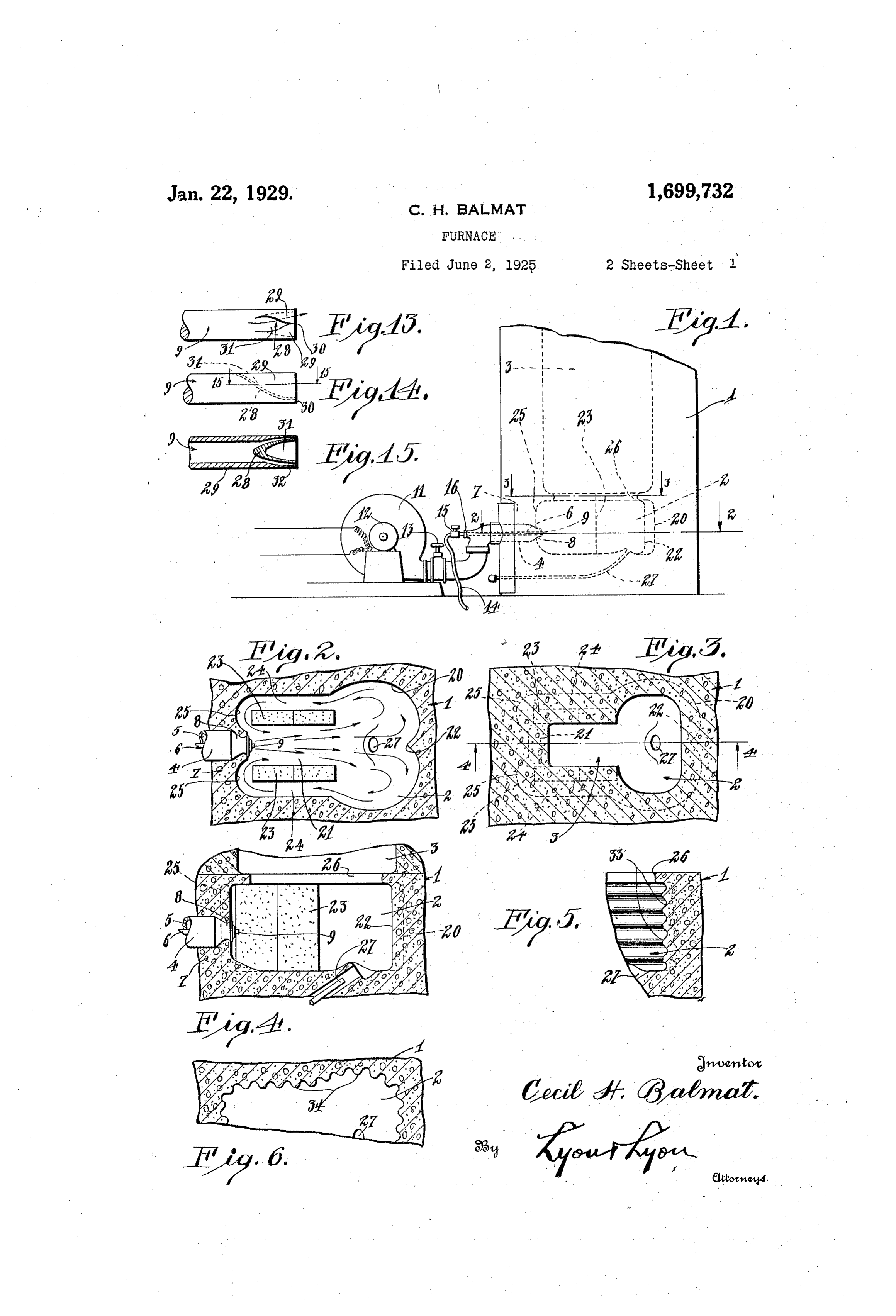
rapid combustion; moreover, the usual full The invention consists in the novel parts 95 nace will not hold the heat at low burning and combination of parts to be described rates sufficiently to effect proper combustion. hereinafter, all of which contribute to pro In order to burn heavy fuel oils successfully duce an efficient furnace. in the usual domestic furnace, therefore, it A preferred embodiment of the invention is necessary to effect the most thorough is described in the following specification, 100 atomization of the fuel in order to bring the while the broad scope of the invention is flame length into the practical limits lim pointed out in the appended claims. posed by the space available. As just In the drawings: . . . .. . . O pointed out, this thorough atomization - Fig. 1 is a diagrammatic view showing in necessitates the use of complicated means, side elevation a furnace embodying my in 05 and, in general, is very difficult to effect in vention, the upper portion of the furnace domestic installations. These difficulties ob being broken away.
tain primarily because little or no attention Fig. 2 is a horizontal section through the
Page 4
fire box, taken about In order to accomplish this, I provide a on the line 2-2 of burner
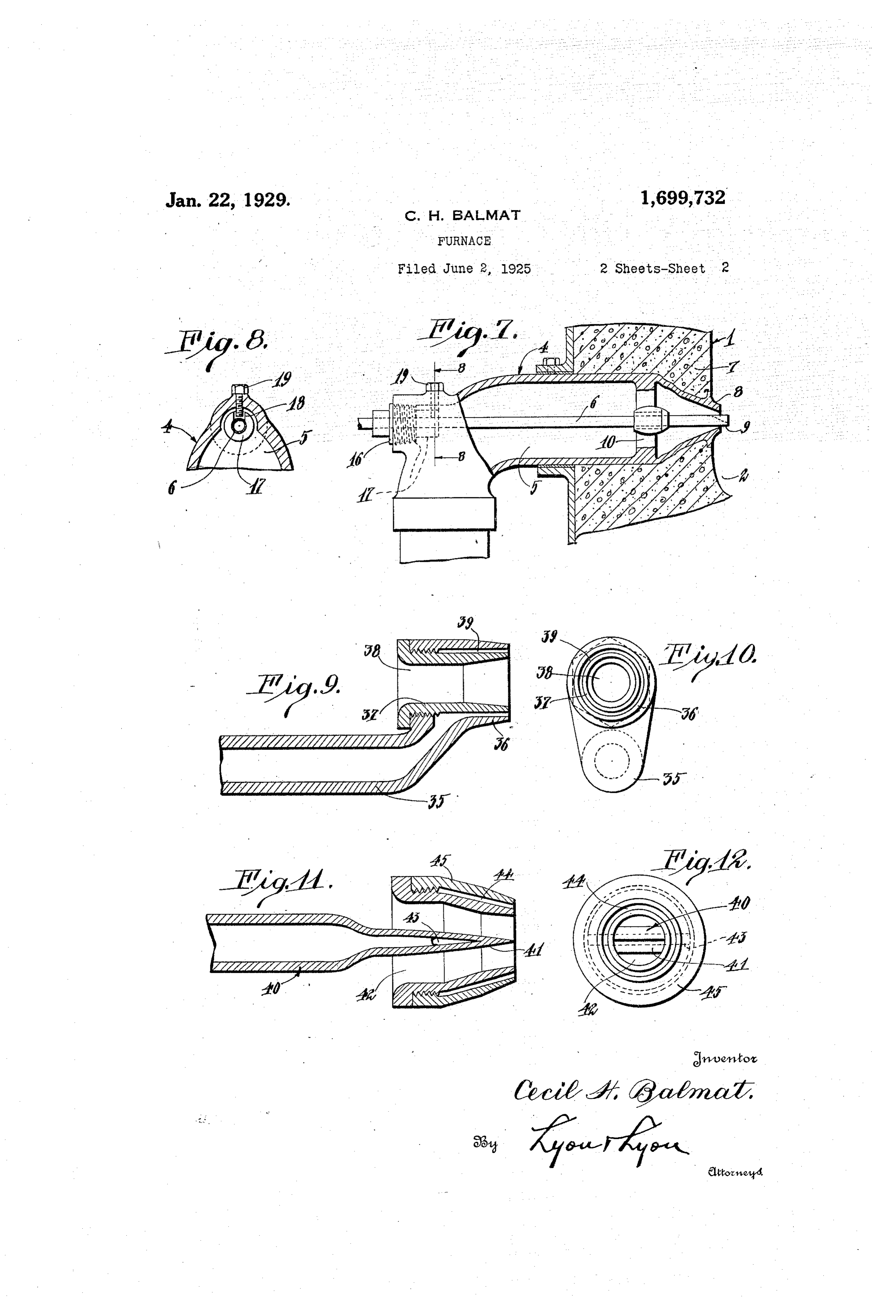
Fig. 1. - 4 which operates as an air duct or Fig. 3 is a cross section taken through the air nozzle 5. This nozzle 5 is of relatively furnace above the fire box on the line 3-3 large diameter and carries within it a fuel 70 of Fig. 1: . . . . . . pipe 6 which in the present instance is con Fig. 4 is a vertical section taken through structed to carry a relatively heavy oil fuel. the fire box on the line 4-4 of Fig. 3. The oil pipe 6 is preferably located centrally Fig. 5 is a vertical section at the side of in the air nozzle so that it is insulated by the fire box wall and showing a modified the air blast from the temperature in the () embodiment for the face of this wall to in fire box wall 7-in which the burner 4 is crease the conduction of heat into the fur mounted; this burner is constructed so that nace wall. although sufficient heat reaches the pipe to Fig. 6 is a horizontal section through a. enable the oil to flow freely in the coldest portion of the fire box wall and showing weather, at the same time it is sufficiently another embodiment of the idea disclosed in insulated due to the construction of the SO Fig. 5. - burner that the oil passing through the pipe Fig. 7 is a vertical section through the wall will not become volatilized. The air noz of the fire box and showing a portion of the zle 5 preferably has a tapered or conical tip burner in section, the rest of the burner 8, and the tip 9 of the fuel pipe preferably 85 20 being shown in elevation and the connec projects a fraction of an inch through the tion to it broken away. This view is upon orifice of the air nozzle (see Fig. 7). The an enlarged scale. forward end of the oil pipe may be sup Fig. 8 is a vertical section taken on the line. ported in a cross bar 10 which passes dia 8-8 of Fig. 7 illustrating details of the lock metrically across the air nozzle. The pipe 25 ing means for holding the fuel pipe in any 6, however, is adjustable through this arm or 90 adjusted position. bar 10. The air blast is preferably fur Fig. 9 is a longitudinal section illustrating nished by a fan or blower 11 which may he a modified embodiment of the burner nozzle. driven by an electric motor 12. The air is ; Fig. 10 is a front elevation of the burner preferably at a relatively low pressure. 30 shown in Fig. 9. Any suitable means may be employed for 9. Fig. 11 is a longitudinal section showing controlling the flow of the air blast to the another embodiment of the burner. burner, for example, a valve 13 may be pro Fig. 12 is a front elevation of the burner vided which in the present instance is lo shown in Fig.11. cated between the blower and the burner. Fig. 13 is a plan of the tip of the fuel By closing this valve more or less, the pipe shown in Fig. 7. amount of air flowing to the burner may be Fig. 14 is a side elevation of the tip shown nicely regulated. This valve may be of any
Fig. 13.is a horizontal section through the desired type.
The fuel oil may be supplied through a 20 fuel pipe tip taken about on the line 15–15 flexible pipe 14 which admits the oil through of Fig. 14. a valve 15 at the back end of the fuel pipe The furnace 1 which is illustrated is of 6. At its outer end, the fuel pipe is carried the upright type, with a fire box 2 at its in a bushing 16 which is screwed into the lower end and a combustion chamber 3 back of the air nozzle and suitable means 45 above the fire box. In applying my inven may be provided for locking the fuel pipe 0 tion to a furnace of this type. I provide and bushing in any adjusted position. For means for admitting an air blast and fuel this purpose, the bushing 16 may have an at one side of the fire box, and I construct extension or neck 17 at its inner end with a the fire box in such a way as to effect a longitudinal groove 18 which may receive 5 50 reverberation of the flame or gases during a set-screw 19 (see Fig. 8). combustion in a substantially horizontal Referring again to the fire box 2, the Wall plane so that they are made to flow back to opposite to the burner is provided with the end of the fire box where the fuel and means, for example a ridge or abutment 22, air are admitted. I also provide means for extending in a vertical direction, which is . 55 protecting my burner from direct impinge located on the axis of the burner, and this ment of the flame. This reverberation of ridge operates to divide the gases during the gases during combustion is preferably combustion, or the flame, into two currents, accomplished in such a way as to divide the as indicated by the arrows in Fig. 2; in other flame or gases into two currents which return words, the inner end of the fire box is con (30 to the front of the fire box along the face structed with a grooved face 20 at each side of the fire box Wall. The fire box is also which guides the flame back toward the front provided with regenerator means adjacent of the fire box.
the burner which also operates to assist in I provide suitable means to prevent this protecting the burner from impingement of flame from impinging on the burner, and 30 the flame. this function is performed by regenerator
Page 5
means in the form of a tunnel 21 between the slot becomes circular in form. One of two regenerator walls 23 disposed on op the sides thus is made into the inner wall or posite sides of the tunnel. Back of each wall tongue 28, and the other becomes the outer. 23 is a flue 24 through which the gases or wall and a continuation of the pipe. By 70 flames pass; at a point near the nozzle, and this operation, the points 29 of the flattened on each side of the nozzle, the wall of the fire tip are rolled together over the tongue so box is provided with curved guide faces 25 that they meet as at the point 30, in Fig. which bend the flame or gases during com 13. In this way, directly over the tongue bustion toward the back of the furnace. In 28, an air duct 31 is formed through which other words, this end of the fire box is shaped the air blast flows as indicated by the arrow so as to deflect the flame forwardly and over rowin Fig. 13; the effect is to provide a nar the burner so that it also assists the regener grooved throat 32 (see Fig. 15) into ator in protecting the burner from the flame. which the oil will pass by capillary attrac When the furnace is in operation, of tion. This enables the tip to operate effec th course the regenerator walls 23 become very tively although there may be a very small 80 highly heated, and if any drops of oil fail quantity of oil arriving at the tip. to be atomized sufficiently and fall upon the In order to increase the heat radiating faces of these walls 23, they will be imme surface of the furnace wall, I may provide the diately ignited or will be taken up again interior of the fire box with horizontal cor by the current of gases passing these faces. itrugations 33 (see Fig. 5) or I may provide 8 The furnace is preferably provided with with corrugations 34 (see Fig. 6). verti means operating to confine the gases during cally. The form of corrugations shown in combustion more or less to the fire boxes. Fig. 5 seems to be preferable, however, be Any suitable means may be provided for this cause it does not impede or produce eddy 25 purpose, but in the present instance Imerely currents in the flame as it passes along the on provide the inner face of the furnace waii side walls of the fire box; at the same time it would produce a very intimate contact be with a coping 26 which projects horizontally into the furnace chamber and divides the fire tween the flame and the fire box wall, en box from the combustion chamber 3 above it. ablings the wall to absorb a very consider 30 This coping extends further out into the fireable quantity of the heat in the gases or 5 flame.
box at the end of the fire box which is locat Other types of fuel pipe tips or nozzles ed near the burner, so that it extends over the regenerator walls 23 and assists inform are illustrated in Figs. 9 to 12. In the form ing the return flues 24. shown in Fig. 9, the end of the fuel duct In starting up a furnace with a heavy fuel or fuel pipe 35 is bent up and formed into 100 oil it is sometimes necessary to provide spe an annular nozzle 36 into which a bushing 37 may be screwed from the rear. This cial means for igniting the oil and warming bushing up the burner. This may be accomplished 37 carries an air duct 38. The if desired by throwing some oil-soaked waste bushing 37 is of slightly smaller diameter 05 40 into the furnace, or, if desired, a gas con than the nozzle 36, so that a narrow annular. nection 27 may be run into the back part space may, 39 is formed around the bushing which if it is small enough, exert capillary at of the furnace. If desired, the connection 27 may be used after starting the furnace for traction on the oil.
delivering an additional supply of air, or in Fig.11,type
In the of burner or oil pipe tip shown pipe 40 is drawn down into a Ilo other connections may be used at other tapeited endthe or spear 41 which passes into the points in the furnace for admitting addi tional air for combustion. center of an air nozzle 42 to which it is con The tip 9 may have any form or construc nected. A passage 43 leads from the in tion desired, and steam, air, mechanical, or terior of the spear into a conical annularis 50 other means may be used to effect the desired space 44 around the nozzle 42, this space atomization of the fuel; I prefer, however, formednozzle by screwing on the nozzle 42 an to utilize a low pressure air blast for atomiz. outer 45 of conical form. ing the fuel and to construct the tip so that It is evident that in the operation of this furnace, the construction of the fire box is 20
the features illustrated in Figs. 13 to such tip is produced by swaging out as to guide the flame or gases during the end of the oil pipe to the shape of a fun the fire box.in At combustion a relatively long path within the same time, a regenera nel and then flattening it to a fan-shaped to effect is produced, though the burner is outline. Between the two sides a narrow slot is left, and this capillary space is kept protected from impingement of the flame. 60. intact during the remaining operations by The fire-box, of course, may be constructed 125 any suitable means, but most conveniently of fire clay, fire brick, or any other suitable by the insertion of a triangle of thin sheet refractory material. . . . . . ... .. -
metal, which is withdrawn when the work is theItinvention is understood that the embodiment of described herein is only one of finished. The tip is then rolled about a
(B5 longitudinal axis so that, looking on the end, the many embodiments this invention may 130
Page 6
take, and I do not wish to be limited in the and having a return flute on the outer side of practice of the invention, nor in the claims, each regenerator Wall, means for admitting to the particular embodiment set forth. an air blast at the nozzle so as to direct the What I claim is:- fuel between the regenerator walls, said fire 1. In a furnace for burning heavy oils, box having means for effecting a reverbera the combination of a fire-box, an air-duct tion of the gases during combustion rear mounted in the fire-box wall, a fuel-oil pipe wardly through the said flues and thereafter extending longitudinally through the air forwardly between the regenerator walls. clict and projecting at its inner end beyond 5. A fire box having means for effecting the end of the air-duct, said air-duct being of leverberation of the flame in a substantially relatively large diameter whereby the fuel horizontal plane, and having corrugations pipe within the same is insulated from the On the inner face of the wall in contact with high temperature of the fire-box Wall, and the fiane.
regenerator means located in the fire-box ad 6. A furnace for burning heavy fuel oils jacent the burner, said fire-box having means having a burner constructed to operate with 8 for effecting a reverberation of the gases dur a low pressure air blast and operating to ing combustion past the regenerator means. atomize oil with the air blast and direct the 2. In a furnace for burning heavy oils, the same across the fire-box of the furnace, a combination of a fire-box, an air-duct mount combustion chamber above the fire-box, said 85 ed in the fire-box wall, a fuel-oil pipe extend fire-box having a ridge in its wall opposite ing longitudinally through the air-duct and the burner to divide the burning gases and projecting at its inner end beyond the end effect a reverberation thereof by directing of the air-duct, said air-dict being of rela the same in two currents in the same hori tively large diameter whereby the fuel pipe Zontal plane and passing along the face of 90 within the same is insulated from the high the side walls of the furnace back toward temperature of the fire-box wall, and regen the burner, said fire-box having means pro erator means located in the fire-box adjacent jecting in from the Wall above the currents the burner, said fire-box having means for of gases operating to confine the same within effecting a reverberation of the gases during the fire-box, a regenerator device at each side combustion past the regenerator means, said of the nozzle in a position to become highly fuel pipe being disposed substantially cen heated by the flame from the burner, and trally within the air duct, whereby the air covered tunnels on the outer sides of the blast surrounding the fuel pipe operates to regenerator devices receiving the said cur cool, and insulate the same from the high rents of gases passing along the walls of the OO temperature of the fire-box wall. fire-box, and means in the fire-box adjacent 3. A furnace for burning heavy fuel oils the burner for deflecting the currents pass having a burner constructed to operate with ing through the tunnels forwardly past the a low pressure air blast, and operating to burner and between the regenerator devices, atomize oil with the air blast and direct the 7. A furnace for burning heavy fuel oils 40 same across the fire-box of the furnace, a having a burner constructed to operate with combustion chamber above the fire-box, said a low pressure air-blast and operating to fire-box having a ridge in its wall opposite atomize oil with the air-blast and direct the the burner to divide the burning gases and Same across the fire-box of the furnace, a effect a reverberation thereof by directing Combustion chamber above the fire-box said O 4. the same in currents passing along the face fire-box having a regenerator Wall on each of the side walls of the furnace back to side of the burner, disposed in a substantially ward the burner, said fire-box having vertical plane and extending longitudinally means projecting in from the wall above With the axis of the burner, said fire-box the current of gases operating to confine having covered flues on the outer sides of 5 the same within the fire-box, a regenerator the regenerator walls forming covered tun device at each side of the nozzle in a posi nels for directing the flame back toward the tion to become highly heated by the flame forward wall of the fire-box, the forward from the burner, and covered tunnels on Wall of the fire-box having means on each the outer sides of the regenerator devices side of the burner for deflecting the currents 20 receiving the said currents of gases passing passing through the said files, past the along the Walls of the fire box, and means burner and between the regenerator walls in the fire-box adjacent the burner for de and toward the rear Wall of the furnace. flecting the currents passing through the 8. In a furnace for burning heavy fuel oils,
tunnels forwardly past the burner and be the combination of a burner constructed to 25 tween the regenei'ator devices. operate with a low pressure air-blast and 4. In a furnace, the combination of a fire operating to atomize oil with the air-blast box and a combustion chamber above the and direct it across the fire-box of the fire-box, a nozzle for admitting the fuel, a furnace, a combustion chamber above the regenerator adjacent the nozzle with a re fire-box, the back wall of the fire-box op
generator. Wall on each side of the nozzle erating to divide the current of flame from 30
Page 7
the burner into two currents in the same a tunnel for guiding its corresponding cur 0. horizontal plane passing toward the front rent of flame back to the front wall of the wall of the furnace along the vertical faces fire-box, the said front wall of the fire-box of its side walls, a pair of regenerator walls having means for deflecting the two rever 5 disposed in a substantially vertical plane berated currents of flame past the burner one on each side of the burner and extending and between the said regenerator Walls. 5 longitudinally with the axis of the burner, Signed at San Francisco, Calif. this 21st said fire-box having a covered flue on the day of May, 1925.
outer side of each regenerator wall forming CECIL. H. BALMAT.

Provenance
- Collection
- Cited prior art
- Original PDF
- patentimages.storage.googleapis.com →
- Pages
- 7
- Method
- pdftotext (the PDF's own text layer) + pdftoppm 300dpi page scans
- Source
- Google Patents bibliographic record
- Granted
- 1929-01-22
- Transcribed from
- patentimages.storage.googleapis.com →