patent · US5888361
Apparatus for producing hydrogen and oxygen
30 March 1999
Page 1 — bibliographic record
United States Patent (19) 11 Patent Number: 5,888,361 Hirai et al. (45) Date of Patent: Mar. 30, 1999 54 APPARATUS FOR PRODUCING HYDROGEN 5,632,870 5/1997 KucheroV ............................ 204/262 X AND OXYGEN 5,690,797 11/1997 Harada et al. ...................... 204/239 X
75 Inventors: Kiyoshi Hirai; Shinichi Yasui, both of FOREIGN PATENT DOCUMENTS Kakogawa; Hiroko Kobayashi, Kobe; 2051859 3/1992 Canada ............................ C25B 1/12 Teruyuki Morioka, Kakogawa; Akiko O 478 980A1 4/1992 European Pat. Off. .......... C25B 1/12 Miyake, Kobe; Hiroyuki Harada, 573O88 6/1924 France.
Tokyo, all of Japan 2410.058 6/1979 France ............................. C25B 9/00
73 Assignee: Shinko Pantec Co., Ltd., Hyogo, Japan WO 91/07525 5/1991 WIPO .............................. C25B 9/00
21 Appl. No.: 850,280 Primary Examiner Donald R. Valentine Attorney, Agent, or Firm Marshall, O'Toole, Gerstein, 22 Filed: May 5, 1997 Murray & Borun 30 Foreign Application Priority Data 57 ABSTRACT May 8, 1996 JP Japan .................................... 8-113458 A Simply configured cooling mechanism for an apparatus for May 27, 1996 JP Japan ... producing hydrogen and oxygen is disclosed. The configu 51) Int. Cl. ............................... C25B 9/00; C25B 15/02 ration makes it possible to freely Select the type of heat 52 U.S. Cl. .......................... 204/262; 204/266; 204/274; eXchanger, without any restrictions, in order to improve 204/278; 118/429 cooling efficiency. In particular, a heat eXchanger for cooling 58 Field of Search ..................................... 204/256-258, deionized water in a deionized water tank, which contains an 204/241, 260, 262, 239; 118/429 electrolytic cell, is installed outside the tank. An inlet to the heat eXchanger is connected to a deionized water flow outlet 56) References Cited from the tank that is below the level of the deionized water the tank by a pipe, and an outlet from the heat eXchanger to
4,891,116 1/1990 Stritzke ............................... x positioned in the tank below the deionized water flow outlet. 5,082.544 1/1992 Willey et al. ... ... 204/270 5,401,371 3/1995 Oshima et al. ......................... 204/258 13 Claims, 12 Drawing Sheets
NSNSS -sz 2
M \, NNS SNN 222
NN N 22 4.
NR NN 22 -N-J NNS 22
SS %2
7b %
9b. 2
Page 2
Drawing sheet — no readable text.
Page 3
Drawing sheet — no readable text.
Page 4
Drawing sheet — no readable text.
Page 5
Drawing sheet — no readable text.
Page 6
Drawing sheet — no readable text.

Page 7
Drawing sheet — no readable text.
Page 8
Drawing sheet — no readable text.
Page 9
Drawing sheet — no readable text.
Page 10
Drawing sheet — no readable text.
Page 11
Drawing sheet — no readable text.
Page 12
Drawing sheet — no readable text.
Page 13
Drawing sheet — no readable text.
Page 14
APPARATUS FOR PRODUCING HYDROGEN Normally, the temperature of the deionized water in the AND OXYGEN above-mentioned deionized water tank rises due to heat FIELD OF THE INVENTION generation at the time of electrolysis. This is not desirable The present invention relates to an apparatus for produc from the Viewpoint of preventing thermal degradation of the ing hydrogen and oxygen of high purity (hereinafter referred parts, and the like, of electrolytic cell 52. Moreover, a rise in to as “HHOG”). In particular, the present invention relates to temperature of the deionized water results in an increase in an HHOG which electrolyzes deionized water to produce water vapor in deionized water tank 53, and in turn, in an hydrogen gas and oxygen gas of high purity, and is capable increase in the moisture content of the generated oxygen gas. of cooling deionized water in a tank that contains an 1O AS a result, the dehumidification load increases. Moreover, electrolytic cell. a high temperature of deionized water tank 53 is not desir
DISCLOSURE OF THE RELATED ART
able for the workers working in the vicinity of the apparatus.
Hence, according to the prior art, a heat eXchanger 59 for
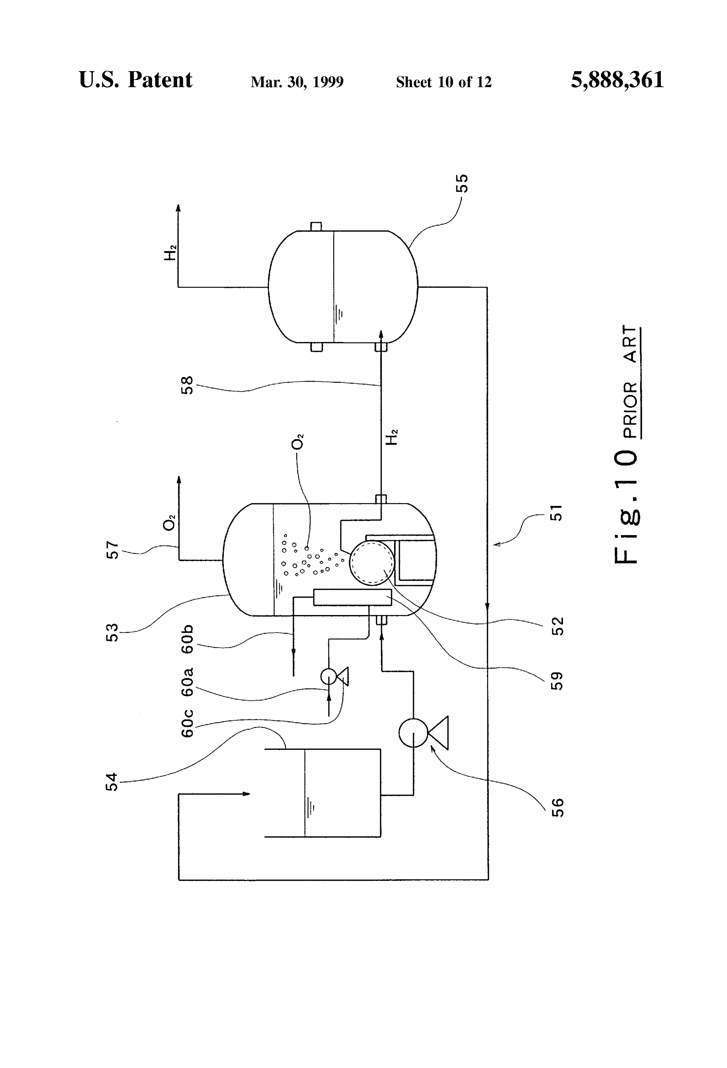
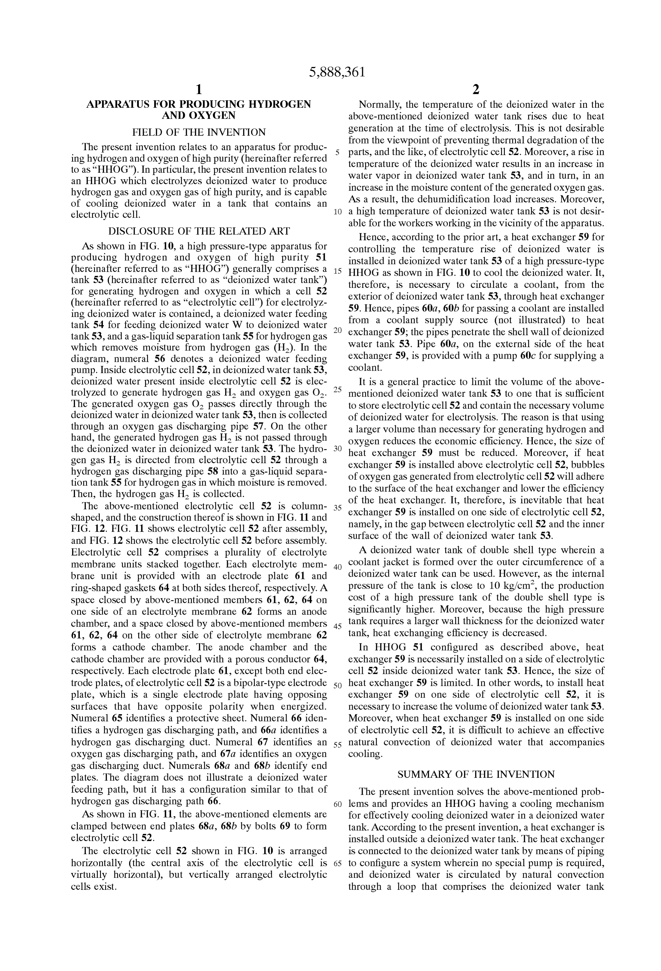
AS shown in FIG. 10, a high preSSure-type apparatus for controlling the temperature rise of deionized water is producing hydrogen and oxygen of high purity 51 installed in deionized water tank 53 of a high preSSure-type (hereinafter referred to as “HHOG”) generally comprises a 15 HHOG as shown in FIG. 10 to cool the deionized water. It, tank 53 (hereinafter referred to as “deionized water tank”) therefore, is necessary to circulate a coolant, from the for generating hydrogen and oxygen in which a cell 52 (hereinafter referred to as “electrolytic cell”) for electrolyz exterior
of deionized water tank 53, through heat eXchanger
Hence, pipes 60a, 60b for passing a coolant are installed ing deionized water is contained, a deionized water feeding from a coolant Supply Source (not illustrated) to heat tank 54 for feeding deionized water W to deionized water exchanger 59; the pipes penetrate the shell wall of deionized tank 53, and a gas-liquid Separation tank.55 for hydrogen gas which removes moisture from hydrogen gas (H2). In the water tank 53. Pipe 60a, on the external side of the heat diagram, numeral 56 denotes a deionized water feeding coolant. exchanger 59, is provided with a pump 60c for Supplying a pump. Inside electrolytic cell 52, in deionized water tank 53, deionized water present inside electrolytic cell 52 is elec 25 It is a general practice to limit the Volume of the above trolyzed to generate hydrogen gas H2 and OXygen gas O2. mentioned deionized water tank 53 to one that is Sufficient The generated oxygen gas O2 passes directly through the to Store electrolytic cell 52 and contain the necessary volume deionized water in deionized water tank 53, then is collected of deionized water for electrolysis. The reason is that using through an oxygen gas discharging pipe 57. On the other a larger Volume than necessary for generating hydrogen and hand, the generated hydrogen gas H2 is not passed through oxygen reduces the economic efficiency. Hence, the size of the deionized water in deionized water tank 53. The hydro heat exchanger 59 must be reduced. Moreover, if heat gen gas H2 is directed from electrolytic cell 52 through a exchanger 59 is installed above electrolytic cell 52, bubbles hydrogen gas discharging pipe 58 into a gas-liquid Separa of oxygen gas generated from electrolytic cell 52 will adhere tion tank 5.5 for hydrogen gas in which moisture is removed. to the Surface of the heat exchanger and lower the efficiency Then, the hydrogen gas H2 is collected. of the heat eXchanger. It, therefore, is inevitable that heat The above-mentioned electrolytic cell 52 is column 35 exchanger shaped, and the construction thereof is shown in FIG. 11 and namely, in 59 is installed on one side of electrolytic cell 52, FIG. 12. FIG. 11 shows electrolytic cell 52 after assembly, Surface of the gap the between electrolytic cell 52 and the inner wall of deionized water tank 53.
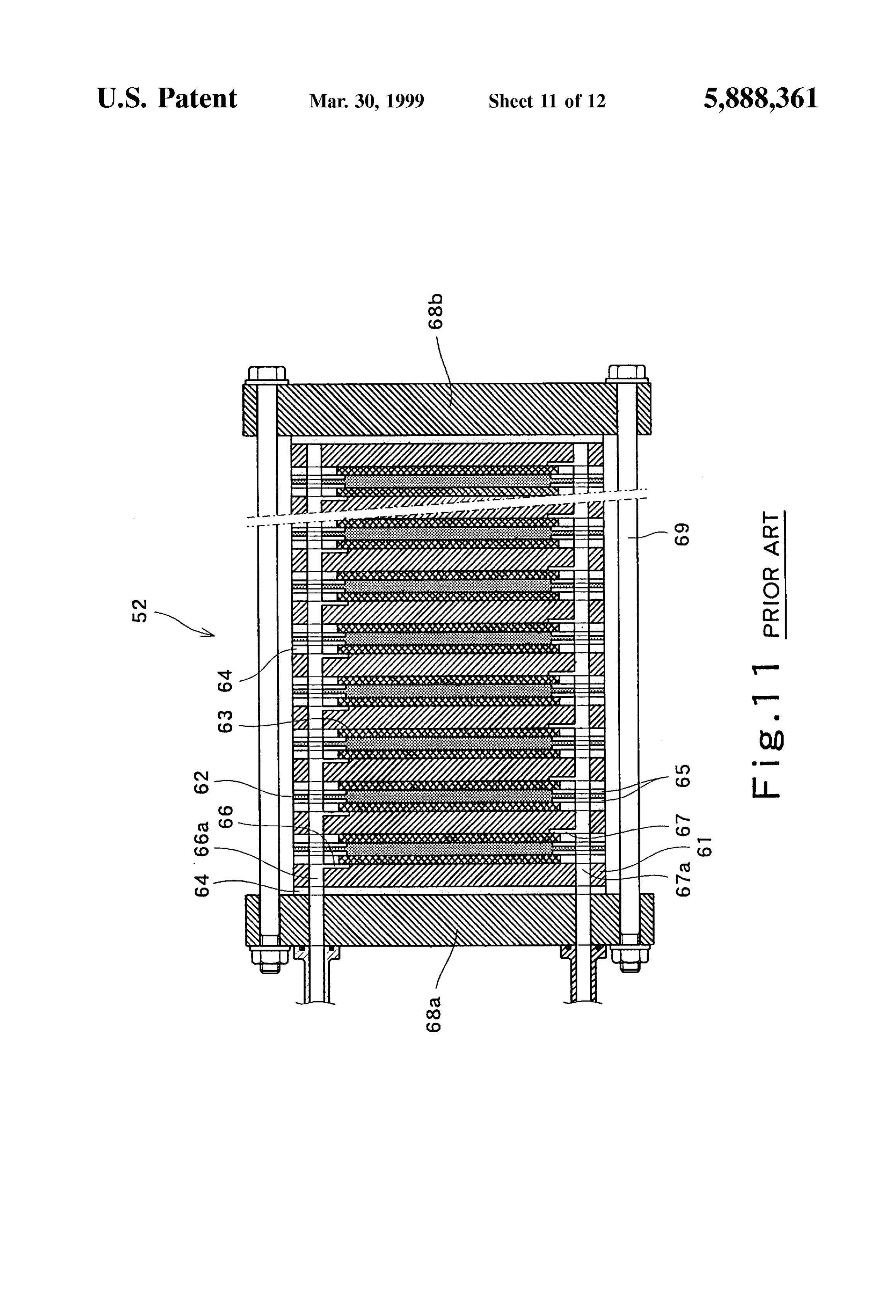
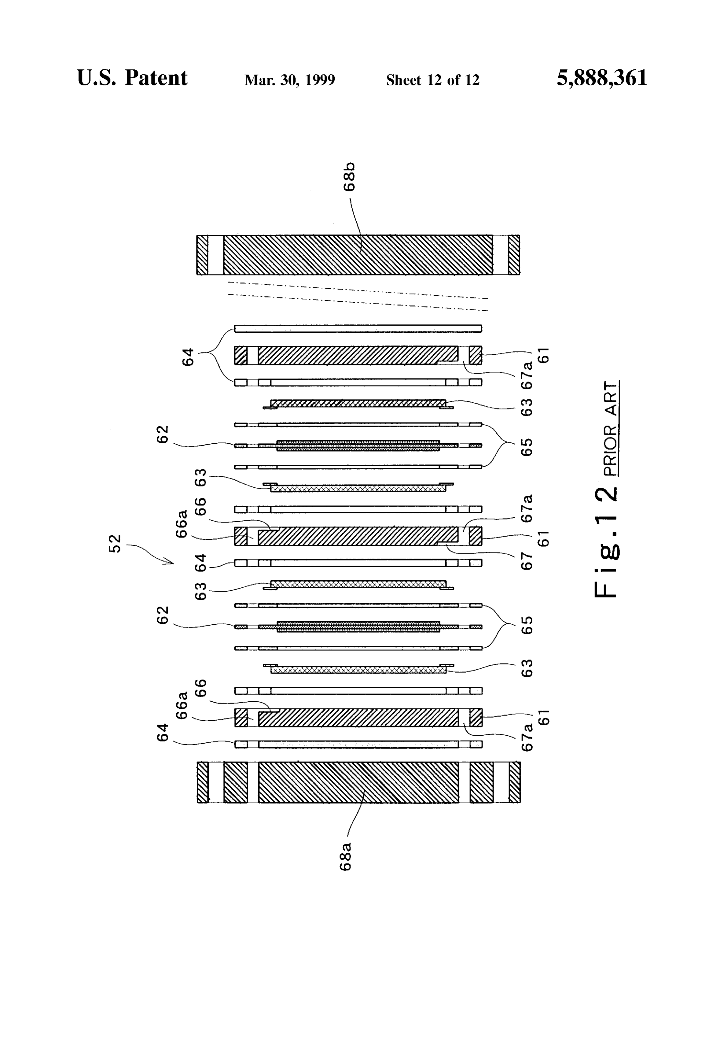
and FIG. 12 shows the electrolytic cell 52 before assembly.
Electrolytic cell 52 comprises a plurality of electrolyte A deionized water tank of double shell type wherein a membrane units Stacked together. Each electrolyte mem 40 coolant jacket is formed over the outer circumference of a brane unit is provided with an electrode plate 61 and deionized water tank can be used. However, as the internal ring-shaped gaskets 64 at both Sides thereof, respectively. A pressure of the tank is close to 10 kg/cm, the production space closed by above-mentioned members 61, 62, 64 on cost of a high pressure tank of the double shell type is one side of an electrolyte membrane 62 forms an anode Significantly higher. Moreover, because the high preSSure chamber, and a Space closed by above-mentioned members 45 tank requires a larger wall thickness for the deionized water 61, 62, 64 on the other side of electrolyte membrane 62 tank, heat eXchanging efficiency is decreased. forms a cathode chamber. The anode chamber and the In HHOG 51 configured as described above, heat cathode chamber are provided with a porous conductor 64, eXchanger 59 is necessarily installed on a Side of electrolytic respectively. Each electrode plate 61, except both end elec cell 52 inside deionized water tank 53. Hence, the size of trode plates, of electrolytic cell 52 is a bipolar-type electrode 50 heat exchanger 59 is limited. In other words, to install heat plate, which is a Single electrode plate having opposing exchanger 59 on one side of electrolytic cell 52, it is Surfaces that have opposite polarity when energized. necessary to increase the Volume of deionized water tank 53. Numeral 65 identifies a protective sheet. Numeral 66 iden Moreover, when heat exchanger 59 is installed on one side tifies a hydrogen gas discharging path, and 66a identifies a of electrolytic cell 52, it is difficult to achieve an effective hydrogen gas discharging duct. Numeral 67 identifies an 55 natural convection of deionized water that accompanies oxygen gas discharging path, and 67a identifies an oxygen cooling.
gas discharging duct. Numerals 68a and 68b identify end plates. The diagram does not illustrate a deionized water SUMMARY OF THE INVENTION feeding path, but it has a configuration Similar to that of The present invention solves the above-mentioned prob hydrogen gas discharging path 66. 60 lems and provides an HHOG having a cooling mechanism As shown in FIG. 11, the above-mentioned elements are for effectively cooling deionized water in a deionized water clamped between end plates 68a, 68b by bolts 69 to form tank. According to the present invention, a heat eXchanger is electrolytic cell 52. installed outside a deionized water tank. The heat eXchanger The electrolytic cell 52 shown in FIG. 10 is arranged is connected to the deionized water tank by means of piping horizontally (the central axis of the electrolytic cell is 65 to configure a System wherein no special pump is required, Virtually horizontal), but vertically arranged electrolytic and deionized water is circulated by natural convection cells exist. through a loop that comprises the deionized water tank
Page 15
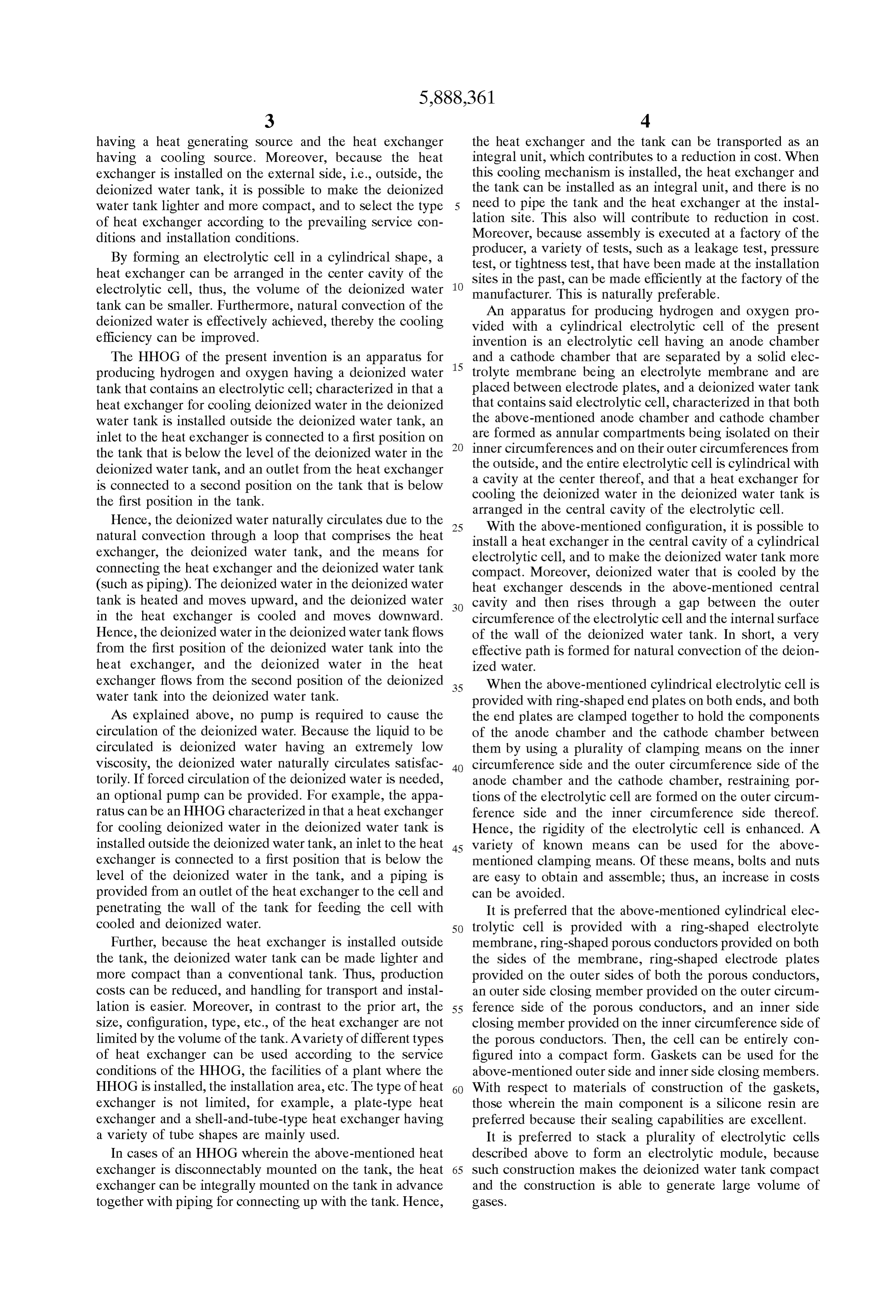
having a heat generating Source and the heat eXchanger the heat eXchanger and the tank can be transported as an having a cooling Source. Moreover, because the heat integral unit, which contributes to a reduction in cost. When eXchanger is installed on the external Side, i.e., outside, the this cooling mechanism is installed, the heat eXchanger and deionized water tank, it is possible to make the deionized the tank can be installed as an integral unit, and there is no water tank lighter and more compact, and to Select the type need to pipe the tank and the heat eXchanger at the instal of heat eXchanger according to the prevailing Service con lation site. This also will contribute to reduction in cost. ditions and installation conditions. Moreover, because assembly is executed at a factory of the By forming an electrolytic cell in a cylindrical shape, a producer, test, or a variety of tests, Such as a leakage test, preSSure tightness test, that have been made at the installation heat eXchanger can be arranged in the center cavity of the Sites in the past, can be made efficiently at the factory of the electrolytic cell, thus, the Volume of the deionized water manufacturer. This is naturally preferable. tank can be Smaller. Furthermore, natural convection of the An apparatus for producing hydrogen and oxygen pro deionized water is effectively achieved, thereby the cooling vided with a cylindrical electrolytic cell of the present efficiency can be improved. invention is an electrolytic cell having an anode chamber The HHOG of the present invention is an apparatus for 15 and a cathode chamber that are separated by a Solid elec producing hydrogen and oxygen having a deionized water trolyte membrane being an electrolyte membrane and are tank that contains an electrolytic cell; characterized in that a placed between electrode plates, and a deionized water tank heat eXchanger for cooling deionized water in the deionized that contains Said electrolytic cell, characterized in that both water tank is installed outside the deionized water tank, an the above-mentioned anode chamber and cathode chamber are formed as annular compartments being isolated on their inlet to the heat eXchanger is connected to a first position on inner the tank that is below the level of the deionized water in the circumferences and on their outer circumferences from the outside, deionized water tank, and an outlet from the heat eXchanger a cavity at the and the entire electrolytic cell is cylindrical with is connected to a Second position on the tank that is below cooling the deionized center thereof, and that a heat eXchanger for the first position in the tank. water in the deionized water tank is arranged in the central cavity of the electrolytic cell.
Hence, the deionized water naturally circulates due to the 25 With the above-mentioned configuration, it is possible to natural convection through a loop that comprises the heat install a heat eXchanger in the central cavity of a cylindrical eXchanger, the deionized water tank, and the means for electrolytic cell, and to make the deionized water tank more connecting the heat eXchanger and the deionized water tank compact. Moreover, deionized water that is cooled by the (Such as piping). The deionized water in the deionized water heat eXchanger descends in the above-mentioned central tank is heated and moves upward, and the deionized water cavity and then rises through a gap between the outer in the heat eXchanger is cooled and moves downward. circumference of the electrolytic cell and the internal Surface Hence, the deionized water in the deionized water tank flows of the wall of the deionized water tank. In short, a very from the first position of the deionized water tank into the effective path is formed for natural convection of the deion heat eXchanger, and the deionized water in the heat ized water.
eXchanger flows from the Second position of the deionized 35 When the above-mentioned cylindrical electrolytic cell is water tank into the deionized water tank. provided with ring-shaped end plates on both ends, and both AS explained above, no pump is required to cause the the end plates are clamped together to hold the components circulation of the deionized water. Because the liquid to be of the anode chamber and the cathode chamber between circulated is deionized water having an extremely low them by using a plurality of clamping means on the inner Viscosity, the deionized water naturally circulates Satisfac 40 circumference Side and the outer circumference Side of the torily. If forced circulation of the deionized water is needed, anode chamber and the cathode chamber, restraining por an optional pump can be provided. For example, the appa tions of the electrolytic cell are formed on the outer circum ratus can be an HHOG characterized in that a heat eXchanger ference side and the inner circumference Side thereof. for cooling deionized water in the deionized water tank is Hence, the rigidity of the electrolytic cell is enhanced. A installed outside the deionized water tank, an inlet to the heat 45 variety of known means can be used for the above eXchanger is connected to a first position that is below the mentioned clamping means. Of these means, bolts and nuts level of the deionized water in the tank, and a piping is are easy to obtain and assemble; thus, an increase in costs provided from an outlet of the heat eXchanger to the cell and can be avoided.
penetrating the wall of the tank for feeding the cell with It is preferred that the above-mentioned cylindrical elec cooled and deionized water. 50 trolytic cell is provided with a ring-shaped electrolyte Further, because the heat eXchanger is installed outside membrane, ring-shaped porous conductors provided on both the tank, the deionized water tank can be made lighter and the Sides of the membrane, ring-shaped electrode plates more compact than a conventional tank. Thus, production provided on the outer Sides of both the porous conductors, costs can be reduced, and handling for transport and instal an Outer Side closing member provided on the outer circum lation is easier. Moreover, in contrast to the prior art, the 55 ference Side of the porous conductors, and an inner Side Size, configuration, type, etc., of the heat eXchanger are not closing member provided on the inner circumference Side of limited by the volume of the tank. A variety of different types the porous conductors. Then, the cell can be entirely con of heat eXchanger can be used according to the Service figured into a compact form. Gaskets can be used for the conditions of the HHOG, the facilities of a plant where the above-mentioned outer Side and inner Side closing members. HHOG is installed, the installation area, etc. The type of heat 60 With respect to materials of construction of the gaskets, eXchanger is not limited, for example, a plate-type heat those wherein the main component is a Silicone resin are eXchanger and a shell-and-tube-type heat eXchanger having preferred because their Sealing capabilities are excellent. a variety of tube shapes are mainly used. It is preferred to Stack a plurality of electrolytic cells In cases of an HHOG wherein the above-mentioned heat described above to form an electrolytic module, because eXchanger is disconnectably mounted on the tank, the heat 65 Such construction makes the deionized water tank compact eXchanger can be integrally mounted on the tank in advance and the construction is able to generate large Volume of together with piping for connecting up with the tank. Hence, gaSeS.
Page 16
S 6
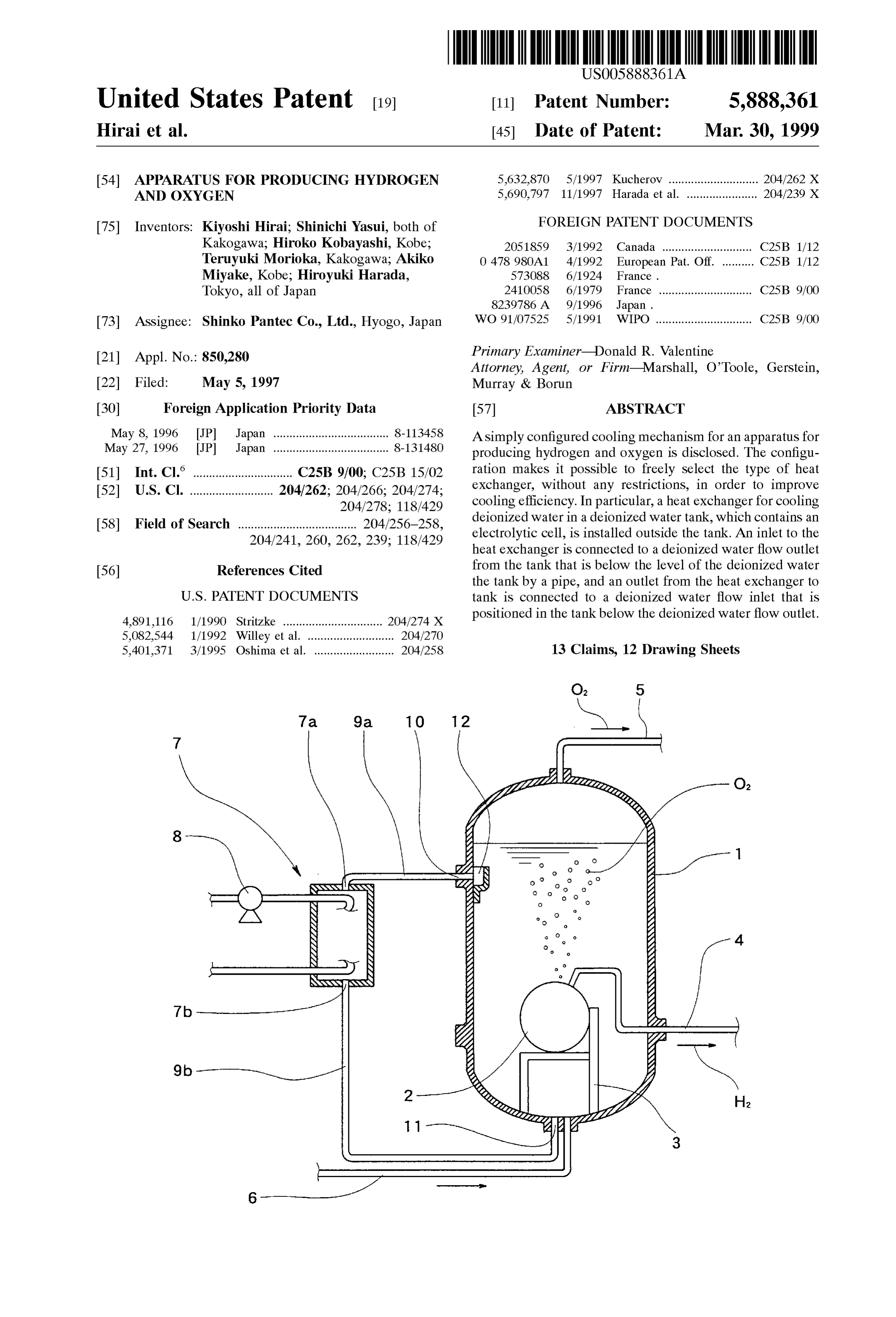
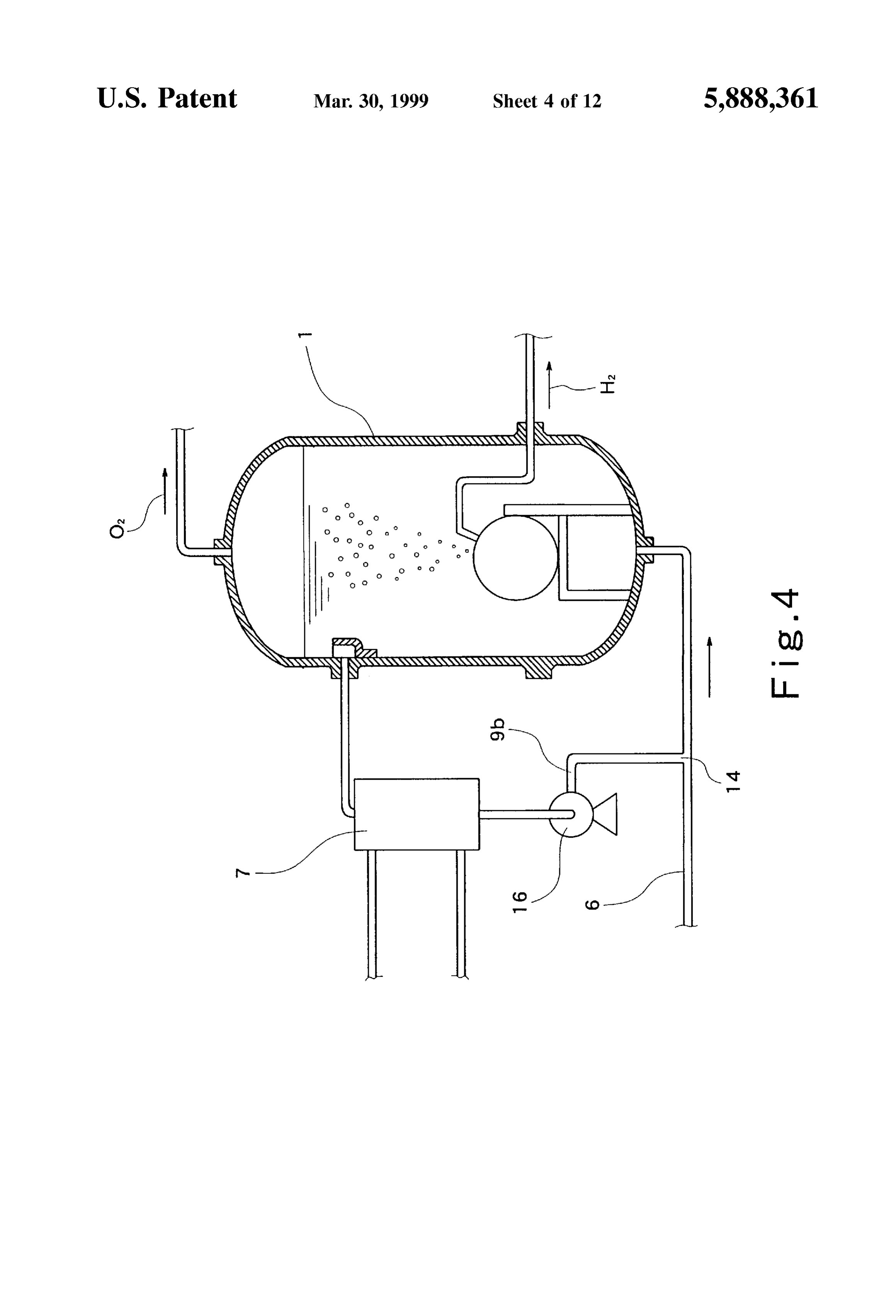
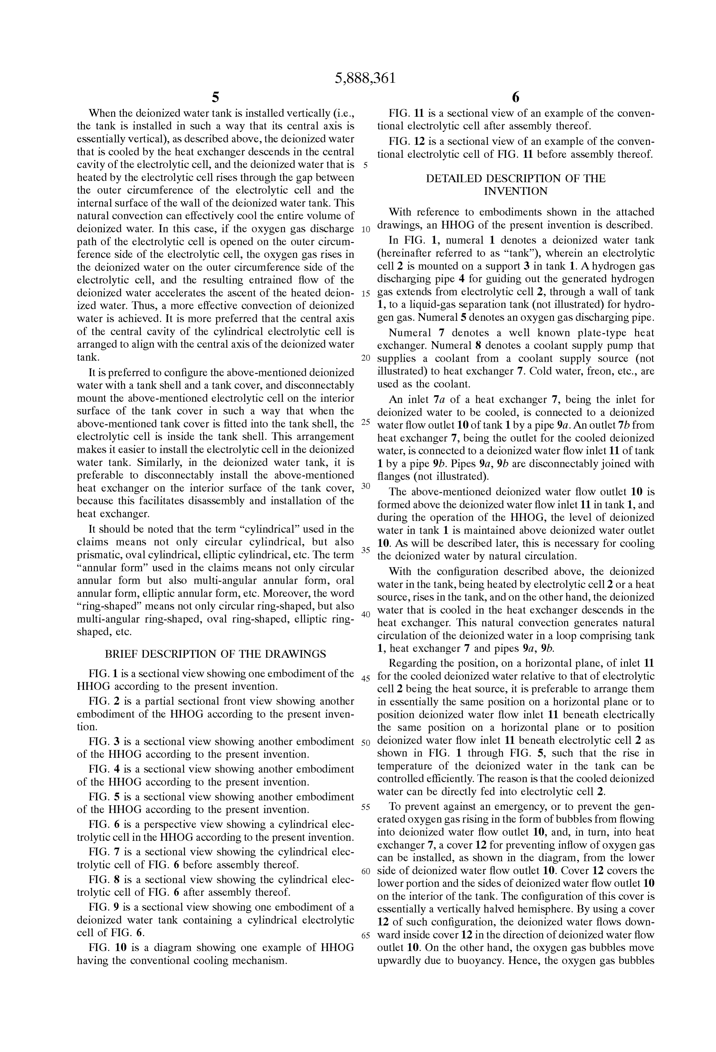
When the deionized water tank is installed vertically (i.e., FIG. 11 is a sectional view of an example of the conven the tank is installed in Such a way that its central axis is tional electrolytic cell after assembly thereof. essentially vertical), as described above, the deionized water FIG. 12 is a sectional view of an example of the conven that is cooled by the heat eXchanger descends in the central tional electrolytic cell of FIG. 11 before assembly thereof. cavity of the electrolytic cell, and the deionized water that is heated by the electrolytic cell rises through the gap between DETAILED DESCRIPTION OF THE the outer circumference of the electrolytic cell and the INVENTION internal Surface of the wall of the deionized water tank. This natural convection can effectively cool the entire Volume of With reference to embodiments shown in the attached deionized water. In this case, if the oxygen gas discharge drawings, an HHOG of the present invention is described. path of the electrolytic cell is opened on the Outer circum In FIG. 1, numeral 1 denotes a deionized water tank ference Side of the electrolytic cell, the oxygen gas rises in (hereinafter referred to as “tank”), wherein an electrolytic the deionized water on the outer circumference Side of the cell 2 is mounted on a Support 3 in tank 1. A hydrogen gas electrolytic cell, and the resulting entrained flow of the discharging pipe 4 for guiding out the generated hydrogen deionized water accelerates the ascent of the heated deion 15 gas extends from electrolytic cell 2, through a wall of tank ized water. Thus, a more effective convection of deionized 1, to a liquid-gas separation tank (not illustrated) for hydro water is achieved. It is more preferred that the central axis gen gas. Numeral 5 denotes an OXygen gas discharging pipe. of the central cavity of the cylindrical electrolytic cell is Numeral 7 denotes a well known plate-type heat arranged to align with the central axis of the deionized water eXchanger. Numeral 8 denotes a coolant Supply pump that tank. Supplies a coolant from a coolant Supply Source (not It is preferred to configure the above-mentioned deionized illustrated) to heat exchanger 7. Cold water, freon, etc., are water with a tank shell and a tank cover, and disconnectably used as the coolant.
mount the above-mentioned electrolytic cell on the interior An inlet 7a of a heat exchanger 7, being the inlet for Surface of the tank cover in Such a way that when the deionized water to be cooled, is connected to a deionized above-mentioned tank cover is fitted into the tank shell, the 25 water flow outlet 10 of tank 1 by a pipe 9a. An outlet 7b from electrolytic cell is inside the tank Shell. This arrangement heat eXchanger 7, being the outlet for the cooled deionized makes it easier to install the electrolytic cell in the deionized water, is connected to a deionized water flow inlet 11 of tank water tank. Similarly, in the deionized water tank, it is 1 by a pipe 9b. Pipes 9a, 9b are disconnectably joined with preferable to disconnectably install the above-mentioned flanges (not illustrated).
heat eXchanger on the interior Surface of the tank cover, The above-mentioned deionized water flow outlet 10 is because this facilitates disassembly and installation of the formed above the deionized water flow inlet 11 in tank 1, and heat eXchanger. during the operation of the HHOG, the level of deionized It should be noted that the term "cylindrical used in the water in tank 1 is maintained above deionized water outlet claims means not only circular cylindrical, but also 35 10. As will be described later, this is necessary for cooling prismatic, Oval cylindrical, elliptic cylindrical, etc. The term the deionized water by natural circulation. “annular form' used in the claims means not only circular With the configuration described above, the deionized annular form but also multi-angular annular form, oral water in the tank, being heated by electrolytic cell 2 or a heat annular form, elliptic annular form, etc. Moreover, the word Source, rises in the tank, and on the other hand, the deionized “ring-shaped” means not only circular ring-shaped, but also 40 water that is cooled in the heat eXchanger descends in the multi-angular ring-shaped, oval ring-shaped, elliptic ring heat eXchanger. This natural convection generates natural shaped, etc. circulation of the deionized water in a loop comprising tank BRIEF DESCRIPTION OF THE DRAWINGS 1, heat exchanger 7 and pipes 9a, 9b.
Regarding the position, on a horizontal plane, of inlet 11
FIG. 1 is a sectional view showing one embodiment of the 45 for the cooled deionized water relative to that of electrolytic HHOG according to the present invention. cell 2 being the heat Source, it is preferable to arrange them FIG. 2 is a partial Sectional front view showing another in essentially the same position on a horizontal plane or to embodiment of the HHOG according to the present inven position deionized water flow inlet 11 beneath electrically tion. the same position on a horizontal plane or to position FIG. 3 is a sectional view showing another embodiment 50 deionized water flow inlet 11 beneath electrolytic cell 2 as of the HHOG according to the present invention. shown in FIG. 1 through FIG. 5, such that the rise in FIG. 4 is a sectional view showing another embodiment temperature of the deionized water in the tank can be of the HHOG according to the present invention. controlled efficiently. The reason is that the cooled deionized FIG. 5 is a sectional view showing another embodiment 55 water can be directly fed into electrolytic cell 2. of the HHOG according to the present invention. To prevent against an emergency, or to prevent the gen FIG. 6 is a perspective view showing a cylindrical elec erated oxygen gas rising in the form of bubbles from flowing into deionized water flow outlet 10, and, in turn, into heat trolytic cell in the HHOG according to the present invention. eXchanger
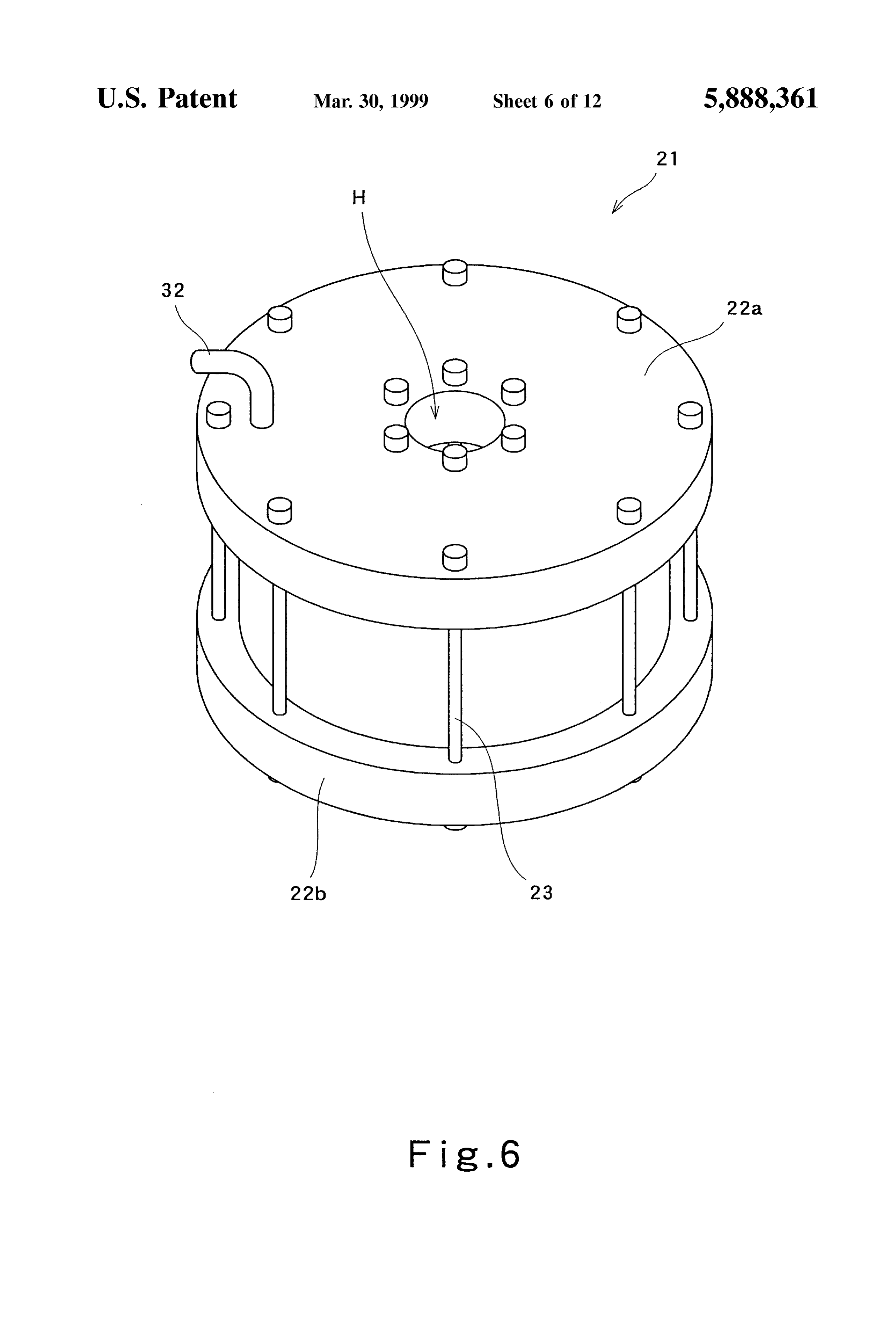
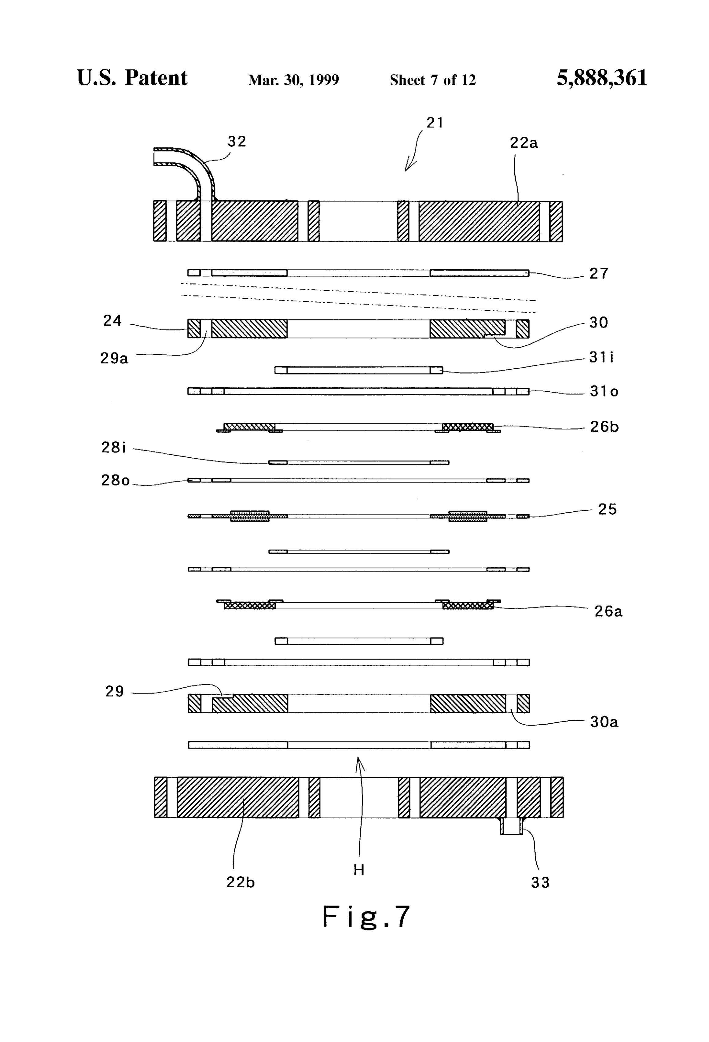
FIG. 7 is a sectional view showing the cylindrical elec can be installed, 7, a cover 12 for preventing inflow of oxygen gas trolytic cell of FIG. 6 before assembly thereof. as shown in the diagram, from the lower 60 side of deionized water flow outlet 10. Cover 12 covers the
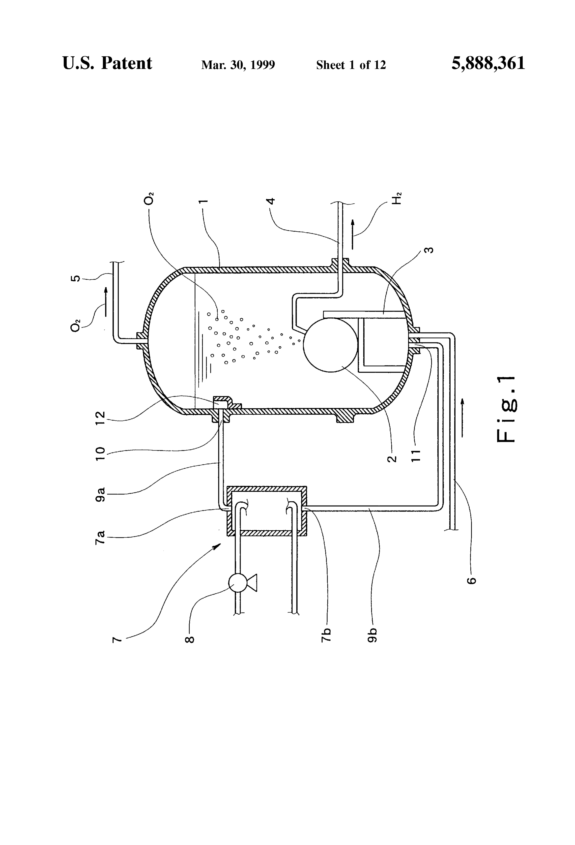
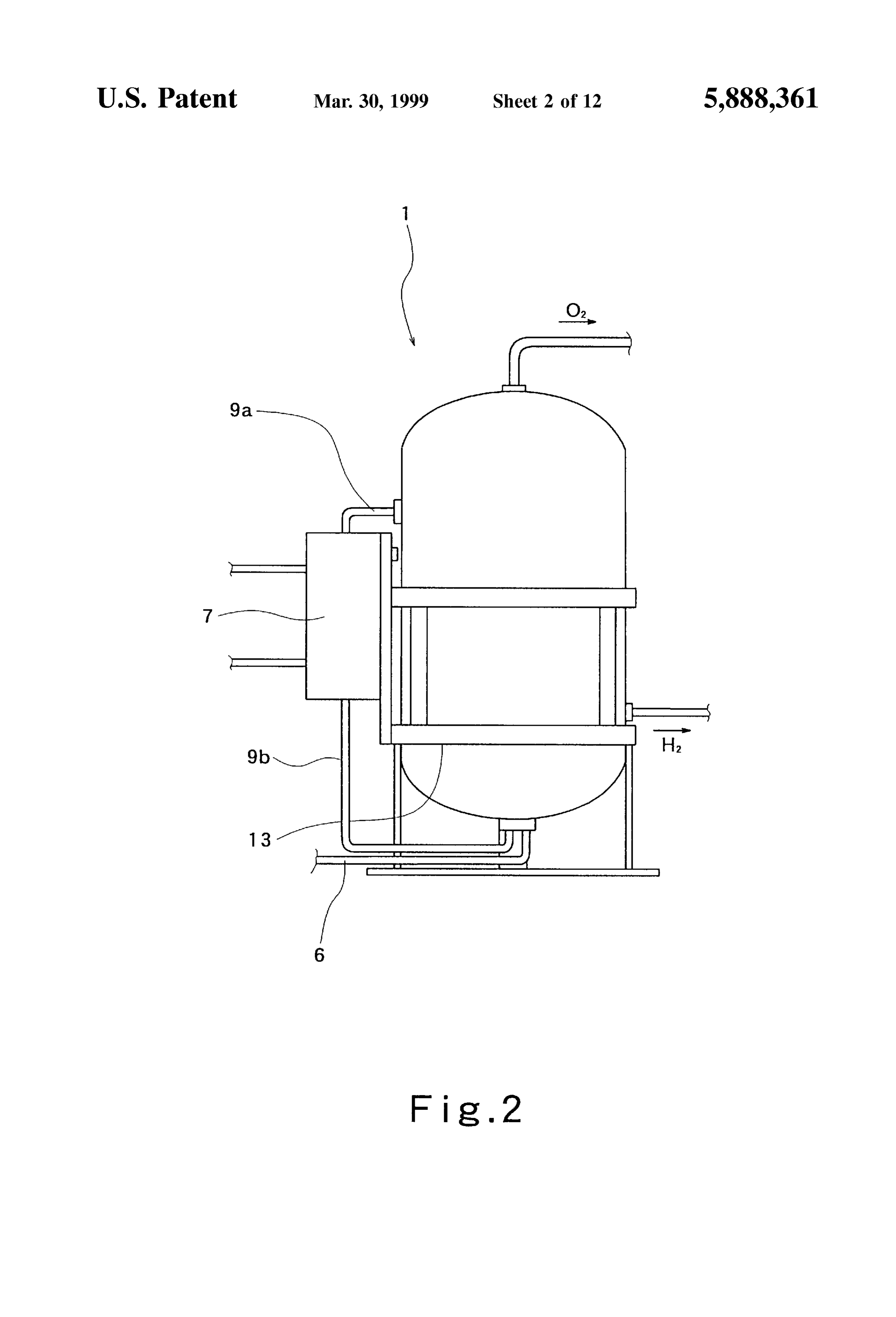
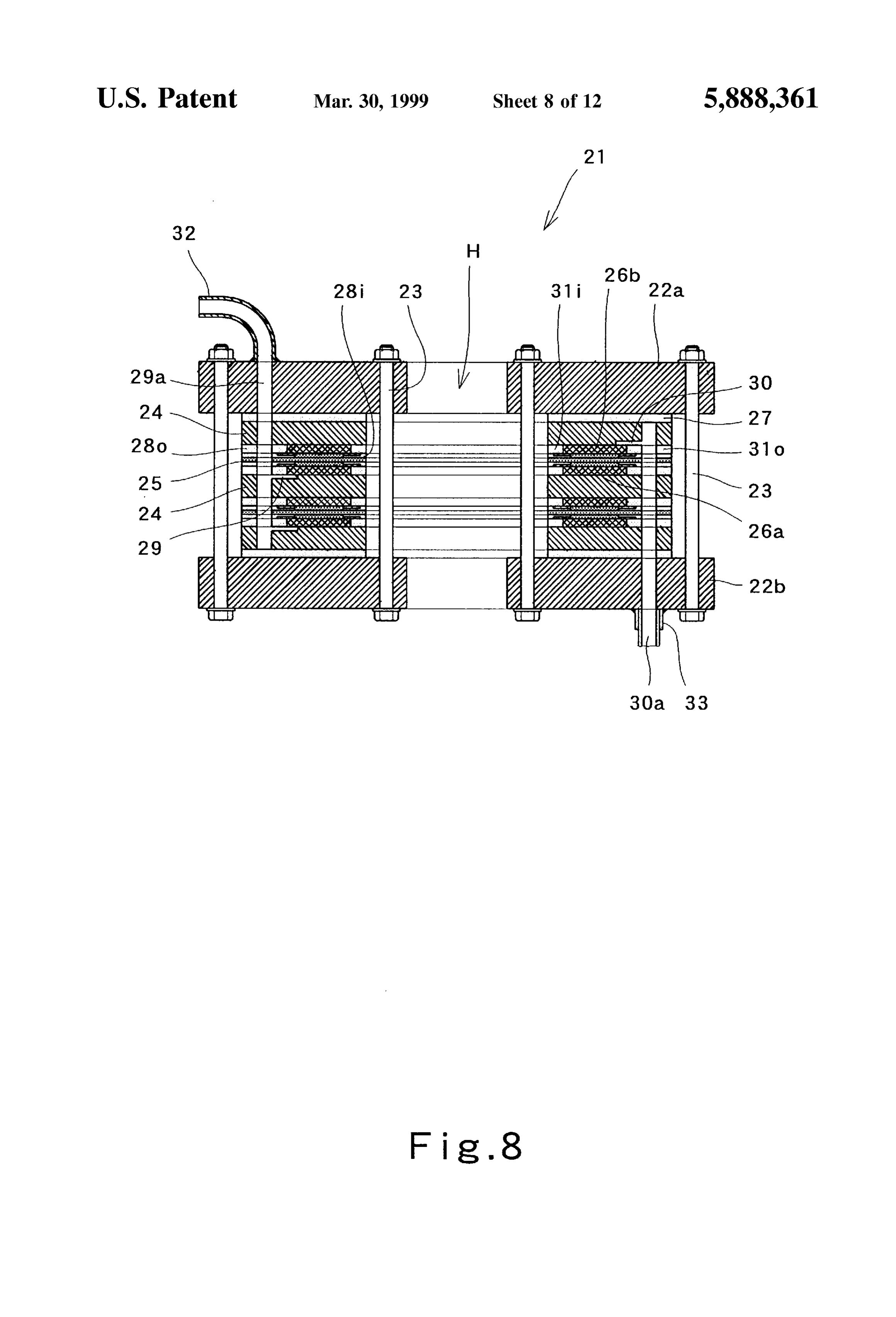
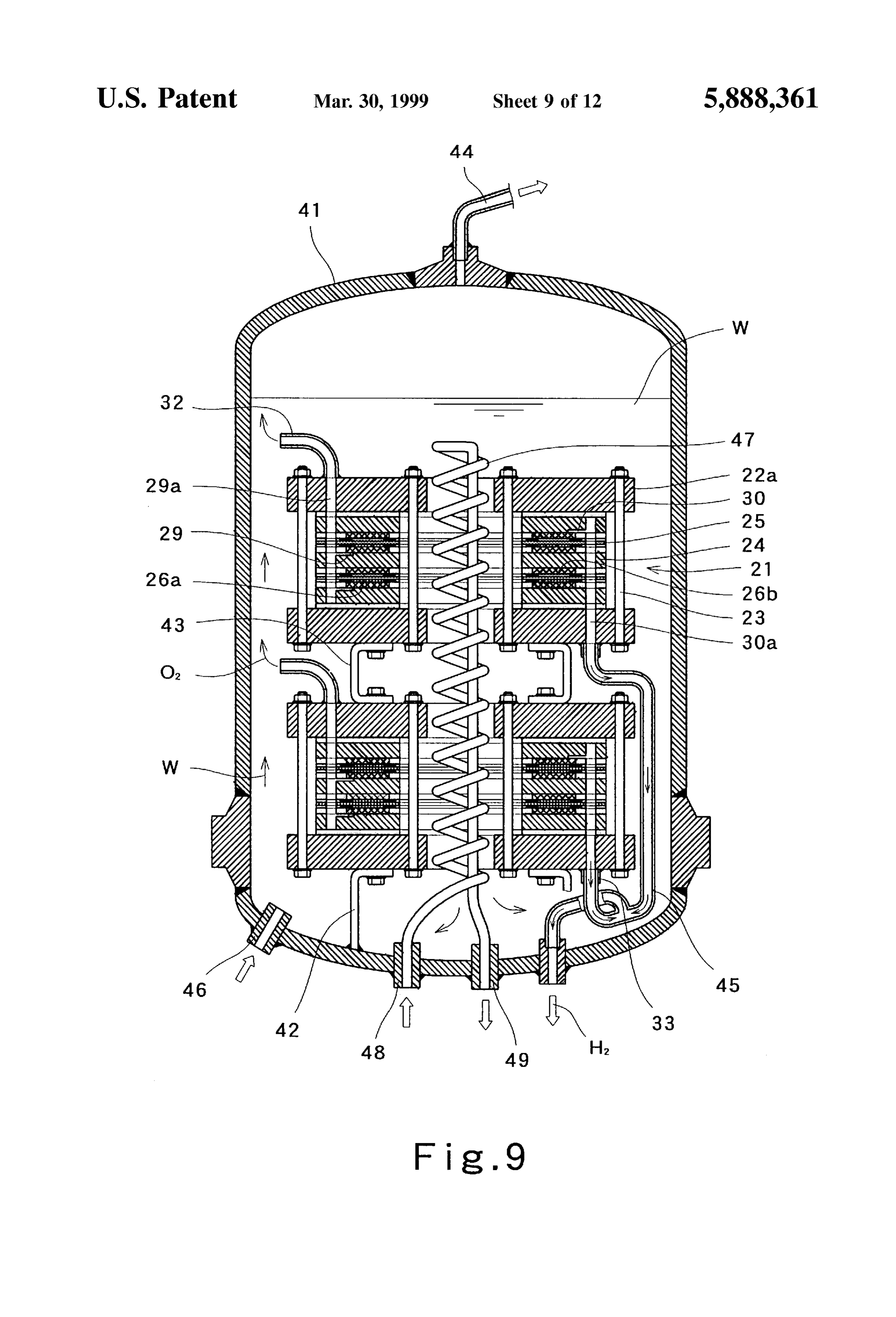
FIG. 8 is a sectional view showing the cylindrical elec lower portion and the sides of deionized water flow outlet 10 trolytic cell of FIG. 6 after assembly thereof. on the interior of the tank. The configuration of this cover is FIG. 9 is a sectional view showing one embodiment of a essentially a vertically halved hemisphere. By using a cover deionized water tank containing a cylindrical electrolytic 12 of Such configuration, the deionized water flows down cell of FIG. 6. 65 ward inside cover 12 in the direction of deionized water flow FIG. 10 is a diagram showing one example of HHOG outlet 10. On the other hand, the oxygen gas bubbles move having the conventional cooling mechanism. upwardly due to buoyancy. Hence, the oxygen gas bubbles
Page 17
are not entrained by the flow of deionized water. Thus, the cooled directly. As a result, thermal degradation of the parts oxygen gas bubbles cannot flow into heat eXchanger 7. The of electrolytic cell 2, Such as Solid electrolyte membranes configuration of cover 12 is not particularly defined. It is and gaskets (not illustrated) can be effectively prevented. Sufficient that the configuration of cover 12 can prevent It should be noted that the configuration of directly rising oxygen gas bubbles from passing near deionized connecting the above-mentioned pipe 9b to electrolytic cell water outlet 10.
The cooling mechanism shown in FIG. 2 uses the same 2 is not limited to the cooling mechanism shown in FIG. 5 principle of cooling deionized water as the cooling mecha and can be applicable to the cooling mechanisms shown in nism of FIG. 1, but the above-described heat exchanger 7 is FIG. 1, FIG. 2, FIG. 3, and FIG. 4. mounted directly on the tank 1 to provide an integrated unit. In the following, the cooling mechanism of the HHOG In the present embodiment, heat eXchanger 7 is discon according to the present invention is described from the nectably mounted on a stand 13 of tank 1 by means of bolts Viewpoint of function by comparing the cooling efficiency of (not illustrated). The pipes 9a, 9b are disconnectably joined the cooling mechanisms described above to that of a con with flanges (not illustrated). ventional cooling mechanism.
With the above-mentioned arrangement, the Support for 15 Generally speaking, the heat transfer coefficient (Cla) of tank 1 can be used as Support 13 of heat eXchanger 7, and plate-type heat eXchangers used in the above-mentioned it is not necessary to install another Support for the heat embodiments is from 1000 to 3000 kcal/m/hr/°C. (the mean exchanger 7. Furthermore, the lengths of pipes 9a, 9b can be value is set at 2000 kcal/m/hr/°C), and the heat transfer reduced. This in turn makes the apparatus more compact. coefficient (C.b) of the coil tube-type heat exchangers used in According to the present invention, integration of tank 1 the prior art is from 200 to 1000 kcal/m/hr/°C. (the mean and heat exchanger 7 is not limited to an embodiment with value is set at 500 kcal/mi/hr/°C.).
a Stand. For example, if heat eXchanger 7 is light in weight, On the other hand, the heat generation (Q) of ordinary it can be supported by above-described pipes 9a, 9b, alone. electrolytic cells used in the prior art and in the embodiments Tank 1 is used at high preSSure, and to prevent leakage of is 25,800 kcal/hr, which is calculated from the current of 600 deionized water from tank 1, it is desirable to reduce the 25 A and the voltage of 50 V.
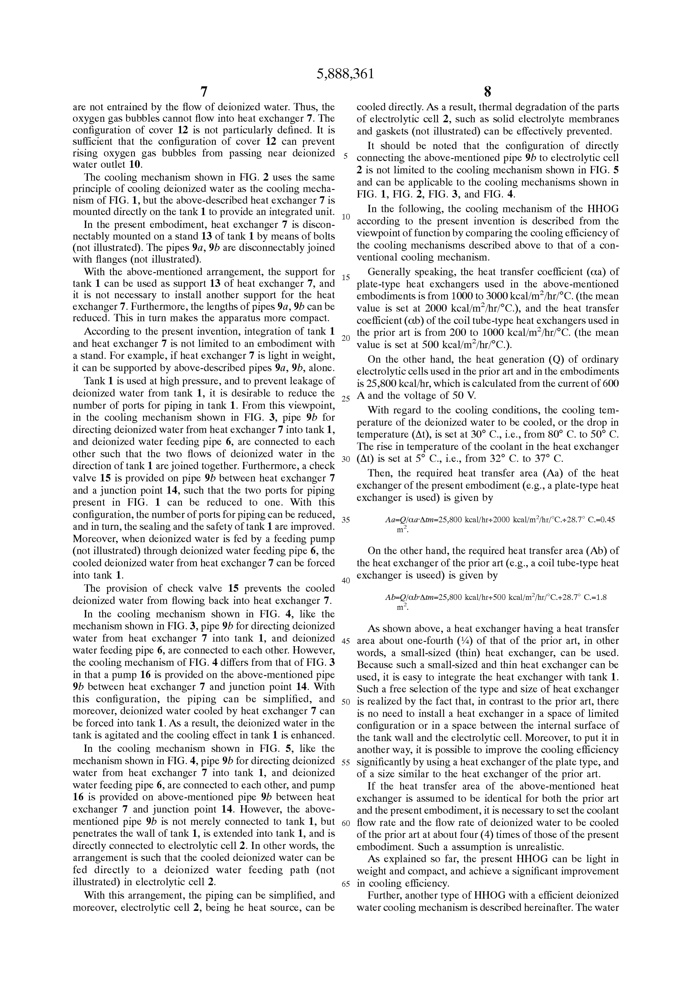
number of ports for piping in tank 1. From this viewpoint, With regard to the cooling conditions, the cooling tem in the cooling mechanism shown in FIG. 3, pipe 9b for perature of the deionized water to be cooled, or the drop in directing deionized water from heat eXchanger 7 into tank 1, temperature (At), is set at 30° C., i.e., from 80° C. to 50° C. and deionized water feeding pipe 6, are connected to each The rise in temperature of the coolant in the heat eXchanger other Such that the two flows of deionized water in the direction of tank 1 are joined together. Furthermore, a check (At) is set at 5° C., i.e., from 32° C. to 37° C. valve 15 is provided on pipe 9b between heat exchanger 7 exchanger Then, the required heat transfer area (Aa) of the heat and a junction point 14, Such that the two ports for piping eXchanger of is the present embodiment (e.g., a plate-type heat used) is given by present in FIG. 1 can be reduced to one. With this configuration, the number of ports for piping can be reduced, 35 Aa=Q/Ca"Atm=25,800 kcal/hr+2000 kcal/m/hr/C.-28.7 C.=0.45 and in turn, the Sealing and the Safety of tank 1 are improved. .
Moreover, when deionized water is fed by a feeding pump (not illustrated) through deionized water feeding pipe 6, the On the other hand, the required heat transfer area (Ab) of cooled deionized water from heat eXchanger 7 can be forced the heat exchanger of the prior art (e.g., a coil tube-type heat 40 exchanger is useed) is given by into tank 1.
The provision of check valve 15 prevents the cooled deionized water from flowing back into heat eXchanger 7.
In the cooling mechanism shown in FIG. 4, like the mechanism shown in FIG. 3, pipe 9b for directing deionized AS shown above, a heat eXchanger having a heat transfer water from heat eXchanger 7 into tank 1, and deionized 45 area about one-fourth (4) of that of the prior art, in other water feeding pipe 6, are connected to each other. However, words, a Small-sized (thin) heat exchanger, can be used. the cooling mechanism of FIG. 4 differs from that of FIG. 3 Because Such a Small-sized and thin heat eXchanger can be in that a pump 16 is provided on the above-mentioned pipe used, it is easy to integrate the heat eXchanger with tank 1. 9b between heat exchanger 7 and junction point 14. With Such a free Selection of the type and Size of heat eXchanger this configuration, the piping can be simplified, and 50 is realized by the fact that, in contrast to the prior art, there moreover, deionized water cooled by heat eXchanger 7 can is no need to install a heat eXchanger in a Space of limited be forced into tank 1. As a result, the deionized water in the configuration or in a Space between the internal Surface of tank is agitated and the cooling effect in tank 1 is enhanced. the tank wall and the electrolytic cell. Moreover, to put it in In the cooling mechanism shown in FIG. 5, like the another way, it is possible to improve the cooling efficiency mechanism shown in FIG. 4, pipe 9b for directing deionized 55 Significantly by using a heat eXchanger of the plate type, and water from heat eXchanger 7 into tank 1, and deionized of a size Similar to the heat eXchanger of the prior art. water feeding pipe 6, are connected to each other, and pump If the heat transfer area of the above-mentioned heat 16 is provided on above-mentioned pipe 9b between heat eXchanger is assumed to be identical for both the prior art exchanger 7 and junction point 14. However, the above and the present embodiment, it is necessary to Set the coolant mentioned pipe 9b is not merely connected to tank 1, but 60 flow rate and the flow rate of deionized water to be cooled penetrates the wall of tank 1, is extended into tank 1, and is of the prior art at about four (4) times of those of the present directly connected to electrolytic cell 2. In other words, the embodiment. Such a assumption is unrealistic. arrangement is Such that the cooled deionized water can be As explained so far, the present HHOG can be light in fed directly to a deionized water feeding path (not weight and compact, and achieve a Significant improvement illustrated) in electrolytic cell 2. 65 in cooling efficiency.
With this arrangement, the piping can be simplified, and Further, another type of HHOG with a efficient deionized moreover, electrolytic cell 2, being he heat Source, can be water cooling mechanism is described hereinafter. The water
Page 18
cooling efficiency of said HHOG is highly improved by explained later, to guide the OXygen gas generated in elec means of modifying an electrolytic cell of said HHOG, as trolytic cell 21 out of the outer circumference of electrolytic shown in FIGS. 6 through 9. cell 21. A nipple 33 is provided on the bottom of lower end A circular cylindrical electrolytic cell 21 is shown in FIG. plate 22b, and is connected to hydrogen gas duct 30a. This 6 through 8. Numerals 22a and 22b denote end plates. The 5 is, as will be explained later, to connect a hydrogen gas components of electrolytic cell 21 described below are held discharging pipe 45 that guides the hydrogen generated in between end plates 22a, 22b by tightening bolts 23. A electrolytic cell 21 out of a deionized water tank 41. plurality of bolts 23 are tightened on the outside the outer With the configuration described above, the present elec circumference Side, and on the outside the inner circumfer trolytic cell 21 is formed into a circular cylinder having a ence Side, of circular cylindrical electrolytic cell 21, respec cavity H in the center thereof.
tively. As shown in FIG. 8, “the outside inner circumfer In the above-mentioned embodiment, as shown in FIG. 6 ence” means the central-cavity-Side of the outside of the through FIG. 8, an electrolytic cell having two solid elec inner circumference of the cell. Thus, as bolts are provided trolyte membranes has been described. The invention is not both on the Outer circumference Side and the inner circum limited to Such an embodiment, and any number of Solid ference Side, electrolytic cell 21 has a greater rigidity than 15 electrolyte membranes can be used to provide the required conventional electrolytic cells. Furthermore, as the number quantities of Oxygen gas or hydrogen gas. of clamping bolts is increased, bolts of a Smaller diameter FIG. 9 shows deionized water tank 41 in which the can be used. above-mentioned electrolytic cells 21 are provided in two Numeral 24 denotes a circular ring-shaped electrode Stages. Deionized water tank 41 is a primary component of plate, and numeral 25 denotes a circular ring-shaped Solid the HHOG. Deionized water W is stored in deionized water electrolyte membrane. Numerals 26a and 26b denote circu tank 41, and deionized water W is directed into electrolytic lar ring-shaped porous conductors, respectively. Numeral 27 cell 21 and electrolyzed. Numeral 42 denotes a stand for denotes a circular ring-shaped end gasket, and numeral 28 fixing electrolytic cell 21 onto the bottom of deionized water denotes a circular ring-shaped protective sheet. Numeral 29 tank 41. Numeral 43 denotes a connector that connects denotes an oxygen gas discharging path, and numeral 29a 25 electrolytic cells 21 to each other.
denotes an oxygen gas discharging duct. Numeral 30 Oxygen gas generated in electrolytic cell 21 is discharged denotes a hydrogen gas discharging path, and numeral 30a out of the above-mentioned elbow 32 into the deionized denotes a hydrogen gas discharging duct. The deionized water on the outer circumference Side of electrolytic cell 21. water feeding path is not shown in the diagram, but it has a Then, the oxygen gas is directed through an oxygen gas configuration Similar to that of hydrogen gas discharging discharging pipe 44, which is connected onto the top of path 30. deionized water tank 41, and fed into a dehumidifier (not Electrolytic cell 21 comprises a plurality of electrolytic illustrated). The oxygen gas is collected after dehumidifica cell units Stacked together. Each electrolytic cell unit is tion.
provided with an anode chamber and a cathode chamber that On the other hand, hydrogen gas generated in electrolytic are separated by electrolytic membrane 25, and located 35 cell 21 is directed through hydrogen gas discharging pipe 45, between electrode plates 24. Electrolytic cell units adjacent which is connected to above-mentioned nipple 33 and to each other have single electrode plate 24 for common use penetrates the wall of deionized water tank 41, and is fed as a bipolar-type electrode plate. Therefore, an electrode into a gas-liquid separator tank (not illustrated). Then, the plate 24 between electrolytic cell units adjacent to each other hydrogen gas is directed to a dehumidifier (not illustrated). has opposing Surfaces that have opposite polarity when 40 The hydrogen gas is collected after dehumidification. energized. Numeral 46 denotes a deionized water feeding port to which Both the anode chamber and the cathode chamber are a deionized water feeding pipe (not illustrated) is connected. formed as annular compartments being isolated on their A tube-type heat exchanger 47 is installed in cavity H at inner circumferences and on their outer circumferences from the center of electrolytic cells 21. One end of heat eXchanger the outside with intermediate gaskets 31. 45 47 is connected to a coolant inlet 48 that is formed in the Intermediate gasket 31 isolates anode chamber 26a or deionized water tank wall, and the other end is connected to cathode chamber 26b from the outside on the inner circum a coolant outlet 49 that is formed in the deionized water tank ference Side and on the outer circumference Side. Interme wall. Cold water, freon, etc., are used as the coolant. diate gasket 31 consists of two members, a gasket 31i on the With the configuration described above, in deionized inner circumference side of electrolytic cell as an inner Side 50 water tank 41, deionized water W that is cooled by heat closing member, and a gasket 31O on the outer circumfer eXchanger 47 descends through cavity H at the center of ence Side thereof as an Outer Side closing member. A positive electrolytic cells 21, and the deionized water W that is sheet 28 consists of two members; a sheet 28i on the inner heated by electrolytic cells 21 rises, partly due to ascent of circumference side of the electrolytic cell and a sheet 28o on the generated oxygen gas, on the Outer circumference Side of the Outer circumference Side thereof. They are designed to 55 electrolytic cell 21. Thus, an effective convection is gener make anode chamber 26a and the cathode chamber 26b in ated to improve the cooling efficiency of the deionized water annular forms, respectively. The anode chamber and the as a whole.
cathode chamber are provided with porous conductors 26a, Moreover, in contrast to the prior art, the heat eXchanger 26b, respectively. The above-mentioned oxygen gas dis is not installed in the annular space outside the electrolytic charging path 29 connects anode chamber 26a and oxygen 60 cell, thus, the deionized water tank can be made more gas duct 29a. The hydrogen gas discharging path 30 con compact. Moreover, although not illustrated, the deionized nects cathode chamber 26b and hydrogen gas duct 30a. water tank can be configured with two members, e.g., a shell Preferably, titanium of a plate type is used as a material and a head plate each having a flange, or with three of electrode plates 24. AS for porous conductors 26a, 26b, a members, e.g., a shell and two head plates each having a mesh of titanium can be used. 65 flange. These members can be formed Such that they are An elbow 32 is provided on the top of upper end plate 22a joined by flange connections. In this way, the above and is connected to oxygen gas duct 29a. This is, as will be mentioned electrolytic cell 21 and/or the above-mentioned
Page 19
heat eXchanger 47 can be installed in advance on the internal With an HHOG of the present invention incorporating a Surface of one head plate. With Such a configuration, disas cylindrical electrolytic cell, the heat eXchanger can be Sembly and assembly of deionized water tank 41 is accom installed in the central cavity of the cylindrical electrolytic plished more easily. cell, and the deionized water tank can be more compact. With respect to the solid electrolyte membrane, a solid Moreover, a very suitable route is provided for the natural polymer electrolyte can be formed into a membrane, for convection of deionized water to effectively cool the entire example, a Solid polymer electrolyte membrane, wherein a volume of deionized water, wherein the deionized water that porous anode and a porous cathode, each of a precious is cooled by the heat eXchanger descends in the above metal, and particularly a metal of the platinum group, are mentioned cavity and the deionized water rises through the bonded by chemical plating onto opposing faces of a cation gap between the Outer circumference of the electrolytic cell eXchange membrane, Such as a cation eXchange membrane and the inner Surface of the wall of the deionized water tank. made of fluorocarbon resin containing Sulphonic acid Moreover, as both the outer circumference side and the groups, for example, NAFION 117, available from DuPont inner circumference Side of the electrolytic cell are clamped deNemours, Inc., Wilmington, Del. In this case, both elec and compressed, the rigidity of the electrolytic cell is trodes preferably are made of platinum. In particular, when both electrodes are of a two-layer construction of platinum 15 improved relative to the conventional electrolytic cells. What is claimed is:
and iridium, it is possible to electrolyze using a high current 1. An apparatus for producing hydrogen and oxygen density, for example, at 80° C. and 200 A/dmf, for as long having as about four years, whereas a conventional Solid electrolyte therein,a deionized water tank containing an electrolytic cell membrane in which the electrodes are in physical contact with an ion exchange membrane can be electrolyzed at 50 to wherein a heat eXchanger for cooling deionized water in 70 A/dm. In this case, in addition to the above-mentioned the deionized water tank is operatively connected to, iridium, it is possible to use a Solid polymer electrolyte and positioned outside of, the deionized water tank, membrane of a multi-layer construction wherein two or wherein an inlet to the heat eXchanger is connected to more metals of the platinum group are plated. It is possible an outlet of the deionized water tank, Said tank outlet to achieve operation at a high current density by using 25 being adapted for location below a level of deionized above-mentioned membrane. water in an upper portion of the deionized water tank, When a solid electrolyte membrane of the present appli and wherein an outlet from the heat eXchanger is cation is constructed Such that electrodes of a precious metal connected to an inlet of the deionized water tank, Said or metals are bonded by chemical plating onto opposing tank inlet being below the tank outlet in a lower portion faces of Solid polymer electrolyte, water is not present of the deionized water tank, Said tank outlet guiding out between the solid polymer electrolyte and either electrode. deionized water at the upper portion of the deionized Hence, there is neither Solution resistance nor gas resistance, water tank into the heat eXchanger, and Said tank inlet and in turn, contact resistance between the Solid polymer Supplying cooled deionized water from the heat electrolyte and each electrode is low, the Voltage is low, and eXchanger into the lower portion of the deionized water current distribution is even. As a result, it is possible to use 35 tank.
a higher current density and electrolyze water at a higher 2. The apparatus of claim 1 further comprising a cover on temperature and at a higher pressure, which results in the deionized water flow outlet on the interior of the deion production of high purity oxygen and hydrogen gases with ized water tank to prevent oxygen gas from flowing into the a greater efficiency. deionized water flow outlet.
Other Solid electrolyte membranes, Such as a ceramic 40 3. The apparatus of claim 1 wherein the tank inlet is membrane, can be used instead of the Solid polymer elec adapted below the electrolytic cell for Supplying cooled trolyte membrane. deionized water beneath the electrolytic cell. In the above-mentioned embodiment, the present inven 4. An apparatus for producing hydrogen and oxygen tion was described as an example of an apparatus for having a deionized water tank containing an electrolytic cell producing hydrogen and oxygen of high purity, wherein 45 therein, electrolytic cells are installed in two Stages. The invention is wherein a heat eXchanger for cooling deionized water in not limited to this embodiment, and can be applied to an the deionized water tank is operatively connected to, apparatus wherein an electrolytic cell is installed in one and positioned outside of, the deionized water tank, Stage or electrolytic cells are installed in three or more wherein an inlet to the heat eXchanger is connected to Stages. 50 an outlet of the deionized water tank, Said tank outlet In the present embodiment, a vertical tank (i.e., the central being adapted for location below a level of deionized axis of the tank is virtually vertical) is used by way of water in an upper portion of the deionized water tank, example. In the present invention, however, the tank is not Said tank outlet guiding out deionized water at the limited to a vertical one, and a horizontal one (i.e., the upper portion of the deionized water tank into the heat central axis of the tank is essentially horizontal) can be used. 55 eXchanger, and an outlet from the heat eXchanger is With the use of a cooling mechanism of the present operatively connected to the electrolytic cell in the invention, deionized water can be cooled while it is made to deionized water tank to feed deionized water to the circulate by natural convection. Hence, no special circula electrolytic cell.
tion apparatuses are required, and the resulting configuration 5. The apparatus of claim 4 further comprising a cover on is simple. Naturally, it is possible to install apparatuses for 60 the deionized water flow outlet on the interior of the deion forced circulation (Such as pumps). Moreover, because the ized water tank to prevent oxygen gas from flowing into the heat eXchanger is installed outside the tank, the tank can be deionized water flow outlet.
made lighter in weight and more compact. This, in turn, 6. An apparatus for producing hydrogen and oxygen reduces the production costs, transport costs, and installation comprising:
work costs. The type of heat eXchanger can be freely 65 an electrolytic cell having an anode chamber and a Selected according to the Service conditions and installation cathode chamber, Said chambers separated by an elec conditions. This, in turn, improves cooling efficiency. trolyte membrane and located between electrode plates,
Page 20
and a deionized water tank containing Said electrolytic 9. The apparatus of claim 6 comprising a plurality of Said cell therein, cylindrical electrolytic cells Stacked together. wherein the anode chamber and the cathode chamber each 10. The apparatus of claim 6 wherein a path for discharg are formed as annular compartments being Sealed on ing generated oxygen gas is formed to connect the anode their inner circumferences and on their outer 5 chambers and a port of a discharging of oxygen gas on the circumferences, Such that the electrolytic cell is cylin outer circumference Side of the cylindrical electrolytic cell. drical having a cavity at the center thereof, 11. The apparatus of claim 6 wherein the central axis of and wherein a heat eXchanger for cooling is deionized the central cavity of the cylindrical electrolytic cell is water in the deionized water tank is positioned in the arranged to align with the central axis of the deionized water central cavity of the electrolytic cell.
7. The apparatus of claim 6 wherein said cylindrical tank.
electrolytic cell compriseS ring-shaped end plates at each 12. The apparatus of claim 6 wherein the deionized water end thereof, and a plurality of clamping means located tank comprises a tank shell and a tank cover, wherein the outside the anode chamber and the cathode chamber on both cylindrical electrolytic cell is disconnectably mounted on the the inner circumference Side and the Outer circumference 15 inner Side of the tank cover, and the cylindrical electrolytic Side thereof, wherein the components of the anode chamber cell is arranged Such that when the tank cover is fit on the and the cathode chamber are clamped between the end plates tank Shell, the cylindrical electrolytic cell is positioned by the clamping means. inside the tank shell.
8. The apparatus of claim 6 wherein said cylindrical 13. The apparatus of claim 6 wherein the deionized water electrolytic cell comprises a ring-shaped electrolyte membrane, ring-shaped porous conductors provided on each tank comprises a tank shell and a tank cover, wherein the Side of the membrane, ring-shaped electrode plates provided heat eXchanger is disconnectably mounted on the inner Side on the outer Sides of each of the porous conductors, an outer of the tank cover, and the heat eXchanger is positioned Such Side closing member provided on the outer circumference 25 that when the tank cover is fit on the tank shell, the heat Side of each porous conductor, and an inner Side closing eXchanger is positioned inside the tank shell. member provided on the inner circumference Side of the porous conductors.
Provenance
- Collection
- Cited prior art
- Original PDF
- patentimages.storage.googleapis.com →
- Filed
- 1997-05-05
- Pages
- 20
- Method
- pdftotext (the PDF's own text layer) + pdftoppm 300dpi page scans
- Source
- Google Patents bibliographic record
- Granted
- 1999-03-30
- Inventors
- Kiyoshi Hirai; Shinichi Yasui; Hiroko Kobayashi; Teruyuki Morioka; Akiko Miyake; Hiroyuki Harada; Shinko Pantec Co Ltd
- Transcribed from
- patentimages.storage.googleapis.com →