patent · US5882502
Electrochemical system and method
16 March 1999
Page 1 — bibliographic record
United States Patent (19) 11 Patent Number: 5,882,502 Gomez (45) Date of Patent: Mar 16, 1999 54 ELECTROCHEMICAL SYSTEMAND 3,737,381 6/1973 White et al. ........................ 204/257 X METHOD 3,788.965 1/1974 Holsinger ................................ 204/234 3,926,752 12/1975 Loretto et al. 205/582 75 Inventor: Rodolfo Gomez, Urrbrae, Australia 4,061,552 12/1977 Everett .................................... 205/543 4,159,232 6/1979 Bacon et al. ............................ 205/347 73 Assignee: RMG Services Pty Ltd., Adelaide, 4,181,588 1/1980 Wong et al. ............................ 205/600 Australia 4,214,964 7/1980 Cannell ................................... 205/594 4,282,082 8/1981 Cook et al. ......... 204/269 X 4,594,132 6/1986 Satchell, Jr. et al. ................... 205/581 21 Appl. No.:710,983 4,935,109 6/1990 Dugan ................ 204/269 X 5,183,544 2/1993 Weber et al. ........................... 204/252 22 Filed: Sep. 25, 1996 5,281,494 1/1994 Ettel et al. .............................. 429/223 5,372,683 12/1994 von Burgsdorff 204/269 X
Related U.S. Application Data 5,529,672 6/1996 Barr et al. ............................... 204/272 5,569,370 10/1996 Gomez .................................... 205/560 63 Continuation-in-part of Ser. No. 318,782, Oct. 3, 1994, Pat.
No. 5,569,370. FOREIGN PATENT DOCUMENTS 30 Foreign Application Priority Data 651439 12/1993 Australia. Sep. 25, 1995 AU Australia ................................. PNSS84 654774 11/1994 Australia. Sep. 27, 1995 AU Australia ................................. PNS645
Oct. 6, 1995 AU Australia ................................. PN5829 Primary Examiner Donald R. Valentine Oct. 9, 1995 AU Australia ...... ... PNS846
Nov. 16, 1995 AU Australia ...... ... PN6603 Attorney, Agent, or Firm-Evenson, McKeown, Edwards & Nov. 27, 1995 AU Australia ...... ... PN6830 Lenahan, P.L.L.C.
Dec. 4, 1995 AU Australia ...... ... PN6921 57 ABSTRACT Apr. 15, 1996 AU Australia ................................. PN9234
Apr. 26, 1996 AU Australia ................................. PN9484 An electrochemical apparatus and System for extracting and Jul. 17, 1996 AU Australia ................................. PO1055 recovering metals from their compounds using electro 51 Int. Cl. ............................... C25C 1/20; C25C 7/00; chemical cells where the anolyte 10 is connected electrically C25C 7/04; C25C 7/06 to the catholyte 11 through an independent Set of electrodes 52 U.S. Cl. .......................... 205/568; 205/571; 204/222; 13, 14 immersed in each electrolyte and connected to each 204/232; 204/237; 204/260; 204/272; 204/273; other by a conductor 16. The specification details the appli 204/274; 204/277; 204/263; 204/268; 204/269; cation of this principle to commercial size cells and Systems 204/284; 204/294; 75/741 to extract metals from Solutions, from ores in-situ, from ores 58 Field of Search ..................................... 204/269, 263, in heaps and fixed beds, from fine metal concentrates 204/257, 273, 222, 265, 270, 268; 205/568, dissolved either at the anode cell or in a separate leaching 571, 508, 586, 589, 596 vessel. Alkaline electrolytes are also given for the extraction and recovery of nickel and copper from their oxide ores. A 56) References Cited method for extracting gold from ores or residues is also included.
1,001,449 8/1911 Robertson. 27 Claims, 13 Drawing Sheets
Page 2
Drawing sheet — no readable text.
Page 3
Drawing sheet — no readable text.
Page 4
Drawing sheet — no readable text.
Page 5
Drawing sheet — no readable text.
Page 6
Drawing sheet — no readable text.
Page 7
Drawing sheet — no readable text.
Page 8
Drawing sheet — no readable text.
Page 9
Drawing sheet — no readable text.
Page 10
Drawing sheet — no readable text.
Page 11
Drawing sheet — no readable text.
Page 12
Drawing sheet — no readable text.
Page 13
Drawing sheet — no readable text.
Page 14
Drawing sheet — no readable text.
Page 15
ELECTROCHEMICAL SYSTEMAND 1. Solution connection through a common conductive METHOD wall, or 2. Solution connection through Solution electrodes
This is a cip of U.S. patent application Ser. No. 08/318, immersed in the anolyte and catholyte and connected 782, filed on Oct. 3, 1994 now U.S. Pat. No. 5,569,370. by a conductor.
In one form therefore the invention is said to reside in an
TECHNICAL FIELD electrochemical metal recovery apparatus comprising: an
This invention concerns the electrochemical extraction anode cell, an anode electrode assembly in the anode cell, and recovery at a commercial Scale of base metals and and a first Solution electrode assembly in the anode cell, a precious metals from their Sulphide ores, oxide ores, and 1O cathode cell, a cathode electrode assembly in the cathode alloys, and metals in process Streams, by-products, and cell and a Second Solution electrode assembly in the cathode WaSte. cell, an electrical connection between the first Solution electrode assembly and the Second Solution electrode
BACKGROUND OF THE INVENTION assembly, a direct current electrical potential Source between The core of this invention lies in a new concept of an 15 the anode electrode assembly and the cathode electrode electrochemical cell which allows high reaction rates and the assembly, and means to transfer metal rich electrolyte from Separate anode Sections and cathode Sections disclosed in anode cell to the cathode cell and means to transfer metal our Australian Patent No. 654774. This present invention depleted electrolyte from the cathode cell to the anode cell. details the commercial Scale equipment and Systems using In a preferred form of the invention the first solution the principles in our Australian Patent no. 654774. electrode assembly and the Second Solution electrode assem This present invention addresses the Situation of many between bly together comprise an electrically conductive wall the anode cell and the cathode cell.
electrolytic processes which work Satisfactorily in a Small In an alternative preferred form of the invention the first Scale but fail when applied to pilot plant or commercial Scale Solution electrode assembly comprises at least one carbon or plants. 25 conductive electrode and the Second Solution electrode The conventional electrochemical cell for carrying out assembly comprises at least one carbon or conductive elec oxicising and reducing reactions consists of an anode Section trode.
and a cathode Section Separated by a diaphragm where ions The preferred option of this invention is the use of produced at the anode must migrate through the diaphragm Solution electrodes as this provides large Surface areas for to the cathode to be reduced. This process is too slow and high reaction rates and allows the anode Section and the does not prevent impurities from co-depositing with the cathode Section to be in Separate containers. This is an desired metal at the cathode. advantage in many commercial processes, not only in Seg PRIOR ART regating the opposing reactions at the anode and cathode, but allowing easy purification of the electrolyte before deposi
The common method of connecting the anolyte to the 35 tion of the metals.
catholyte is through a porous diaphragm or membrane The use of solution electrodes results in a wide variety of common to the two Solutions. The use of ion-exchange commercial applications of electrochemical processes. material or Semi-conductorS Such as Sodium Silicate impreg The principle of this invention may also be applied to nated diaphragm have also been reported. This method of electroplating and galvanising and the chemical process electric or electronic connection results in high resistance in 40 industry.
the electron loop resulting in reduced reaction rates. In a further form the invention is said to reside in an Commercial electrowinning of metals is carried out in alkaline electrolyte containing ammonia, ammonium Sul cells where the anode and the cathode are immersed in the phate or ammonium chloride, halite, the ion of the metal to electrolyte and are about 100 millimeters from each other. be extracted and a catalyst Such as other halide ions or boron The metal is deposited at the cathode but the oxidising 45 compounds to be used in conjunction with any of the power of the anode is lost through the generation of oxygen electrochemical metal recovery apparatus disclosed herein which is usually lost to the atmosphere. for the extraction of metals from their oxides, particularly Lately, the EMEW cell covered by Australian Patent for nickel, cobalt, and copper oxide ores.
651439 (12 Feb. 1992) has been proposed which consists of In a further form the invention is said to reside in a process a cathode cylinder of about 100 mm diameter and an anode 50 for the recovery of gold in an electrochemical metal recov tube through the centre. This electrolytic cell uses the well ery apparatus as disclosed herein wherein gold is extracted known principle of turbulence in a hydrocyclone with the from a finely ground ore or from a residue of a previous electrolyte fed tangentially into the cathode cylinder. While electrochemical System, the gold containing material being the EMEW cell offers better agitation of the electrolyte re-pulped in brine to a pH of 4 to alkaline in a tank and compared to the conventional method, it still Suffers from 55 passed to an absorption tower to absorb chlorine produced the fundamental defect of the conventional electrolytic cell from the anode cells Such slurry is then passed on to the that the opposing anode and cathode reactions are located in anode cells operated to maintain a redox of about 700 to proximity to each other in the same container. Further, the dissolve the gold, the leached slurry being passed to a EMEW cell is only workable when the metal to be recovered liquid/solid Separation Stage, the redox potential of the gold is already in Solution. 60 bearing solution being reduced to about 500 by the addition
BRIEF DISCUSSION OF THE INVENTION
of fresh ore or liquid Streams of lower potential, gold then being recovered by precipitation on activated carbon or by
For an electrochemical cell to function, there must be a electrolysis in cathode cells connected to the gold anode complete loop of travel of the electrons through the power cells and the barren gold Solution being then recycled to the Source and through the electrochemical cell. In this 65 re-pulping tank.
invention, the anolyte and the catholyte may be electrically This then generally describes the invention but to assist connected by one of the following: with understanding reference will now be made to experi
Page 16
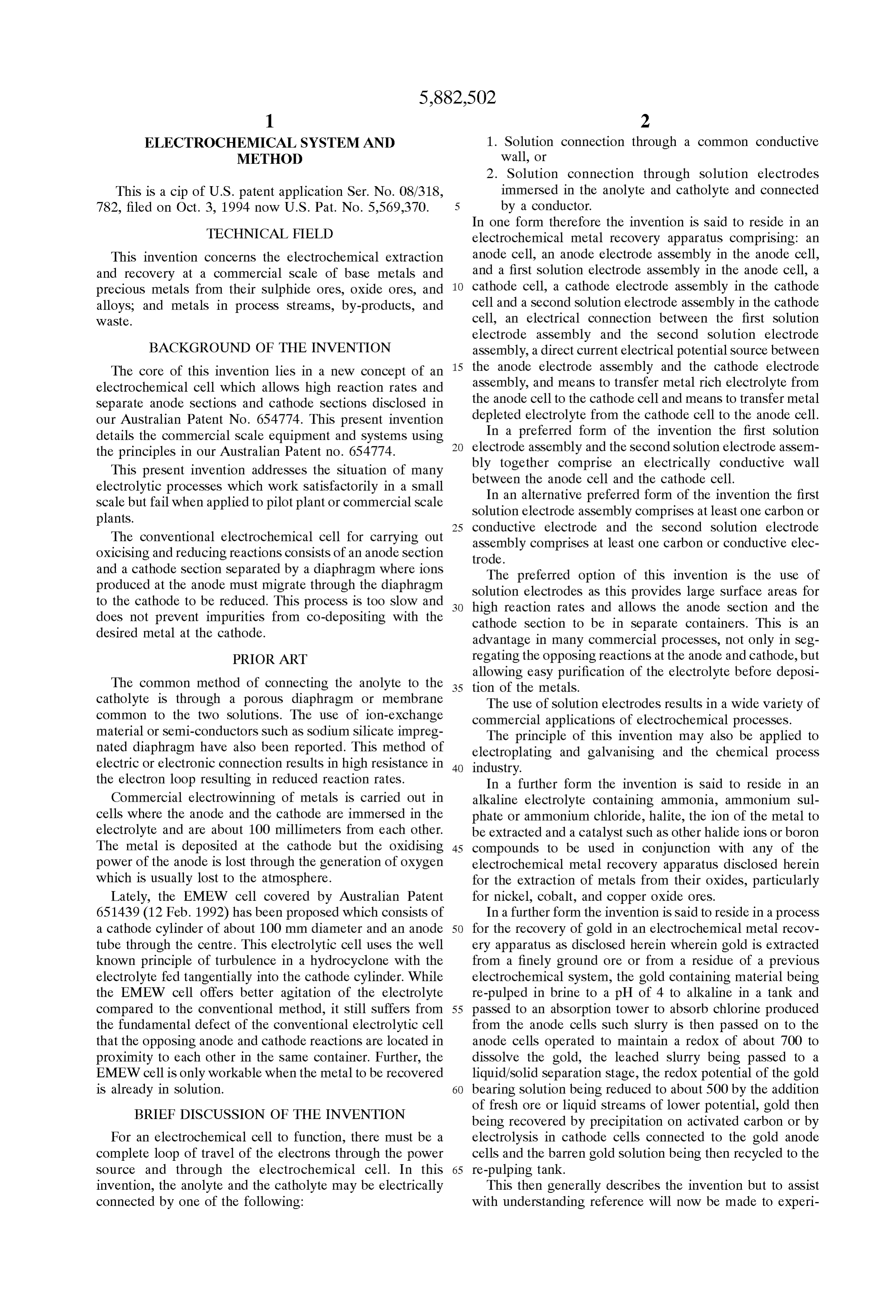
mental investigations of processes according to this inven Using Faraday's law for divalent copper, the current effi tion and preferred embodiments of the invention. ciency based on assay of the electrolyte indicate a current EXPERIMENTAL INVESTIGATIONS efficiency of about 99.95%.
Extraction of Metal from Solution The experiment demonstrated the principle of connecting An experiment was conducted using a cathode cell of 35.7 the catholyte and the anolyte using Solution electrodes mm ID by 230 mm long 316 stainless steel tube with PVC connected by a conductor and that metal is deposited at the cathode. It is also shown that the electrochemical cell of the end caps and eight 6.35 mm OD and one 9.53 mm OD present invention can operate at high current efficiency even carbon rods as Solution electrodes. The anode cell connected to the top of the cathode cell was a 36.8 mm ODx270 mm 1O at very low concentration of metal in the electrolyte. Experiment to Dissolve Copper-Cobalt Sulphide Concen long PVC tube with eight 6.35 mm OD carbon rods as anode trate electrodes and one 9.53 mm OD carbon rod Solution elec trode. The electrolyte was 2.5 liters of demineralised water Limited resources and the unavailability of Small pumps with 49 grams of copper Sulphate and acidified to a pH of to handle hot corrosive slurries made this experiment diffi 2.5. A pump circulated the electrolyte through the cathode 15 Theto anode cult carry out.
cell of the apparatus consisted of a 115 mm cell then to the anode cell at about 9.5 liters per minute. IDx625 mm long polypropylene tube anode fitted with Temperature ranged from 33° to 37° C. seven 19 mm ODx610 mm long half round carbon rods for The first test was carried out to demonstrate the principle the anode and a similar number of Solution electrodes of connecting the catholyte and anolyte using Solution arranged in a circular pattern electrodes connected by a copper wire rather than by elec humidified air was introduced atnextthetobottom each other. Hot through a trical connection occurring through the Solution. polypropylene filter cloth at the rate of 6 liters per minute. The results were:
The cathode cell fitted with a silica tube heater consisted of a two compartment 90 mmx200 mmx230 mm deep poly
CELL AMPERES propylene box with a circulation well and fitted with a glass
CELL AMPERES SOL CURRENT 25 propeller driven by a variable Speed power drill mounted on
CELL VOLTS
SOL ELECTRODES ELECTRODES INCREASE
NOT CONNECTED CONNECTED (TIMES)
a stand. The cathodes were four pieces of 60 mmx200 mm immersed lengthX1.0 mm thick 316 stainless Steel plates.
1.OO O.O1 O.OS 4.0 The solution electrodes were 60 pieces of 6.35 mm OD
carbon rods arranged 10 in line between each of the cathode
plates. A 400 mm diameter polypropylene cone with four 3.OO O.O3 1.50 49.0 Silica tube heaters was used as a thickener between the anode 3.50 O.O4 2.52 62.O cell and the cathode cell. All the equipment was insulated as 4.OO O.OS 3.78 74.6 the operating temperature was 85 to 90 degrees Celsius. 4.50 O.O6 5.59 92.2 The experiment used 474 grams of a 30.4% copper,
5.50 O.O8 8.39 103.9 35 0.096% cobalt Sulphide concentrate. The electrolyte was an 6.OO O.O9 1046 115.2 acidified halite copper Sulphate Solution containing about 15 6.50 O.11 11.92 107.4 grams of copper per liter. The pH was kept below 2.50. During the experiment, the thickener underflow and the
It will be noted that there was a Substantial increase in coil cathode cell overflow were pumped to the anode cell. current when the Solution electrodes were connected. The 40 Leached slurry overflowed from the anode cell to the rate of current increase increased with Voltage but the rate of thickener.
Catholyte
Thickener overflow fed into the cathode cell.
flowed from the constant level tube of the cathode increase diminished after 6.00 volts. These are important cell and was pumped to the anode cell. observations in the development of this concept. Data on the test were as follows: Using the same Set-up and with the Solution electrodes connected with a copper wire current was passed through the 45 cells at 3.3 volts for almost 3 hours. Copper sheet was CELL CATHODE deposited at the cathode and the results were: TIME Hours. CELL Wolts Current ANODE pH pH
Cu in 50 O2:OO 1.10 4.27 2.21 2O3 TIME SOLN COPPER O3:OO 140 4.75 2.29 2.01 MIN- MII- SOLN CELL CELL DEPOSITED O4:OO 18O 7.30 2.32 2.12
UTES grams/L pH AMPERES AMP-HRS Grams
O 3,070 2.32 2.56 O7:OO 2.20 11.98 2.31 2.01 15 2.74 O8.OO 2.67 1155 2.14 1.85 55 O9:OO 2.75 13.37 1.96 1.78
45 3.13 10:OO 2.75 13.82 1.83 1.70 60 3,540 1.64 3.34 11:00 2.75 14.09 1.75 1.67 75 3.49 12:OO 2.75 14.29 1.26 1.21 90 3.66 O1:OO 2.75 14.52 1.43 1.44
135 4.OO During the test, it was observed that the thickener was too 150 3.74 Small for the required pump flow rate and fine Sulphide and
reaction products overflowed into the cathode cell. After the test, it was observed that solids had settled on the slope of 65 the thickener, at the cathode, in the Slurry pump and in the
The weight of copper deposited at the cathode was 11.8 pipes. There was a Substantial amount of Solids which did grams which included copper deposited during the first test. not participate in the reaction.
Page 17
S 6
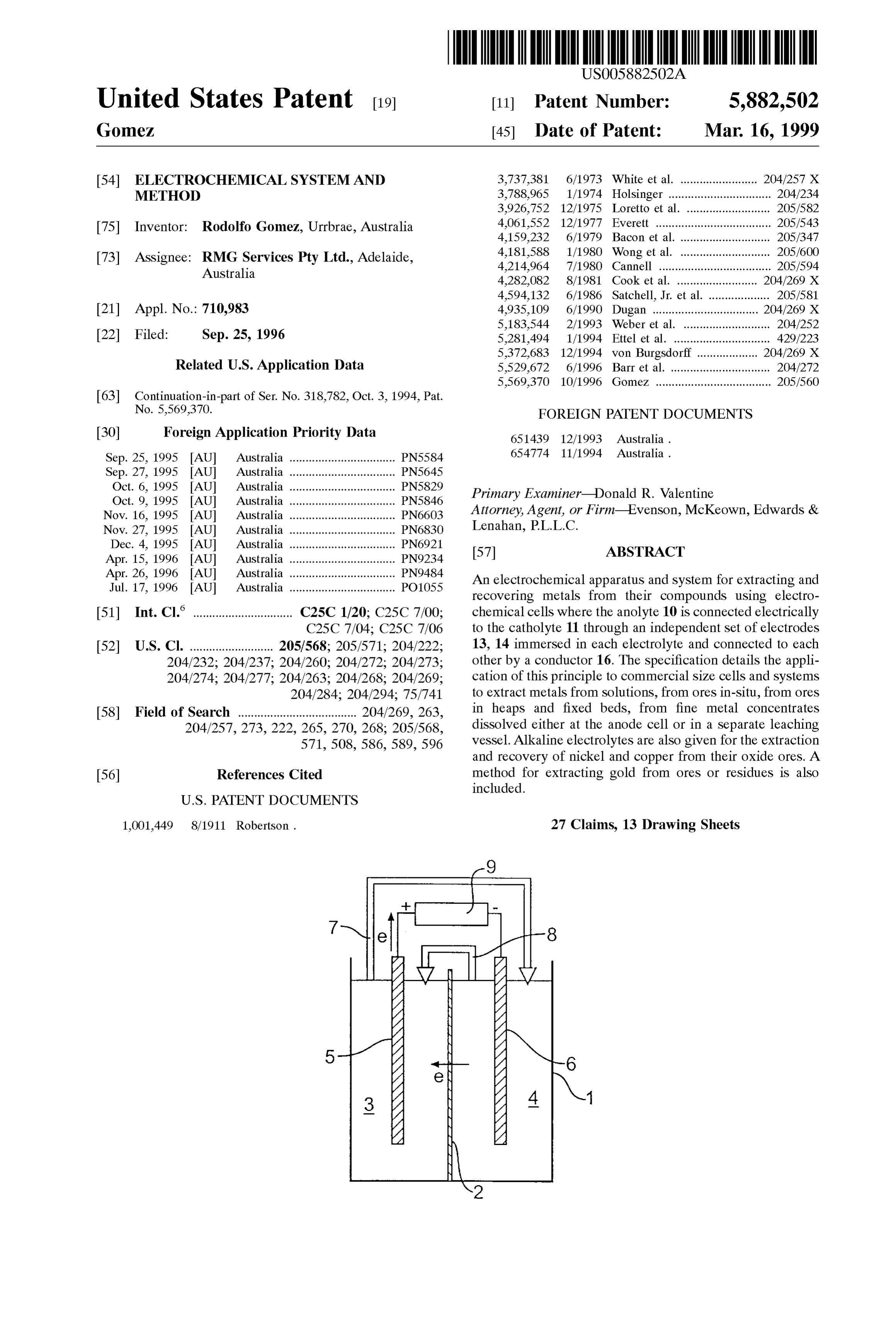
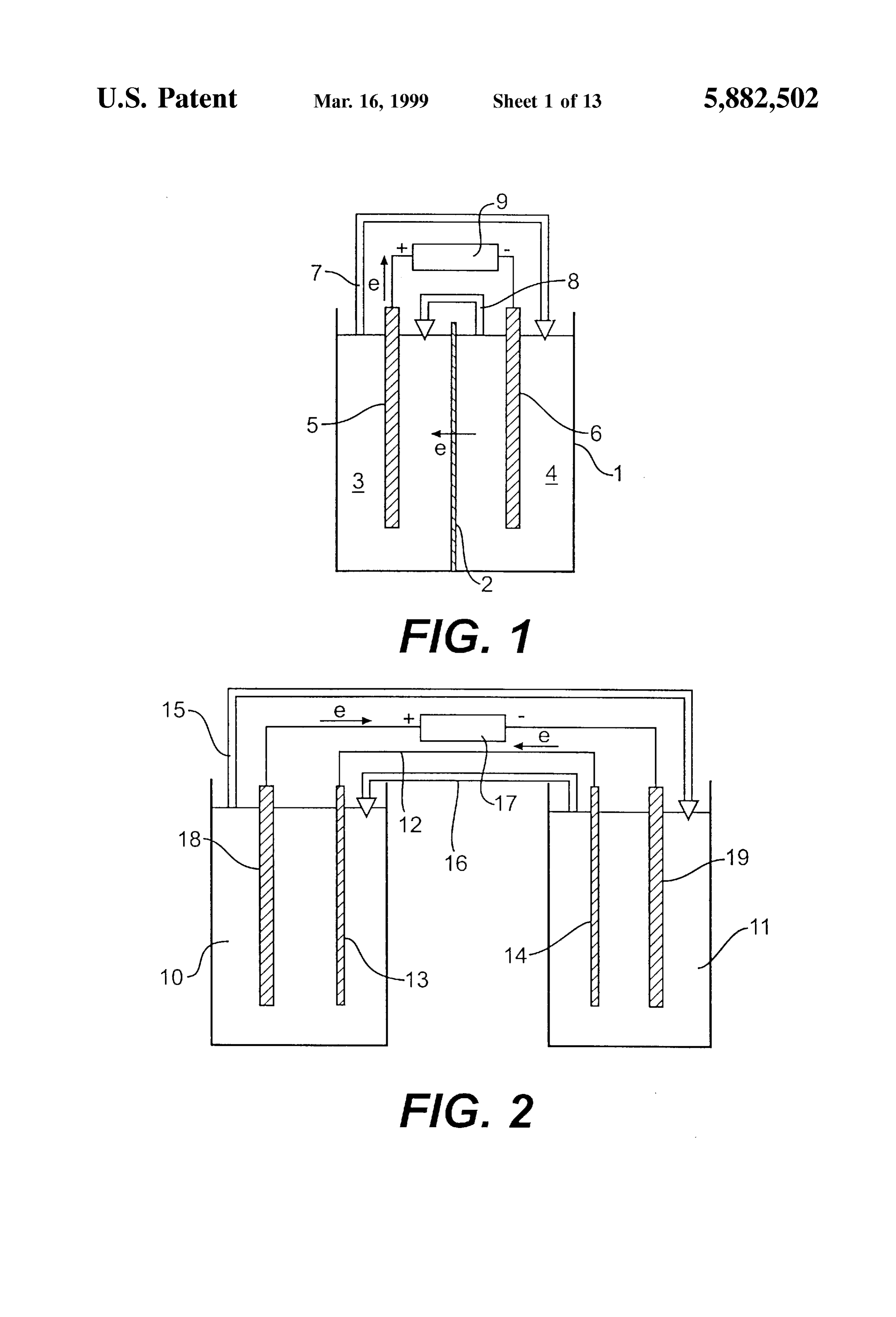
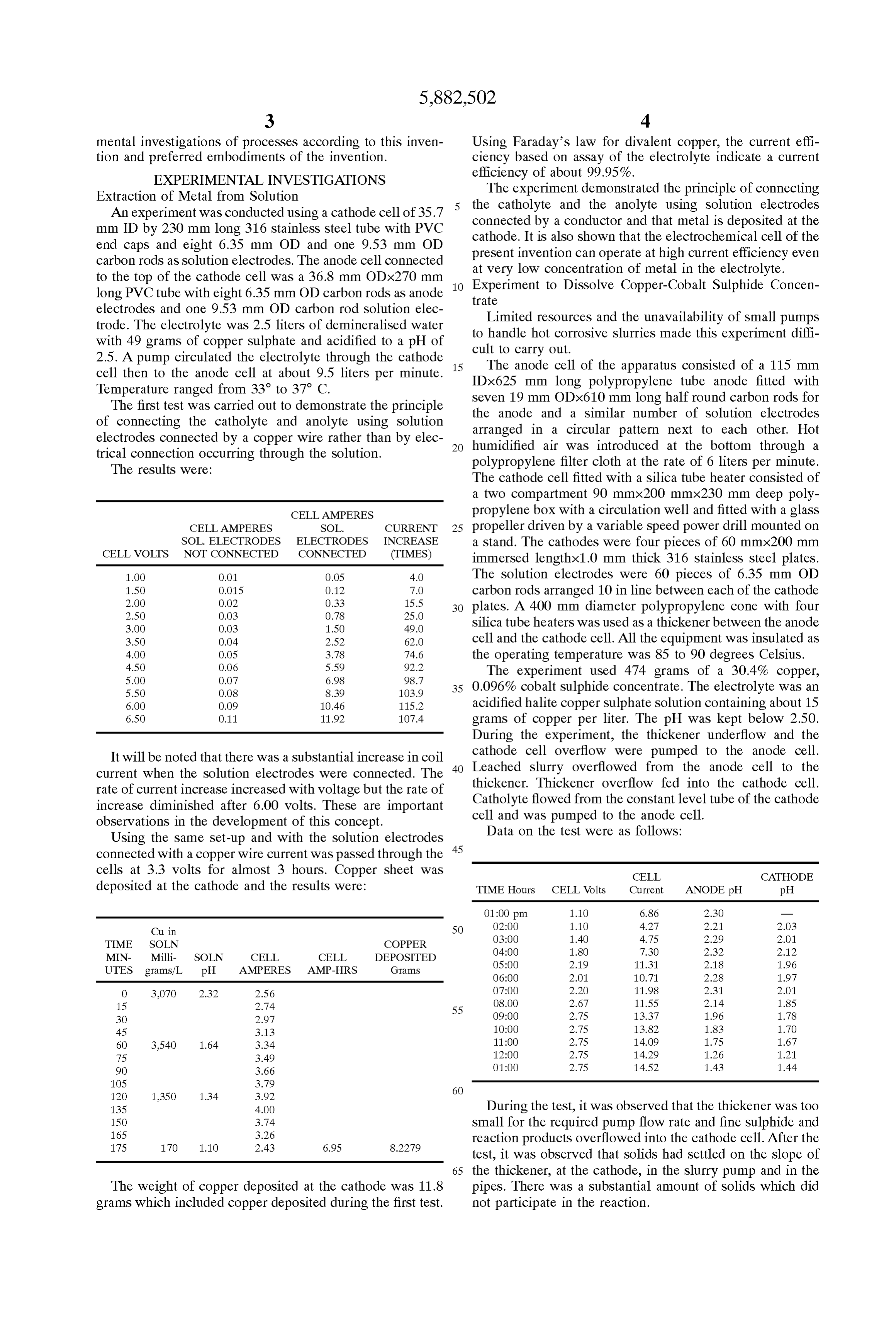
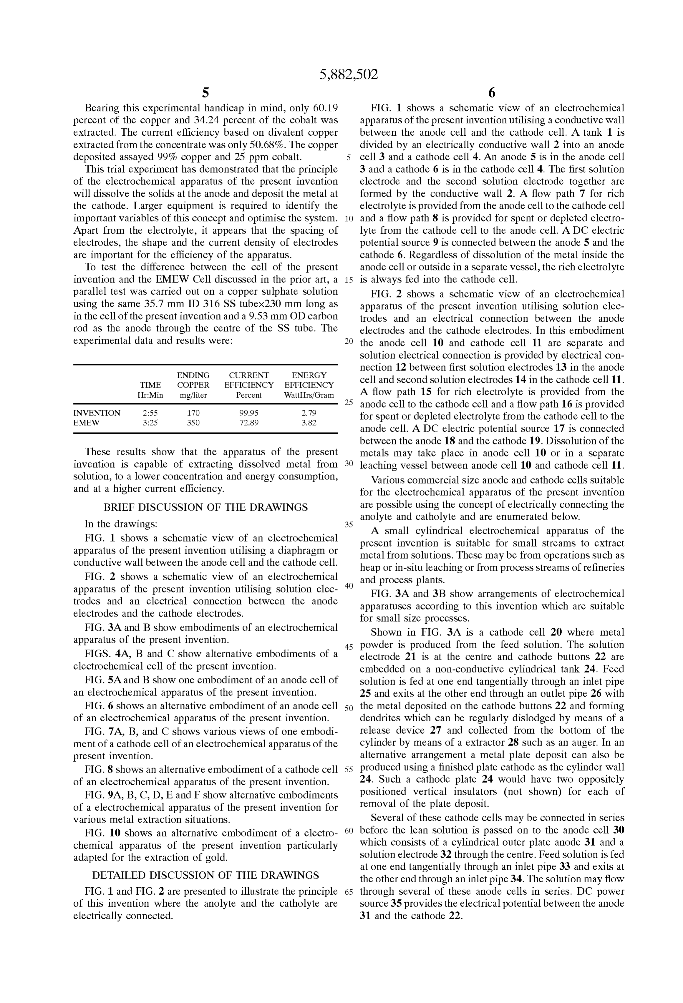
Bearing this experimental handicap in mind, only 60.19 FIG. 1 shows a schematic view of an electrochemical percent of the copper and 34.24 percent of the cobalt was apparatus of the present invention utilising a conductive wall extracted. The current efficiency based on divalent copper between the anode cell and the cathode cell. A tank 1 is extracted from the concentrate was only 50.68%. The copper divided by an electrically conductive wall 2 into an anode deposited assayed 99% copper and 25 ppm cobalt. cell 3 and a cathode cell 4. An anode 5 is in the anode cell This trial experiment has demonstrated that the principle 3 and a cathode 6 is in the cathode cell 4. The first Solution of the electrochemical apparatus of the present invention electrode and the Second Solution electrode together are will dissolve the solids at the anode and deposit the metal at formed by the conductive wall 2. A flow path 7 for rich the cathode. Larger equipment is required to identify the electrolyte is provided from the anode cell to the cathode cell important variables of this concept and optimise the System. and a flow path 8 is provided for spent or depleted electro Apart from the electrolyte, it appears that the Spacing of lyte from the cathode cell to the anode cell. A DC electric electrodes, the shape and the current density of electrodes potential source 9 is connected between the anode 5 and the are important for the efficiency of the apparatus. cathode 6. Regardless of dissolution of the metal inside the To test the difference between the cell of the present anode cell or outside in a separate vessel, the rich electrolyte invention and the EMEW Cell discussed in the prior art, a 15 is always fed into the cathode cell. parallel test was carried out on a copper Sulphate Solution FIG. 2 shows a schematic view of an electrochemical using the same 35.7 mm ID 316 SS tubex230 mm long as apparatus of the present invention utilising Solution elec in the cell of the present invention and a 9.53 mm OD carbon trodes and an electrical connection between the anode rod as the anode through the centre of the SS tube. The electrodes and the cathode electrodes. In this embodiment experimental data and results were: the anode cell 10 and cathode cell 11 are separate and Solution electrical connection is provided by electrical con nection 12 between first Solution electrodes 13 in the anode
ENDING CURRENT ENERGY
TIME COPPER EFFICIENCY EFFICIENCY
cell and second Solution electrodes 14 in the cathode cell 11.
Hr:Min mg/liter Percent WattHrs/Gram A flow path 15 for rich electrolyte is provided from the 25 anode cell to the cathode cell and a flow path 16 is provided
for spent or depleted electrolyte from the cathode cell to the anode cell. A DC electric potential source 17 is connected between the anode 18 and the cathode 19. Dissolution of the
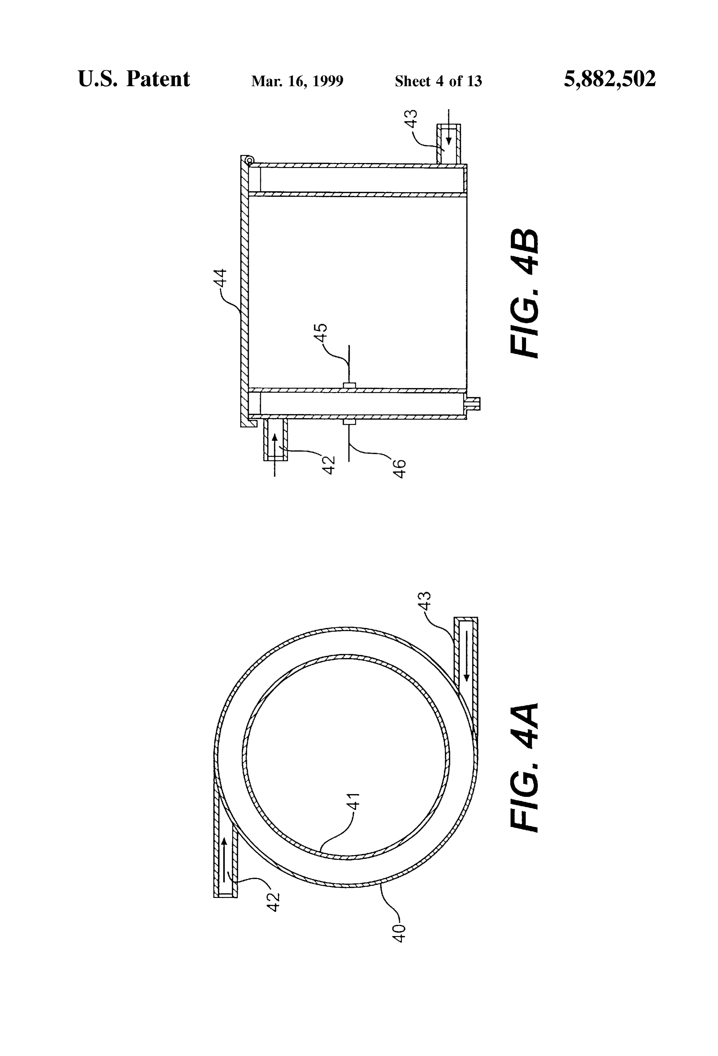
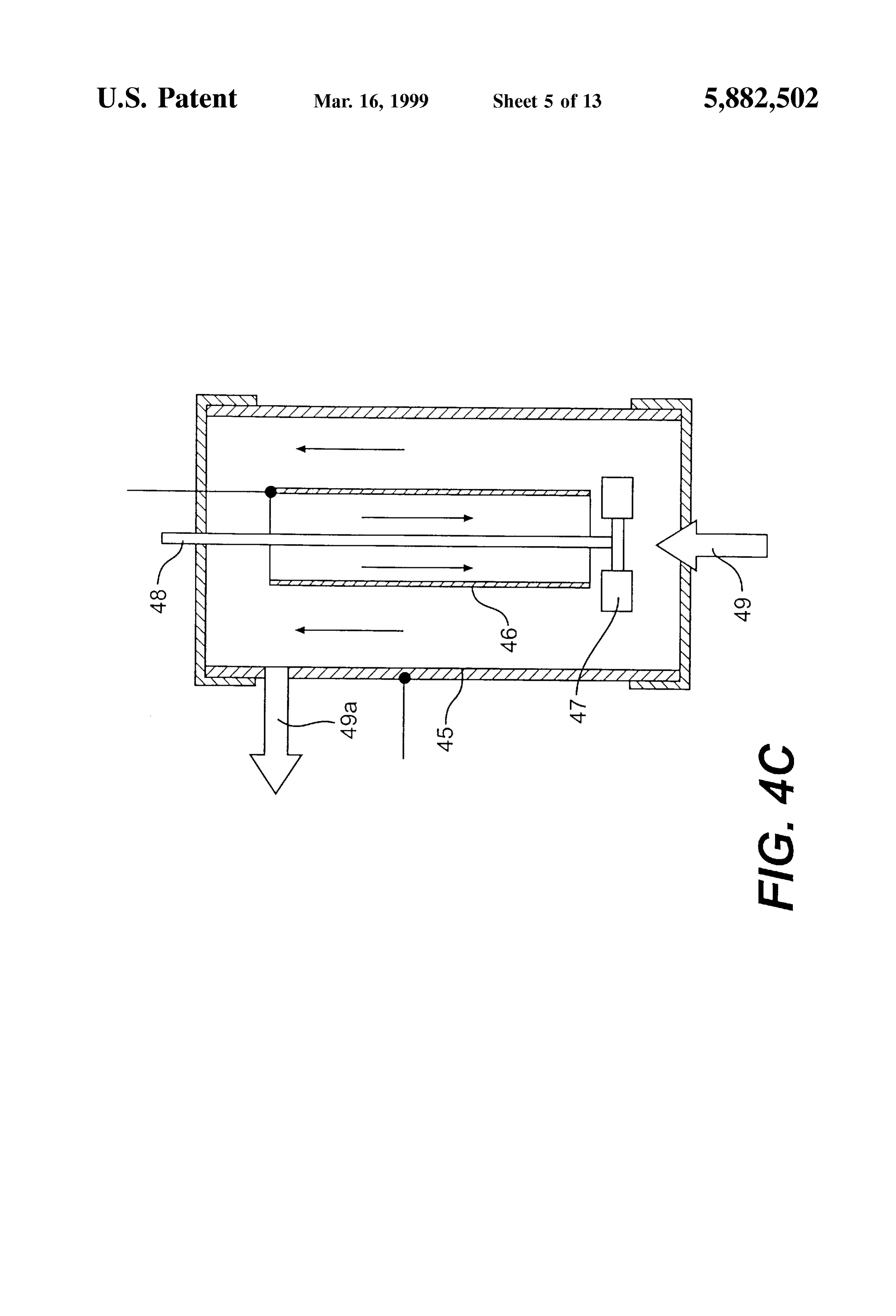
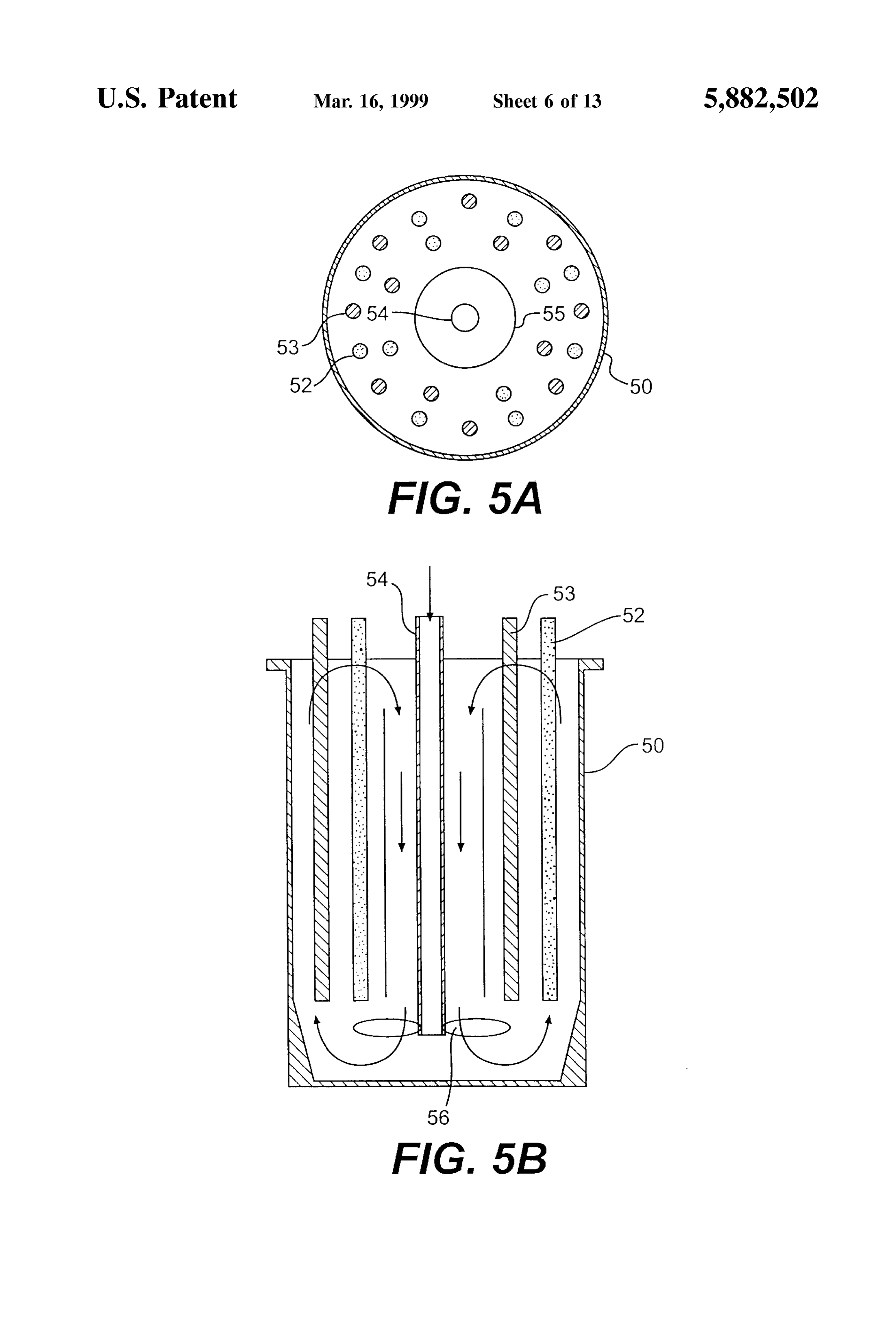
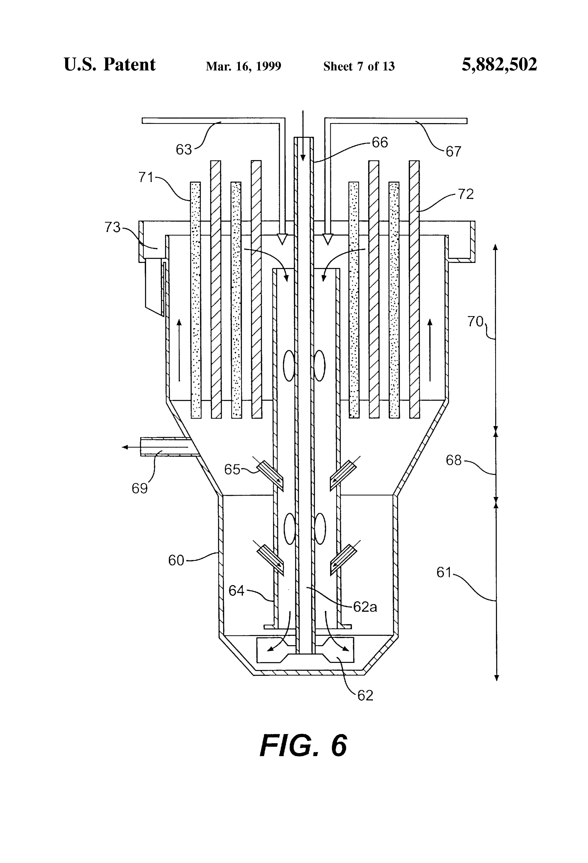
These results show that the apparatus of the present metals may take place in anode cell 10 or in a Separate invention is capable of extracting dissolved metal from leaching vessel between anode cell 10 and cathode cell 11. Solution, to a lower concentration and energy consumption, Various commercial size anode and cathode cells Suitable and at a higher current efficiency. for the electrochemical apparatus of the present invention BRIEF DISCUSSION OF THE DRAWINGS are possible using the concept of electrically connecting the
anolyte and catholyte and are enumerated below.
FIG. 1 shows a schematic view of an electrochemical
A Small cylindrical electrochemical apparatus of the present invention apparatus of the present invention utilising a diaphragm or metal from Solutions. is Suitable for Small Streams to extract conductive wall between the anode cell and the cathode cell. These may be from operations Such as heap or in-situ leaching or from proceSS Streams of refineries
FIG. 2 shows a schematic view of an electrochemical and process plants.
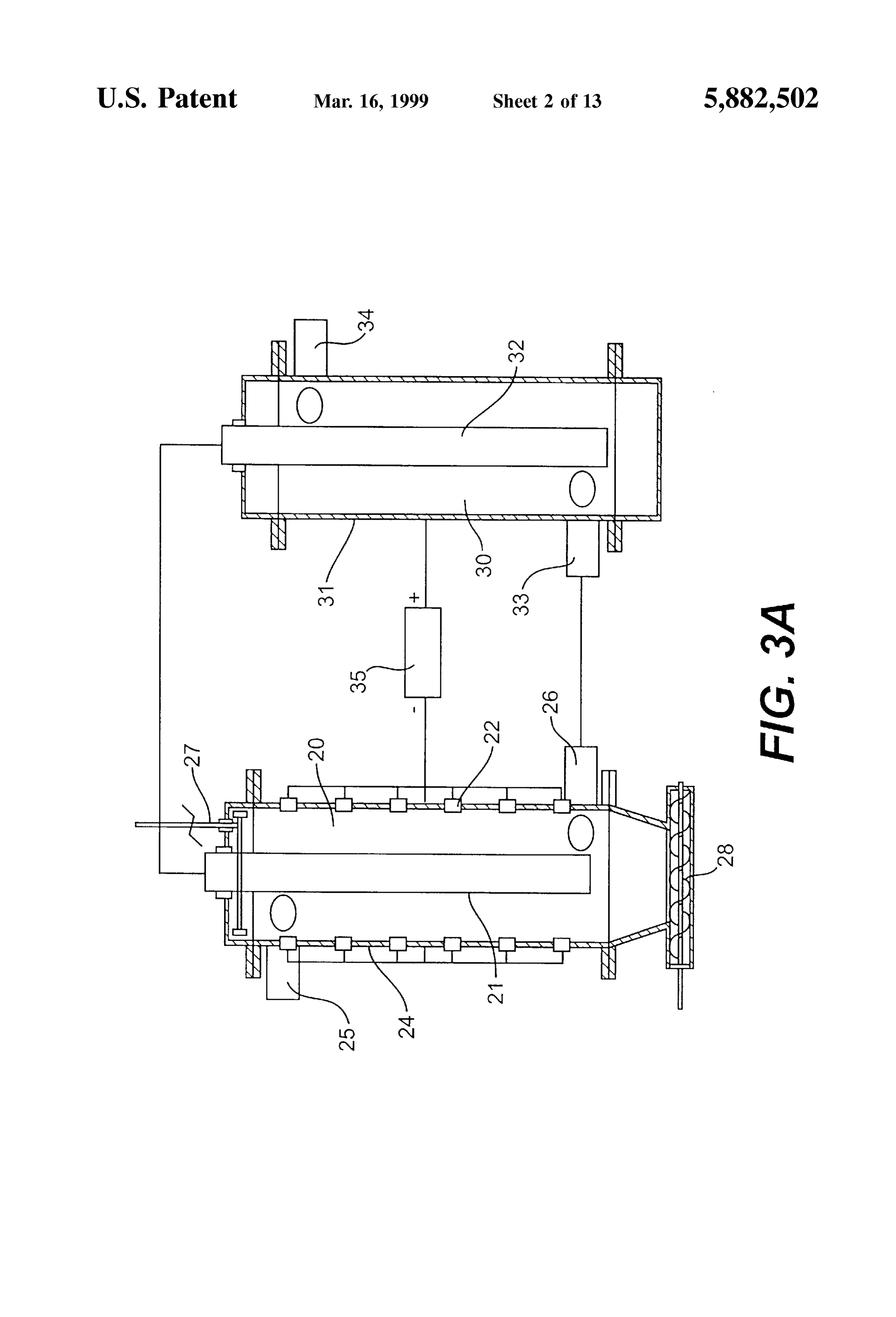
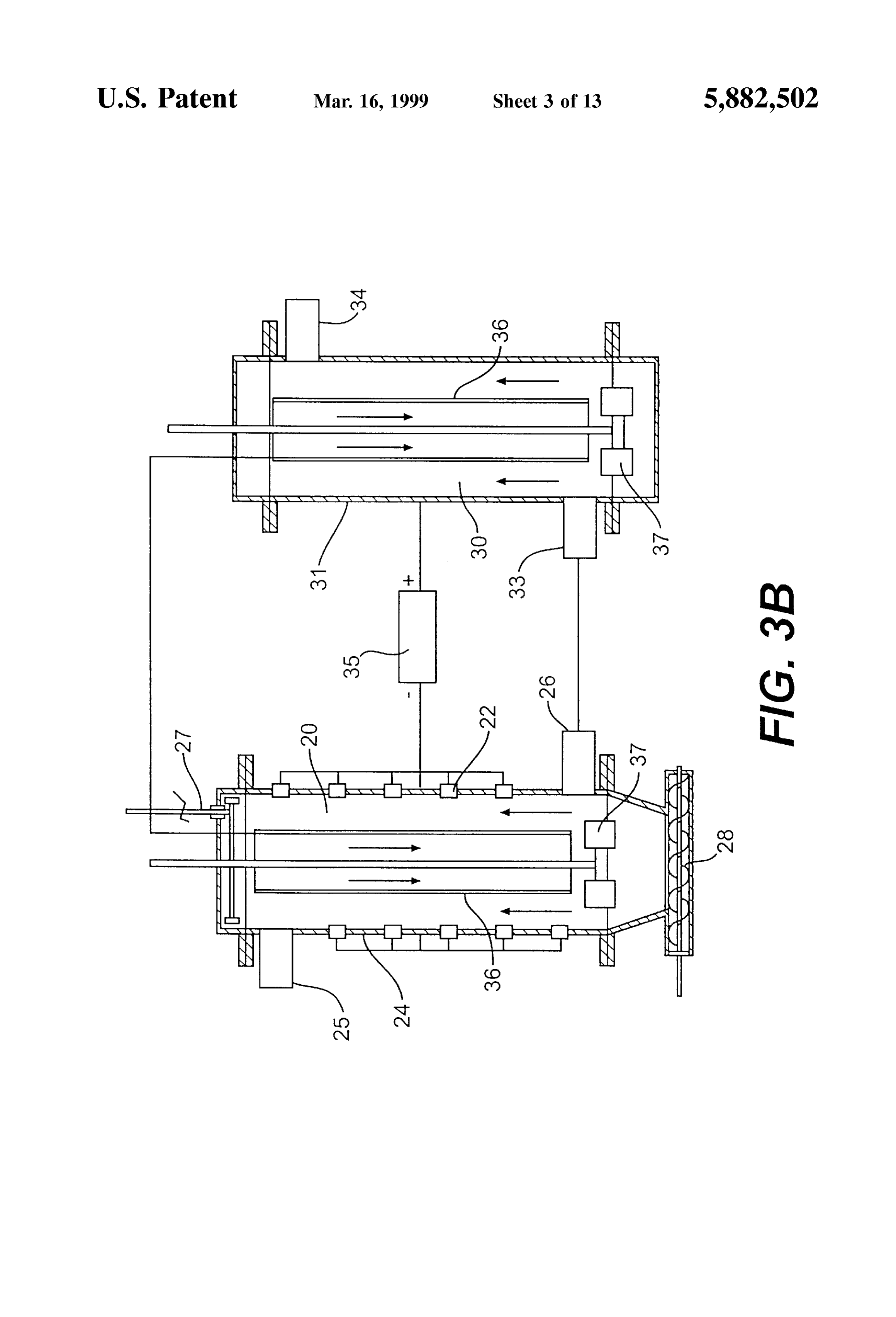
apparatus of the present invention utilising Solution elec 40 FIG. 3A and 3B show arrangements of electrochemical trodes and an electrical connection between the anode electrodes and the cathode electrodes.
apparatuses according to this invention which are Suitable for Small size processes.
FIG. 3A and B show embodiments of an electrochemical Shown in FIG. 3A is a cathode cell 20 where metal apparatus of the present invention. 45 powder is produced from the feed solution. The solution FIGS. 4A, B and C show alternative embodiments of a electrode 21 is at the centre and cathode buttons 22 are electrochemical cell of the present invention. embedded on a non-conductive cylindrical tank 24. Feed FIG. 5A and B show one embodiment of an anode cell of Solution is fed at one end tangentially through an inlet pipe an electrochemical apparatus of the present invention. 25 and exits at the other end through an outlet pipe 26 with FIG. 6 shows an alternative embodiment of an anode cell 50 the metal deposited on the cathode buttons 22 and forming of an electrochemical apparatus of the present invention. dendrites which can be regularly dislodged by means of a FIG. 7A, B, and C shows various views of one embodi release device 27 and collected from the bottom of the ment of a cathode cell of an electrochemical apparatus of the cylinder by means of a extractor 28 Such as an auger. In an present invention. alternative arrangement a metal plate deposit can also be FIG. 8 shows an alternative embodiment of a cathode cell 55 produced using a finished plate cathode as the cylinder wall of an electrochemical apparatus of the present invention. 24. Such a cathode plate 24 would have two oppositely FIG. 9A, B, C, D, E and F show alternative embodiments positioned vertical insulators (not shown) for each of of a electrochemical apparatus of the present invention for removal of the plate deposit. various metal extraction situations. Several of these cathode cells may be connected in Series FIG. 10 shows an alternative embodiment of a electro 60 before the lean solution is passed on to the anode cell 30 chemical apparatus of the present invention particularly which consists of a cylindrical outer plate anode 31 and a adapted for the extraction of gold. solution electrode 32 through the centre. Feed solution is fed
DETAILED DISCUSSION OF THE DRAWINGS
at one end tangentially through an inlet pipe 33 and exits at the other end through an inlet pipe 34. The solution may flow
FIG. 1 and FIG. 2 are presented to illustrate the principle 65 through Several of these anode cells in Series. DC power of this invention where the anolyte and the catholyte are Source 35 provides the electrical potential between the anode electrically connected. 31 and the cathode 22.
Page 18
Sufficient agitation from tangential entry is generally desired or harmful. FIG. 6 shows an anode cell where the limited to small diameter cylinders. This is a limitation of the Solids are not in contact with the electrodes. The anodes act tangential entry concept and becomes exacerbated when on the Solution and the reaction occurs between the Solids electrolyte flow rates are Small. and the Solution.
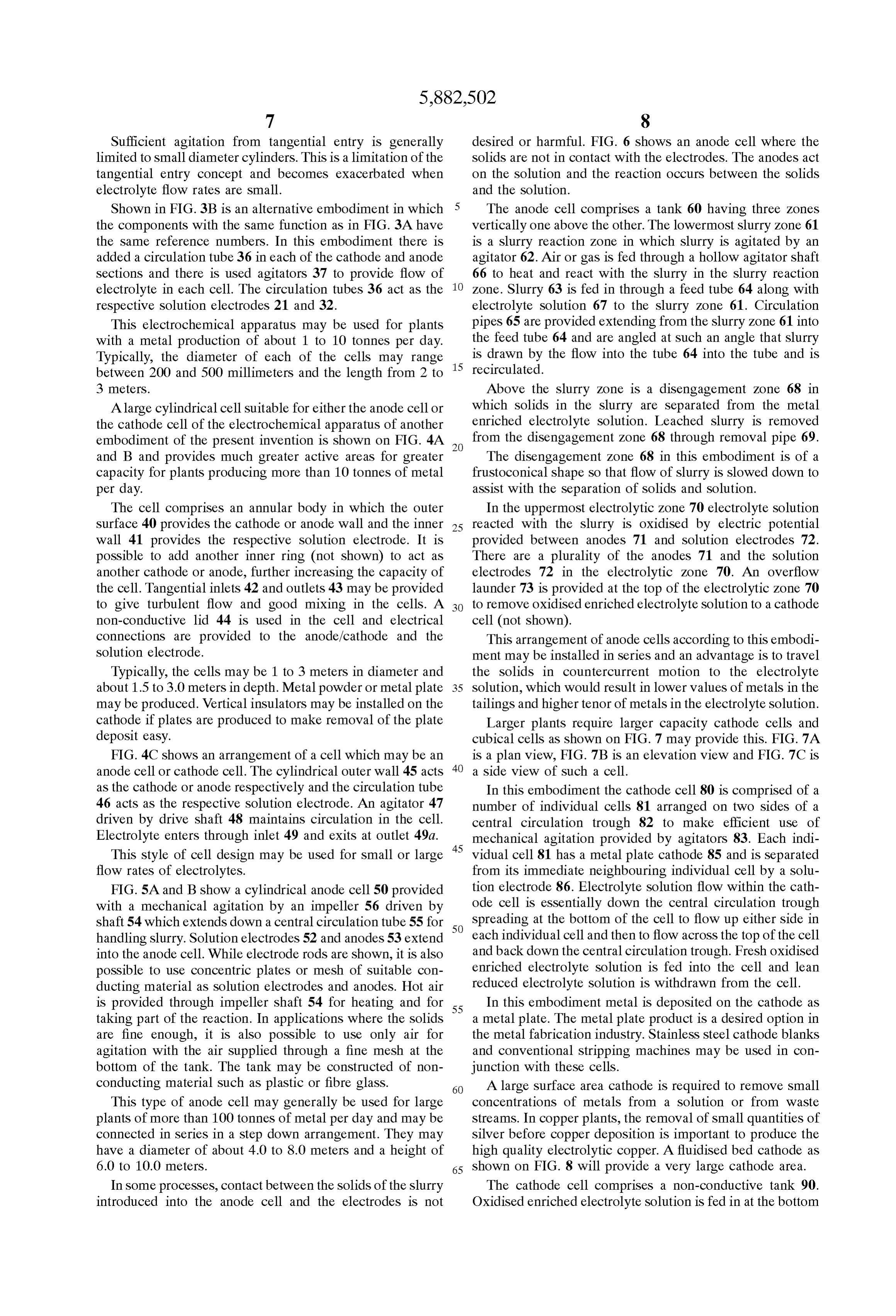
Shown in FIG. 3B is an alternative embodiment in which 5 The anode cell comprises a tank 60 having three Zones the components with the same function as in FIG. 3A have vertically one above the other. The lowermost slurry Zone 61 the Same reference numbers. In this embodiment there is is a slurry reaction Zone in which slurry is agitated by an added a circulation tube 36 in each of the cathode and anode agitator 62. Air or gas is fed through a hollow agitator Shaft sections and there is used agitators 37 to provide flow of 66 to heat and react with the slurry in the slurry reaction electrolyte in each cell. The circulation tubes 36 act as the Zone. Slurry 63 is fed in through a feed tube 64 along with respective solution electrodes 21 and 32. electrolyte solution 67 to the slurry Zone 61. Circulation This electrochemical apparatus may be used for plants pipes 65 are provided extending from the slurry Zone 61 into with a metal production of about 1 to 10 tonnes per day. the feed tube 64 and are angled at Such an angle that slurry Typically, the diameter of each of the cells may range is drawn by the flow into the tube 64 into the tube and is between 200 and 500 millimeters and the length from 2 to 15 recirculated.
3 meters. Above the Slurry Zone is a disengagement Zone 68 in A large cylindrical cell Suitable for either the anode cell or which Solids in the Slurry are separated from the metal the cathode cell of the electrochemical apparatus of another enriched electrolyte Solution. Leached slurry is removed embodiment of the present invention is shown on FIG. 4A from the disengagement Zone 68 through removal pipe 69. and B and provides much greater active areas for greater The disengagement Zone 68 in this embodiment is of a capacity for plants producing more than 10 tonnes of metal frustoconical shape so that flow of slurry is slowed down to per day. assist with the Separation of Solids and Solution. The cell comprises an annular body in which the outer In the uppermost electrolytic Zone 70 electrolyte solution surface 40 provides the cathode or anode wall and the inner 25 reacted with the Slurry is oxidised by electric potential wall 41 provides the respective solution electrode. It is provided between anodes 71 and solution electrodes 72. possible to add another inner ring (not shown) to act as There are a plurality of the anodes 71 and the solution another cathode or anode, further increasing the capacity of electrodes 72 in the electrolytic Zone 70. An overflow the cell. Tangential inlets 42 and outlets 43 may be provided launder 73 is provided at the top of the electrolytic Zone 70 to give turbulent flow and good mixing in the cells. A to remove oxidised enriched electrolyte Solution to a cathode non-conductive lid 44 is used in the cell and electrical cell (not shown).
connections are provided to the anode/cathode and the This arrangement of anode cells according to this embodi Solution electrode. ment may be installed in Series and an advantage is to travel Typically, the cells may be 1 to 3 meters in diameter and the Solids in countercurrent motion to the electrolyte about 1.5 to 3.0 meters in depth. Metal powder or metal plate 35 Solution, which would result in lower values of metals in the may be produced. Vertical insulators may be installed on the tailings and higher tenor of metals in the electrolyte Solution. cathode if plates are produced to make removal of the plate Larger plants require larger capacity cathode cells and deposit easy. cubical cells as shown on FIG.7 may provide this. FIG. 7A FIG. 4C shows an arrangement of a cell which may be an is a plan view, FIG. 7B is an elevation view and FIG. 7C is anode cell or cathode cell. The cylindrical outer wall 45 acts 40 a side view of Such a cell.
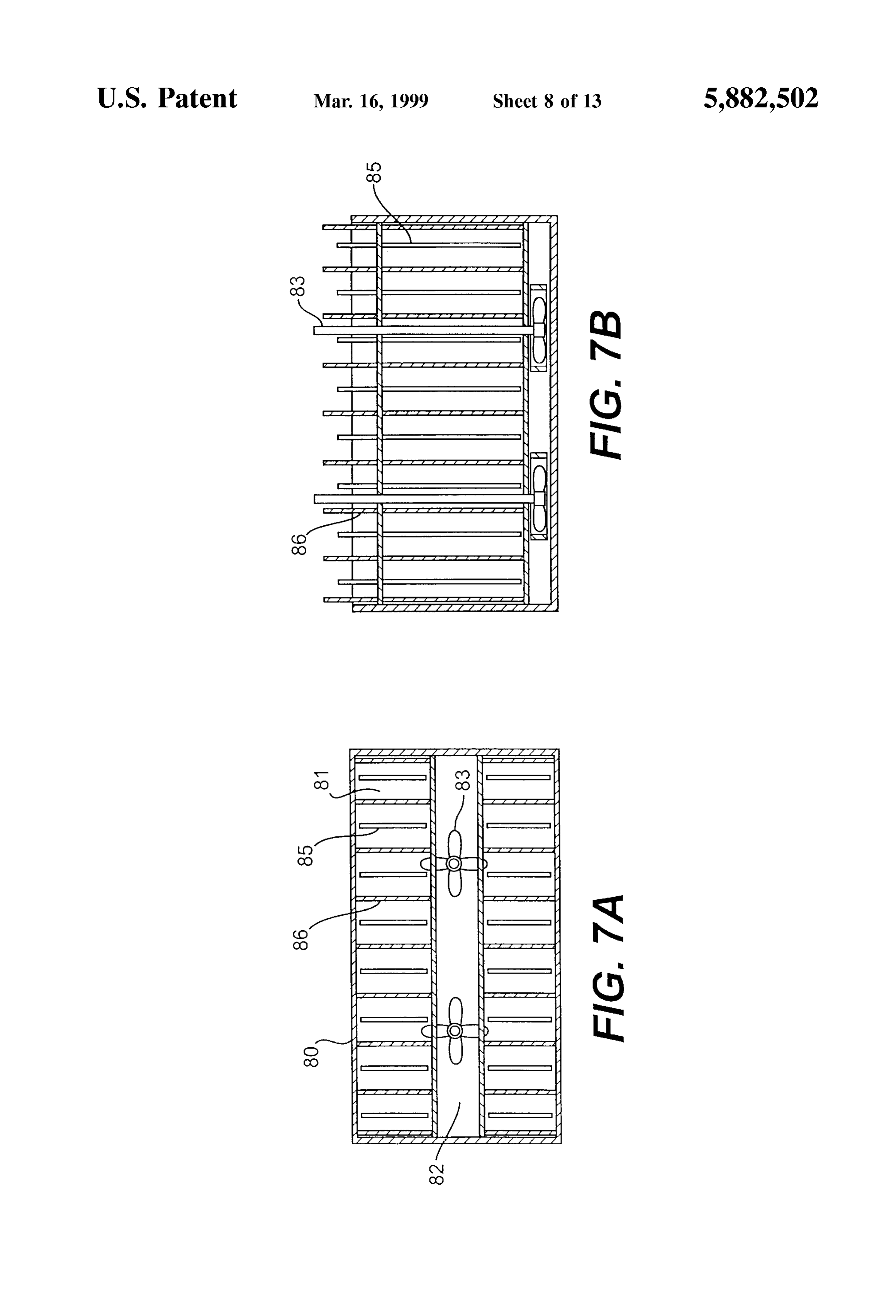
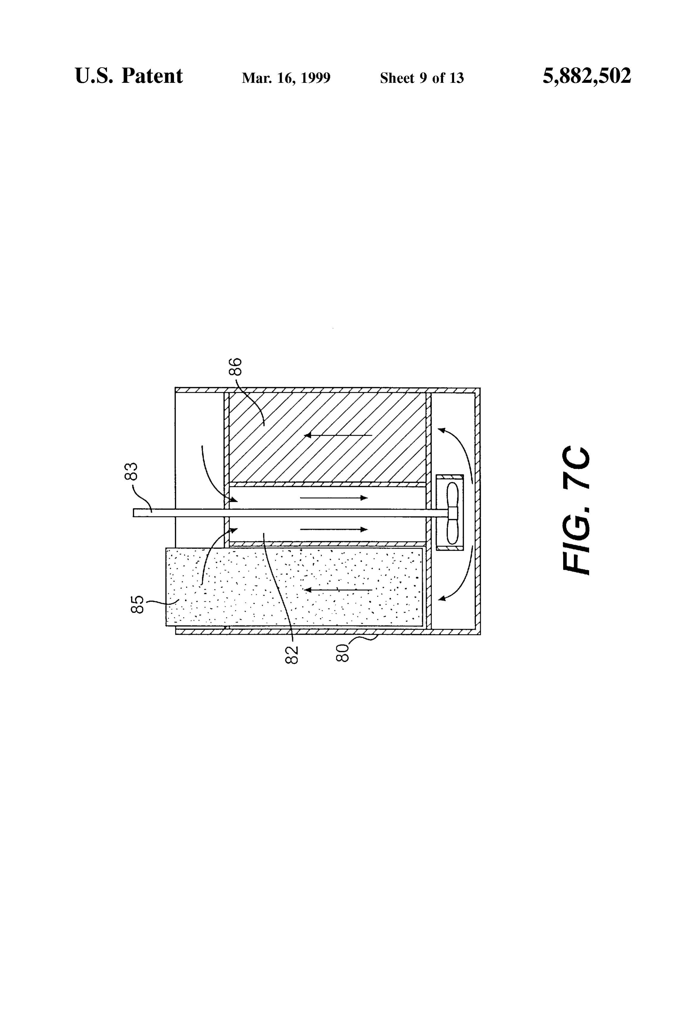
as the cathode or anode respectively and the circulation tube In this embodiment the cathode cell 80 is comprised of a 46 acts as the respective Solution electrode. An agitator 47 number of individual cells 81 arranged on two sides of a driven by drive shaft 48 maintains circulation in the cell. central circulation trough 82 to make efficient use of Electrolyte enters through inlet 49 and exits at outlet 49a. mechanical agitation provided by agitators 83. Each indi This style of cell design may be used for Small or large 45 vidual cell 81 has a metal plate cathode 85 and is separated flow rates of electrolytes. from its immediate neighbouring individual cell by a Solu FIG. 5A and B show a cylindrical anode cell 50 provided tion electrode 86. Electrolyte solution flow within the cath with a mechanical agitation by an impeller 56 driven by ode cell is essentially down the central circulation trough shaft 54 which extends down a central circulation tube 55 for 50 Spreading at the bottom of the cell to flow up either side in handling slurry. Solution electrodes 52 and anodes 53 extend each individual cell and then to flow across the top of the cell into the anode cell. While electrode rods are shown, it is also and back down the central circulation trough. Fresh oxidised possible to use concentric plates or mesh of Suitable con enriched electrolyte Solution is fed into the cell and lean ducting material as Solution electrodes and anodes. Hot air reduced electrolyte solution is withdrawn from the cell. is provided through impeller shaft 54 for heating and for 55 In this embodiment metal is deposited on the cathode as taking part of the reaction. In applications where the Solids a metal plate. The metal plate product is a desired option in are fine enough, it is also possible to use only air for the metal fabrication industry. Stainless steel cathode blanks agitation with the air Supplied through a fine mesh at the and conventional Stripping machines may be used in con bottom of the tank. The tank may be constructed of non junction with these cells.
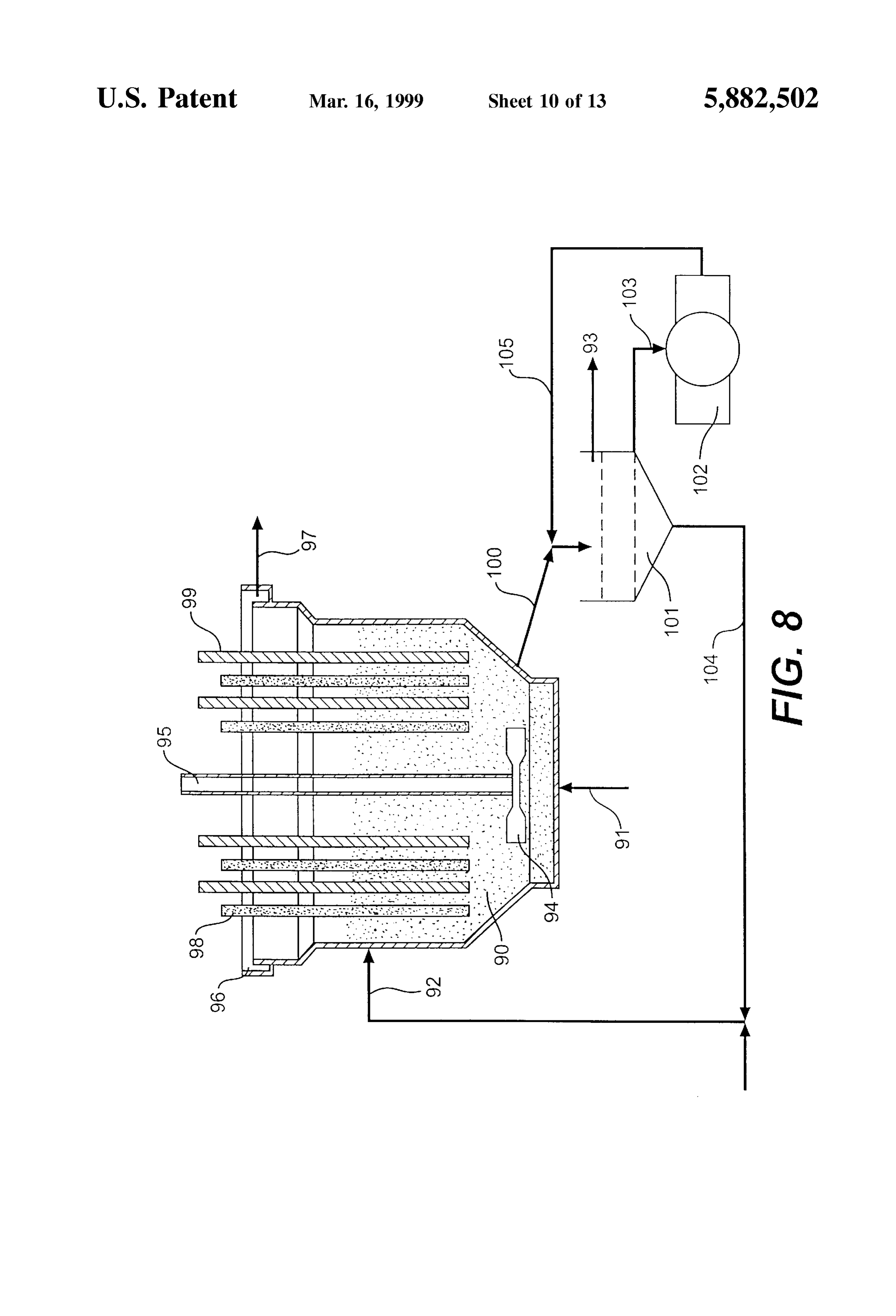
conducting material Such as plastic or fibre glass. 60 A large Surface area cathode is required to remove Small This type of anode cell may generally be used for large concentrations of metals from a Solution or from waste plants of more than 100 tonnes of metal per day and may be Streams. In copper plants, the removal of Small quantities of connected in Series in a Step down arrangement. They may Silver before copper deposition is important to produce the have a diameter of about 4.0 to 8.0 meters and a height of high quality electrolytic copper. A fluidised bed cathode as 6.0 to 10.0 meterS. 65 shown on FIG. 8 will provide a very large cathode area. In Some processes, contact between the Solids of the Slurry The cathode cell comprises a non-conductive tank 90. introduced into the anode cell and the electrodes is not Oxidised enriched electrolyte solution is fed in at the bottom
Page 19
of the tank 90 through pipe 91 and fine metal powder is fed These alkaline electrolytes are desirable because the alka in at the side of the tank 90 through line 92. The metal line component is regenerated at the cathode So that theo powder is kept in Suspension by an agitator 94 driven by retically the reagent consumption is Zero. The alkaline shaft 95. Depleted electrolyte solution is removed in line 97 electrolyte also removes impurities Such as iron and bismuth from an overflow launder 96 around the top of the tank 90. from the Solution.
Cathodes 98 and Solution electrodes 99 extend down into the The electrochemical apparatus of the present invention fluidised metal powder. may be used to extract metal from Solutions or from metal Metal powder is removed from the tank in line 100 and ores and compounds in commercial Scale in a range of screened in a screen 101. Coarse metal product 93 is Situations.
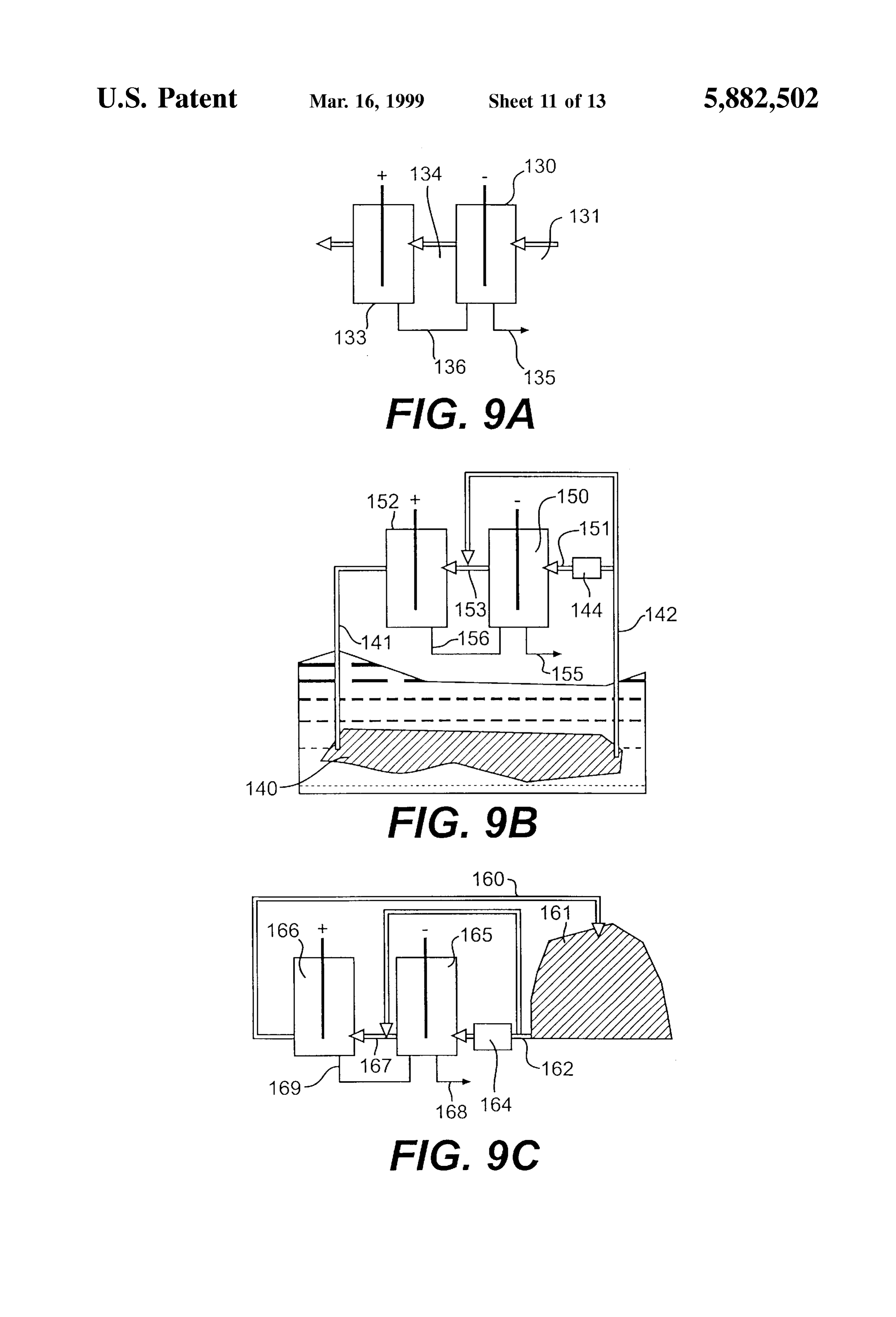
removed from the top of the screen 101 as product, medium These are diagrammatically shown on FIG. 9A to FIG.9F. size powder is fed to a crusher 102 by line 103 and fines are The cells used may be any of those described in FIG. 3 to recycled to the cathode tank. Crushed product from the FIG. 8 using the solution electrodes. crusher 102 is returned on line 105 to the Screen 101 for FIG. 9A shows the removal of metal ions from Solution. re-Screening. This is the Simplest System where metal ions are to be In another embodiment of this fluidised bed, the lower 15 removed from a liquid Stream Such as from waste Streams portion of tank 90 containing the fluidised metal powder from a process plant or from mine liquors containing metals may be a conductor and act as the cathode with only the Such A as copper.
Solution with metal ions in it is fed into a cathode cell solution electrodes 99 extending into the fluidised bed.
In practice, several fluidised bed cathodes of this embodi transferred to the 131 130 through line and the metal depleted solution is then anode cell 133 by line 134 while the metal ment may operate in Series and be Serviced by a single deposit is removed through line 135. A solution electrical screen 101 and crusher 102 for the metal product. connection 136 is provided between the cathode cell 130 and ELECTROLYTES the anode cell 133.
Several types of electrolyte may be used with the elec 25 cathode If a large area of the cathode is required, the fluidised bed trochemical apparatus of the present invention. These may cell may be used.
be acqueous, organic or Semi-organic, acidic or alkaline. FIG. 9B shows the recovery of metals from ores in situ. Some of these Solutions are: Often due to environmental or economic grounds, the only way to extract metals from a low grade or deep deposit is by 1. Aqueous acidified metal Sulphate with or without ferric leaching in situ as shown on FIG. 10B. ions Regenerated leach Solution is passed underground 2. Acidified Sodium chloride Solution with metal ions and through line 141 and percolated through a broken under ferric ions. ground orebody 140 and the rich solution is brought to the 3. Electrolyte similar to item 2 above but with another Surface through line 142 and purified in purification stage halide Such as bromine to form a more powerful 144 if required such as by pH control, Solvent extraction or oxidant compound of bromine and chlorine. 35 cementation. Some of the solution 142 may be by-passed to 4. Alkaline electrolyte with the cyanide complex, princi the anode cell to maintain the required metal ion concen pally for the extraction of gold and Silver. tration in 141.
Our laboratory experimental work indicates that acid The rich Solution with metal ions in it is fed into a cathode electrolytes are not ideal for oxide ores Such as laterite ores cell 150 through line 151 and the metal depleted solution is containing nickel oxide. The acid consumption to maintain 40 then transferred to the anode cell 152 by line 153 while the the proper pH of the electrolyte becomes large and proceSS metal deposit is removed through line 155. A solution control becomes difficult. electrical connection 156 is provided between the cathode The following alkaline electrolyte is included in this cell 150 and the anode cell 152.
invention to be used for some Sulphide ores but is more for Metal in Solution is recovered at the cathode where acid use with oxide ores of nickel and copper: 45 is produced in acid electrolyte or ammonia if ammonia 1. Ammonia-ammonium Sulphate with halite and the electrolyte is used or cyanide ions if alkaline cyanide metal ion, electrolyte is used. The reduced solution is fed to the anode 2. Ammonia-ammonium chloride with halite and the where active ions Such as ferrous and cuprous ions (if metal ion. present) are oxidised, thereby regenerating the active leach These alkaline electrolytes may also contain catalysts 50 ingThis agents.
System offers an important advantage in leaching low
Such as boron compounds or other halides Such as bromine. grade
Some reactions Such as in the extraction of precious metals more primary ores copper in situ. These deposits usually contain copper Sulphide Such as chalcopyrite than may require oxygen at the anode.
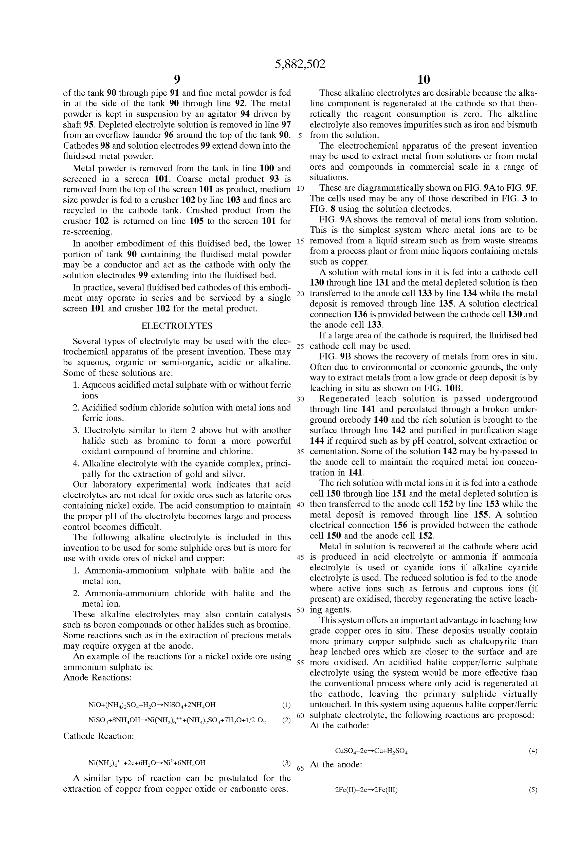
An example of the reactions for a nickel oxide ore using 55 heap leached ores which are closer to the Surface and are more oxidised. An acidified halite copper/ferric Sulphate ammonium Sulphate is: electrolyte using the System would be more effective than Anode Reactions:
the conventional proceSS where only acid is regenerated at the cathode, leaving the primary Sulphide virtually untouched. In this System using aqueous halite copper/ferric 60 Sulphate electrolyte, the following reactions are proposed:
At the cathode:
Cathode Reaction:
65 At the anode:
A Similar type of reaction can be postulated for the extraction of copper from copper oxide or carbonate ores.
Page 20
between the anode cell and the cathode cell may include liquid/solid Separation using thickenerS and filters, or filters
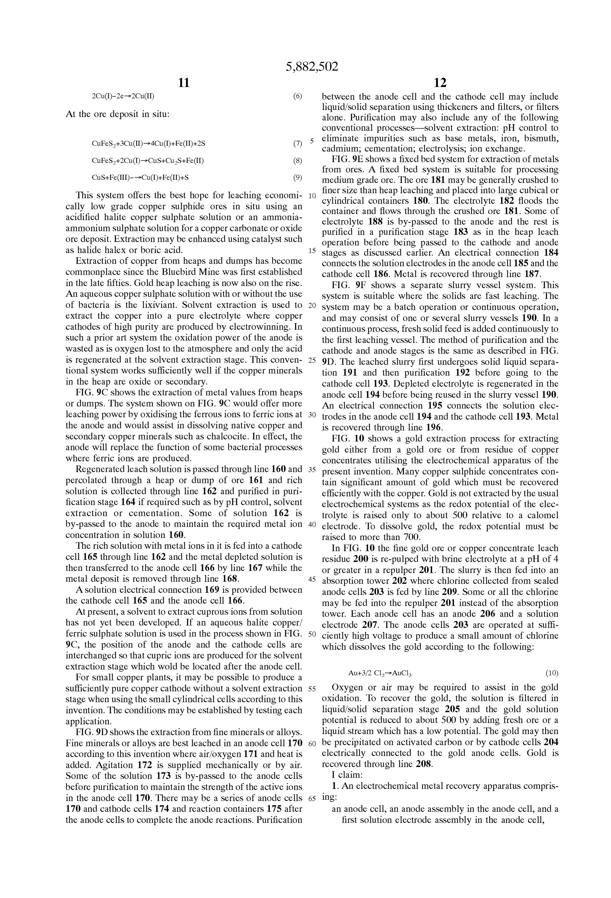
At the ore deposit in Situ: alone. Purification may also include any of the following conventional processes-Solvent extraction: pH control to eliminate impurities Such as base metals, iron, bismuth, cadmium, cementation; electrolysis, ion exchange.
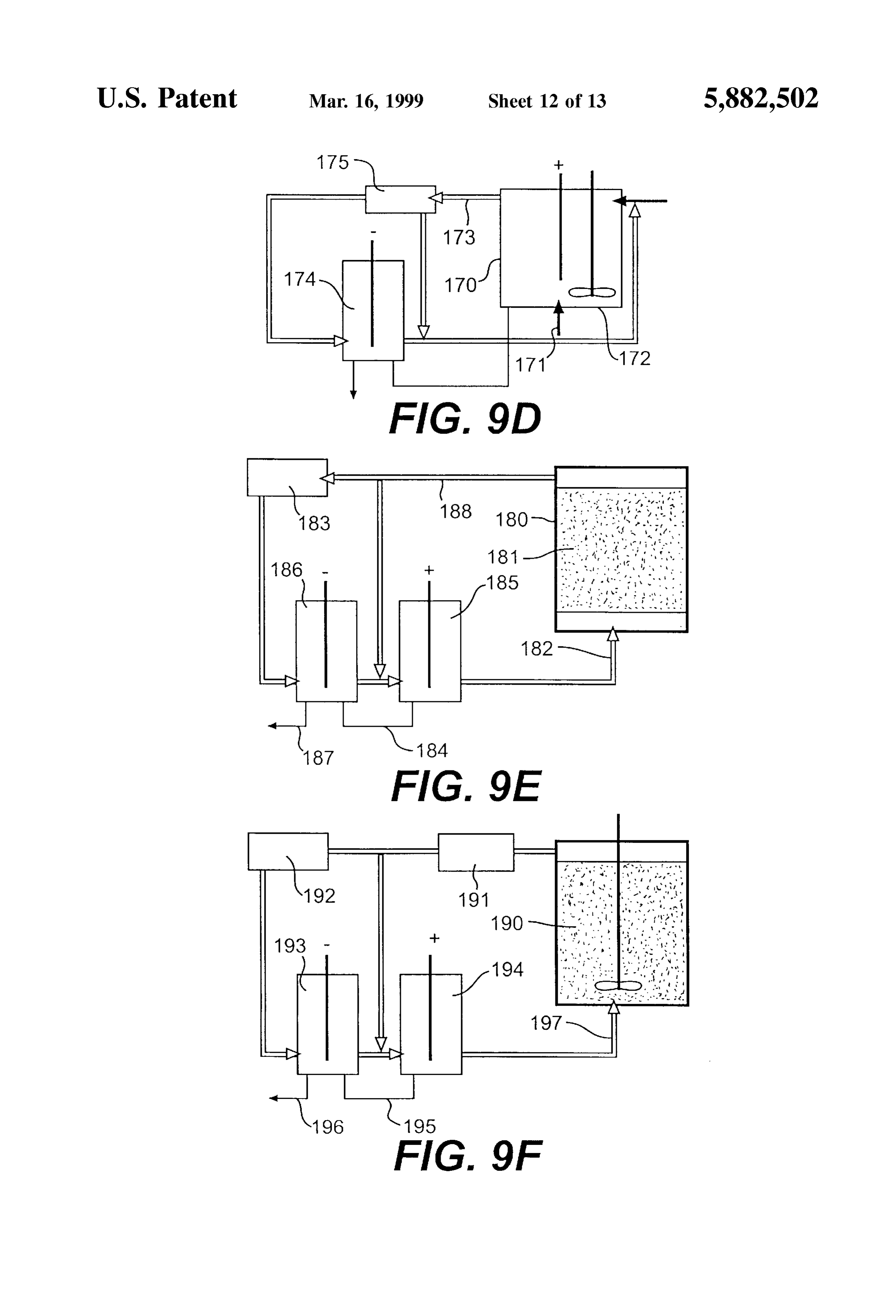
(8) FIG.9E shows a fixed bed system for extraction of metals from ores. A fixed bed System is Suitable for processing (9) medium grade ore. The ore 181 may be generally crushed to
This System offers the best hope for leaching economi finer Size than heap leaching and placed into large cubical or cally low grade copper Sulphide ores in Situ using an cylindrical containers 180. The electrolyte 182 floods the acidified halite copper Sulphate Solution or an ammonia electrolyte 188flows container and through the crushed ore 181. Some of is by-passed to the anode and the rest is ammonium Sulphate Solution for a copper carbonate or oxide purified in a purification Stage 183 as in the heap leach ore deposit. Extraction may be enhanced using catalyst Such operation before being passed to the cathode and anode as halide haleX or boric acid. 15
Stages as discussed earlier. An electrical connection 184
Extraction of copper from heaps and dumps has become connects the Solution electrodes in the anode cell 185 and the commonplace since the Bluebird Mine was first established cathode cell 186. Metal is recovered through line 187. in the late fifties. Gold heap leaching is now also on the rise. FIG. 9F shows a separate slurry vessel system. This An aqueous copper Sulphate Solution with or without the use System is Suitable where the Solids are fast leaching. The of bacteria is the lixiviant. Solvent extraction is used to System may be a batch operation or continuous operation, extract the copper into a pure electrolyte where copper and may consist of one or several slurry vessels 190. In a cathodes of high purity are produced by electrowinning. In continuous process, fresh Solid feed is added continuously to Such a prior art System the oxidation power of the anode is the first leaching vessel. The method of purification and the wasted as is oxygen lost to the atmosphere and only the acid cathode and anode Stages is the same as described in FIG. is regenerated at the Solvent extraction Stage. This conven 25 9D. The leached slurry first undergoes solid liquid separa tional System works Sufficiently well if the copper minerals tion 191 and then purification 192 before going to the in the heap are oxide or Secondary. cathode cell 193. Depleted electrolyte is regenerated in the FIG. 9C shows the extraction of metal values from heaps anode cell 194 before being reused in the slurry vessel 190. or dumps. The system shown on FIG. 9C would offer more An electrical connection 195 connects the Solution elec leaching power by oxidising the ferrous ions to ferric ions at trodes in the anode cell 194 and the cathode cell 193. Metal the anode and would assist in dissolving native copper and is recovered through line 196.
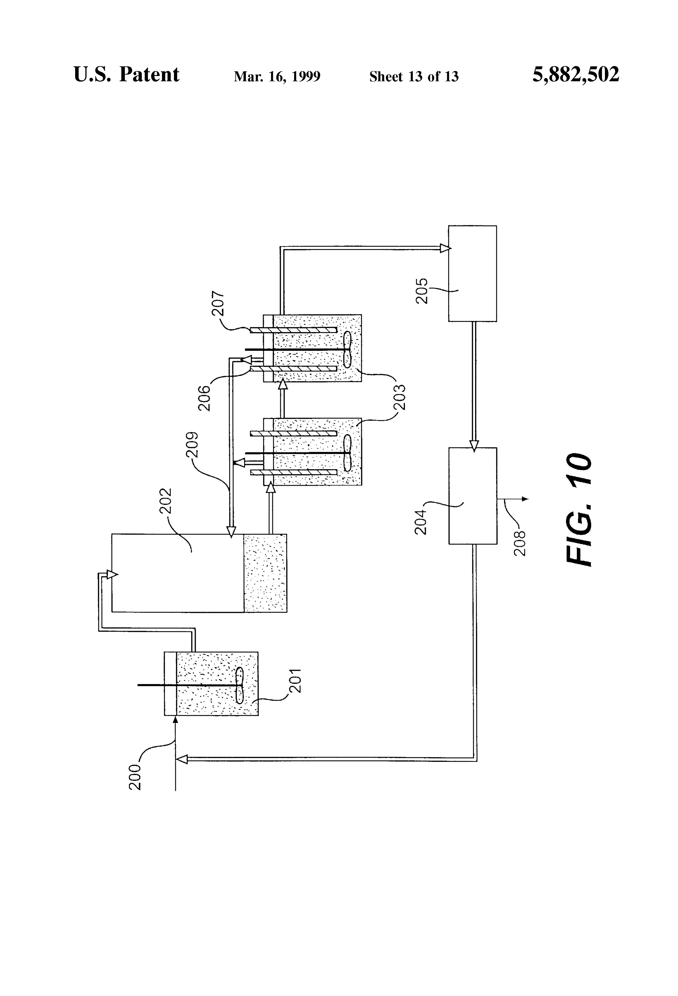
Secondary copper minerals Such as chalcocite. In effect, the FIG. 10 shows a gold extraction process for extracting anode will replace the function of Some bacterial processes gold either from a gold ore or from residue of copper where ferric ions are produced. concentrates utilising the electrochemical apparatus of the Regenerated leach Solution is passed through line 160 and 35 present invention. Many copper Sulphide concentrates con percolated through a heap or dump of ore 161 and rich tain significant amount of gold which must be recovered Solution is collected through line 162 and purified in puri efficiently with the copper. Gold is not extracted by the usual fication Stage 164 if required Such as by pH control, Solvent electrochemical Systems as the redox potential of the elec extraction or cementation. Some of Solution 162 is trolyte is raised only to about 500 relative to a calomel by-passed to the anode to maintain the required metal ion 40 electrode. To dissolve gold, the redox potential must be concentration in Solution 160. raised to more than 700.
The rich Solution with metal ions in it is fed into a cathode In FIG. 10 the fine gold ore or copper concentrate leach cell 165 through line 162 and the metal depleted solution is residue 200 is re-pulped with brine electrolyte at a pH of 4 then transferred to the anode cell 166 by line 167 while the or greater in a repulper 201. The slurry is then fed into an metal deposit is removed through line 168. 45 absorption tower 202 where chlorine collected from sealed A solution electrical connection 169 is provided between anode cells 203 is fed by line 209. Some or all the chlorine the cathode cell 165 and the anode cell 166. may be fed into the repulper 201 instead of the absorption At present, a Solvent to extract cuprous ions from Solution tower. Each anode cell has an anode 206 and a Solution has not yet been developed. If an aqueous halite copper/ electrode 207. The anode cells 203 are operated at Suffi ferric Sulphate Solution is used in the process shown in FIG. 50 ciently high Voltage to produce a Small amount of chlorine 9C, the position of the anode and the cathode cells are which dissolves the gold according to the following: interchanged So that cupric ions are produced for the Solvent extraction Stage which wold be located after the anode cell. Au+3/2 Cl->AuCls (10) For Small copper plants, it may be possible to produce a
Sufficiently pure copper cathode without a Solvent extraction 55 Oxygen or air may be required to assist in the gold Stage when using the Small cylindrical cells according to this oxidation. To recover the gold, the Solution is filtered in invention. The conditions may be established by testing each liquid/solid Separation Stage 205 and the gold Solution application. potential is reduced to about 500 by adding fresh ore or a FIG. 9D shows the extraction from fine minerals or alloys. liquid Stream which has a low potential. The gold may then Fine minerals or alloys are best leached in an anode cell 170 60 be precipitated on activated carbon or by cathode cells 204 according to this invention where air/oxygen 171 and heat is electrically connected to the gold anode cells. Gold is added. Agitation 172 is Supplied mechanically or by air. recovered through line 208.
Some of the solution 173 is by-passed to the anode cells I claim:
before purification to maintain the Strength of the active ions 1. An electrochemical metal recovery apparatus compris in the anode cell 170. There may be a series of anode cells 65 Ing:
170 and cathode cells 174 and reaction containers 175 after an anode cell, an anode assembly in the anode cell, and a the anode cells to complete the anode reactions. Purification first Solution electrode assembly in the anode cell,
Page 21
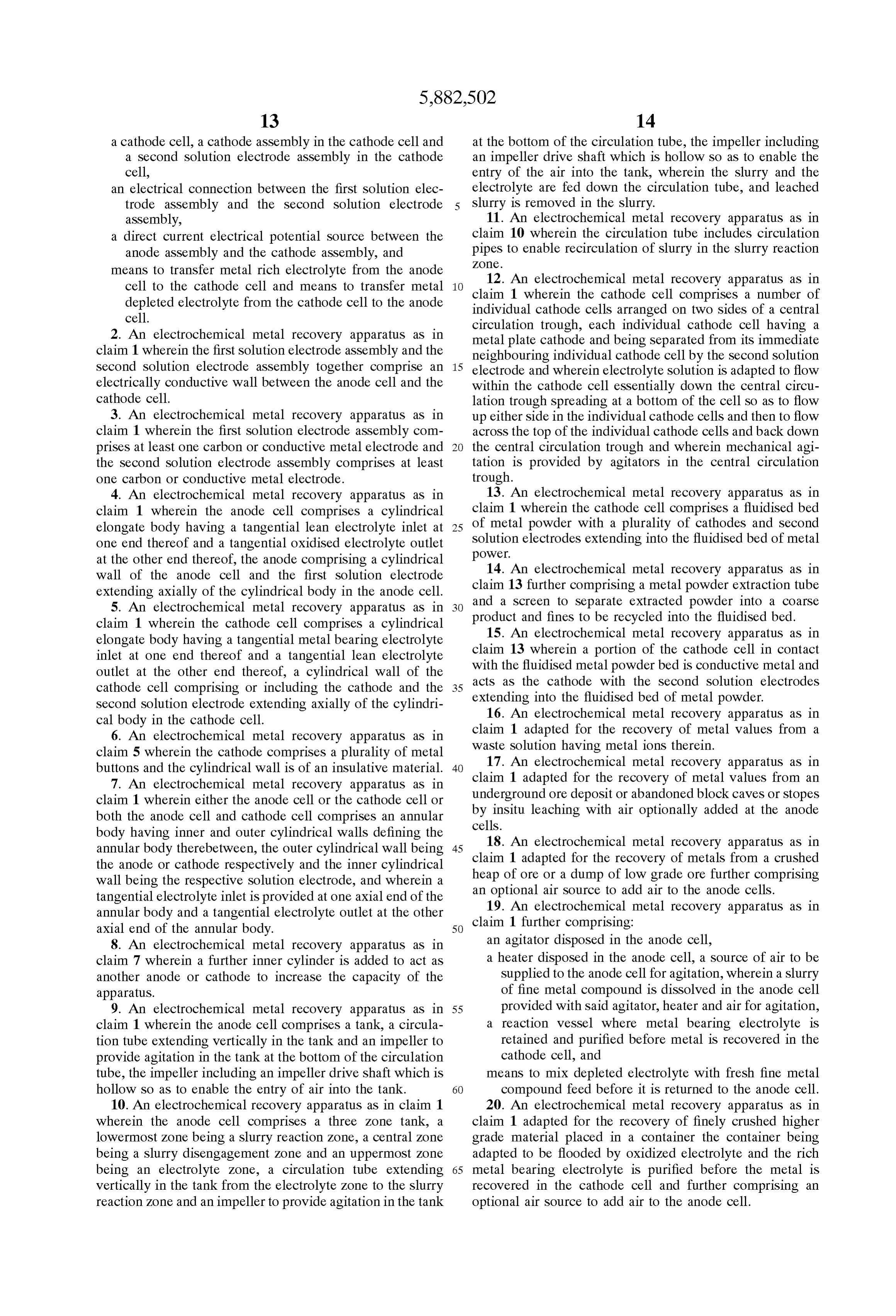
a cathode cell, a cathode assembly in the cathode cell and at the bottom of the circulation tube, the impeller including a Second Solution electrode assembly in the cathode an impeller drive shaft which is hollow so as to enable the cell, entry of the air into the tank, wherein the slurry and the an electrical connection between the first Solution elec electrolyte are fed down the circulation tube, and leached trode assembly and the Second Solution electrode Slurry is removed in the Slurry.
assembly, 11. An electrochemical metal recovery apparatus as in a direct current electrical potential Source between the claim 10 wherein the circulation tube includes circulation anode assembly and the cathode assembly, and pipes to enable recirculation of slurry in the Slurry reaction ZOC.
means to transfer metal rich electrolyte from the anode 12. An electrochemical metal recovery apparatus as in cell to the cathode cell and means to transfer metal depleted electrolyte from the cathode cell to the anode claim 1 wherein the cathode cell comprises a number of cell. individual cathode cells arranged on two sides of a central 2. An electrochemical metal recovery apparatus as in circulation trough, each individual cathode cell having a metal plate cathode and being Separated from its immediate claim 1 wherein the first solution electrode assembly and the neighbouring individual cathode cell by the Second Solution Second Solution electrode assembly together comprise an 15 electrode and wherein electrolyte Solution is adapted to flow electrically conductive wall between the anode cell and the within the cathode cell essentially down the central circu cathode cell. lation trough spreading at a bottom of the cell So as to flow 3. An electrochemical metal recovery apparatus as in up either side in the individual cathode cells and then to flow claim 1 wherein the first solution electrode assembly com acroSS the top of the individual cathode cells and back down prises at least one carbon or conductive metal electrode and the central circulation trough and wherein mechanical agi the Second Solution electrode assembly comprises at least tation is provided by agitators in the central circulation one carbon or conductive metal electrode. trough.
4. An electrochemical metal recovery apparatus as in 13. An electrochemical metal recovery apparatus as in claim 1 wherein the anode cell comprises a cylindrical claim 1 wherein the cathode cell comprises a fluidised bed elongate body having a tangential lean electrolyte inlet at 25 of metal powder with a plurality of cathodes and Second one end thereof and a tangential oxidised electrolyte outlet power.solution electrodes extending into the fluidised bed of metal at the other end thereof, the anode comprising a cylindrical 14. An electrochemical metal recovery apparatus as in wall of the anode cell and the first Solution electrode extending axially of the cylindrical body in the anode cell. claim 13 further comprising a metal powder extraction tube 5. An electrochemical metal recovery apparatus as in and a Screen to Separate extracted powder into a coarse claim 1 wherein the cathode cell comprises a cylindrical product and fines to be recycled into the fluidised bed. 15. An electrochemical metal recovery apparatus as in elongate body having a tangential metal bearing electrolyte inlet at one end thereof and a tangential lean electrolyte claim 13 wherein a portion of the cathode cell in contact outlet at the other end thereof, a cylindrical wall of the with the fluidised metal powder bed is conductive metal and acts as the cathode with the Second Solution electrodes cathode cell comprising or including the cathode and the 35 extending into the fluidised bed of metal powder. Second Solution electrode extending axially of the cylindri cal body in the cathode cell. 16. An electrochemical metal recovery apparatus as in 6. An electrochemical metal recovery apparatus as in claim 1 adapted for the recovery of metal values from a claim 5 wherein the cathode comprises a plurality of metal waste Solution having metal ions therein. 17. An electrochemical metal recovery apparatus as in buttons and the cylindrical wall is of an insulative material. 40 claim 1 adapted for the recovery of metal values from an 7. An electrochemical metal recovery apparatus as in underground ore deposit or abandoned block caves or Stopes claim 1 wherein either the anode cell or the cathode cell or both the anode cell and cathode cell comprises an annular by insitu leaching with air optionally added at the anode body having inner and outer cylindrical walls defining the cells.
annular body therebetween, the outer cylindrical wall being 45 claim 18. An electrochemical metal recovery apparatus as in the anode or cathode respectively and the inner cylindrical 1 adapted for the recovery of metals from a crushed wall being the respective Solution electrode, and wherein a heap of ore or a dump of low grade ore further comprising tangential electrolyte inlet is provided at one axial end of the an optional air Source to add air to the anode cells. annular body and a tangential electrolyte outlet at the other claim 19. An electrochemical metal recovery apparatus as in axial end of the annular body. 50 1 further comprising:
8. An electrochemical metal recovery apparatus as in an agitator disposed in the anode cell, claim 7 wherein a further inner cylinder is added to act as a heater disposed in the anode cell, a Source of air to be another anode or cathode to increase the capacity of the Supplied to the anode cell for agitation, wherein a slurry apparatuS. of fine metal compound is dissolved in the anode cell 9. An electrochemical metal recovery apparatus as in 55 provided with Said agitator, heater and air for agitation, claim 1 wherein the anode cell comprises a tank, a circula a reaction vessel where metal bearing electrolyte is tion tube extending vertically in the tank and an impeller to retained and purified before metal is recovered in the provide agitation in the tank at the bottom of the circulation cathode cell, and tube, the impeller including an impeller drive shaft which is means to mix depleted electrolyte with fresh fine metal hollow so as to enable the entry of air into the tank. 60 compound feed before it is returned to the anode cell. 10. An electrochemical recovery apparatus as in claim 1 20. An electrochemical metal recovery apparatus as in wherein the anode cell comprises a three Zone tank, a claim 1 adapted for the recovery of finely crushed higher lowermost Zone being a slurry reaction Zone, a central Zone grade material placed in a container the container being being a slurry disengagement Zone and an uppermost Zone adapted to be flooded by oxidized electrolyte and the rich being an electrolyte Zone, a circulation tube extending 65 metal bearing electrolyte is purified before the metal is vertically in the tank from the electrolyte Zone to the slurry recovered in the cathode cell and further comprising an reaction Zone and an impeller to provide agitation in the tank optional air Source to add air to the anode cell.
Page 22
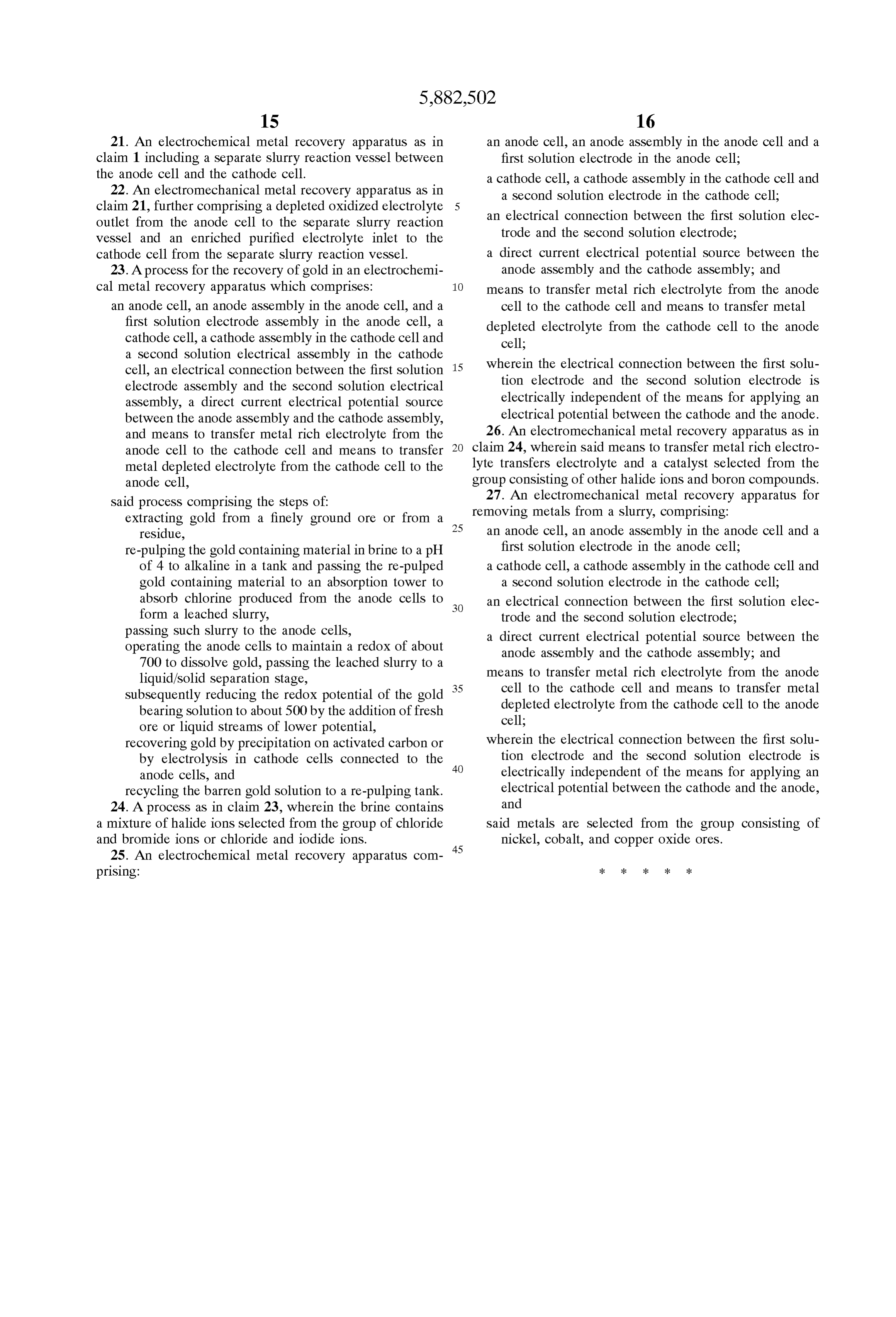
21. An electrochemical metal recovery apparatus as in an anode cell, an anode assembly in the anode cell and a claim 1 including a separate Slurry reaction vessel between first Solution electrode in the anode cell; the anode cell and the cathode cell. a cathode cell, a cathode assembly in the cathode cell and 22. An electromechanical metal recovery apparatus as in a Second Solution electrode in the cathode cell; claim 21, further comprising a depleted oxidized electrolyte an electrical connection between the first Solution elec outlet from the anode cell to the Separate slurry reaction vessel and an enriched purified electrolyte inlet to the trode and the Second Solution electrode, cathode cell from the Separate slurry reaction vessel. a direct current electrical potential Source between the 23. A proceSS for the recovery of gold in an electrochemi anode assembly and the cathode assembly; and cal metal recovery apparatus which comprises: 1O means to transfer metal rich electrolyte from the anode an anode cell, an anode assembly in the anode cell, and a cell to the cathode cell and means to transfer metal first Solution electrode assembly in the anode cell, a depleted electrolyte from the cathode cell to the anode cathode cell, a cathode assembly in the cathode cell and cell;
a Second Solution electrical assembly in the cathode wherein the electrical connection between the first Solu cell, an electrical connection between the first Solution 15 tion electrode and the Second Solution electrode is electrode assembly and the Second Solution electrical electrically independent of the means for applying an assembly, a direct current electrical potential Source between the anode assembly and the cathode assembly, electrical potential between the cathode and the anode. and means to transfer metal rich electrolyte from the 26. An electromechanical metal recovery apparatus as in anode cell to the cathode cell and means to transfer claim 24, wherein Said means to transfer metal rich electro metal depleted electrolyte from the cathode cell to the lyte transferS electrolyte and a catalyst Selected from the anode cell, group consisting of other halide ions and boron compounds. Said proceSS comprising the Steps of: 27. An electromechanical metal recovery apparatus for extracting gold from a finely ground ore or from a 25 removing metals from a slurry, comprising: residue, an anode cell, an anode assembly in the anode cell and a re-pulping the gold containing material in brine to a pH first Solution electrode in the anode cell; of 4 to alkaline in a tank and passing the re-pulped a cathode cell, a cathode assembly in the cathode cell and gold containing material to an absorption tower to a Second Solution electrode in the cathode cell; absorb chlorine produced from the anode cells to an electrical connection between the first Solution elec form a leached slurry, trode and the Second Solution electrode, passing Such slurry to the anode cells, a direct current electrical potential Source between the operating the anode cells to maintain a redox of about anode assembly and the cathode assembly; and 700 to dissolve gold, passing the leached slurry to a liquid/solid Separation Stage, means to transfer metal rich electrolyte from the anode Subsequently reducing the redox potential of the gold 35 cell to the cathode cell and means to transfer metal bearing solution to about 500 by the addition of fresh depleted electrolyte from the cathode cell to the anode ore or liquid Streams of lower potential, cell;
recovering gold by precipitation on activated carbon or wherein the electrical connection between the first Solu by electrolysis in cathode cells connected to the 40 tion electrode and the Second Solution electrode is anode cells, and electrically independent of the means for applying an recycling the barren gold Solution to a re-pulping tank. electrical potential between the cathode and the anode, 24. A proceSS as in claim 23, wherein the brine contains and a mixture of halide ions Selected from the group of chloride Said metals are Selected from the group consisting of and bromide ions or chloride and iodide ions. nickel, cobalt, and copper oxide ores. 25. An electrochemical metal recovery apparatus com 45 prising: k k k k k
Provenance
- Collection
- Cited prior art
- Original PDF
- patentimages.storage.googleapis.com →
- Filed
- 1996-09-25
- Pages
- 22
- Method
- pdftotext (the PDF's own text layer) + pdftoppm 300dpi page scans
- Source
- Google Patents bibliographic record
- Granted
- 1999-03-16
- Inventors
- Rodolfo Gomez; RMG Services Pty Ltd
- Transcribed from
- patentimages.storage.googleapis.com →