patent · US5862799
Control of a heliostat field in a solar energy plant
26 January 1999
Page 1 — bibliographic record
United States Patent (19) 11 Patent Number: 5,862,799 Yogev et al. (45) Date of Patent: Jan. 26, 1999 54 CONTROL OF A HELIOSTAT FIELD INA 4,424,801 1/1984 Mori ........................................ 126/578 SOLAR ENERGY PLANT 4,445,030 4/1984 Carlton ... 250/203.4 4,484,565 11/1984 Mori ........................................ 126/578 75 Inventors: Amnon Yogev, Rehovot; Vladimir 4,519,382 5/1985 Gerwin .................................... 126/578 Krupkin, Rishon, both of Israel 73 Assignee: Yeda Research And Development Primary Examiner James C. Yeung Company Ltd., Rehovot, Israel Attorney, Agent, or Firm-Gary M. Nath; Harold L. Novick; Nath & Associates
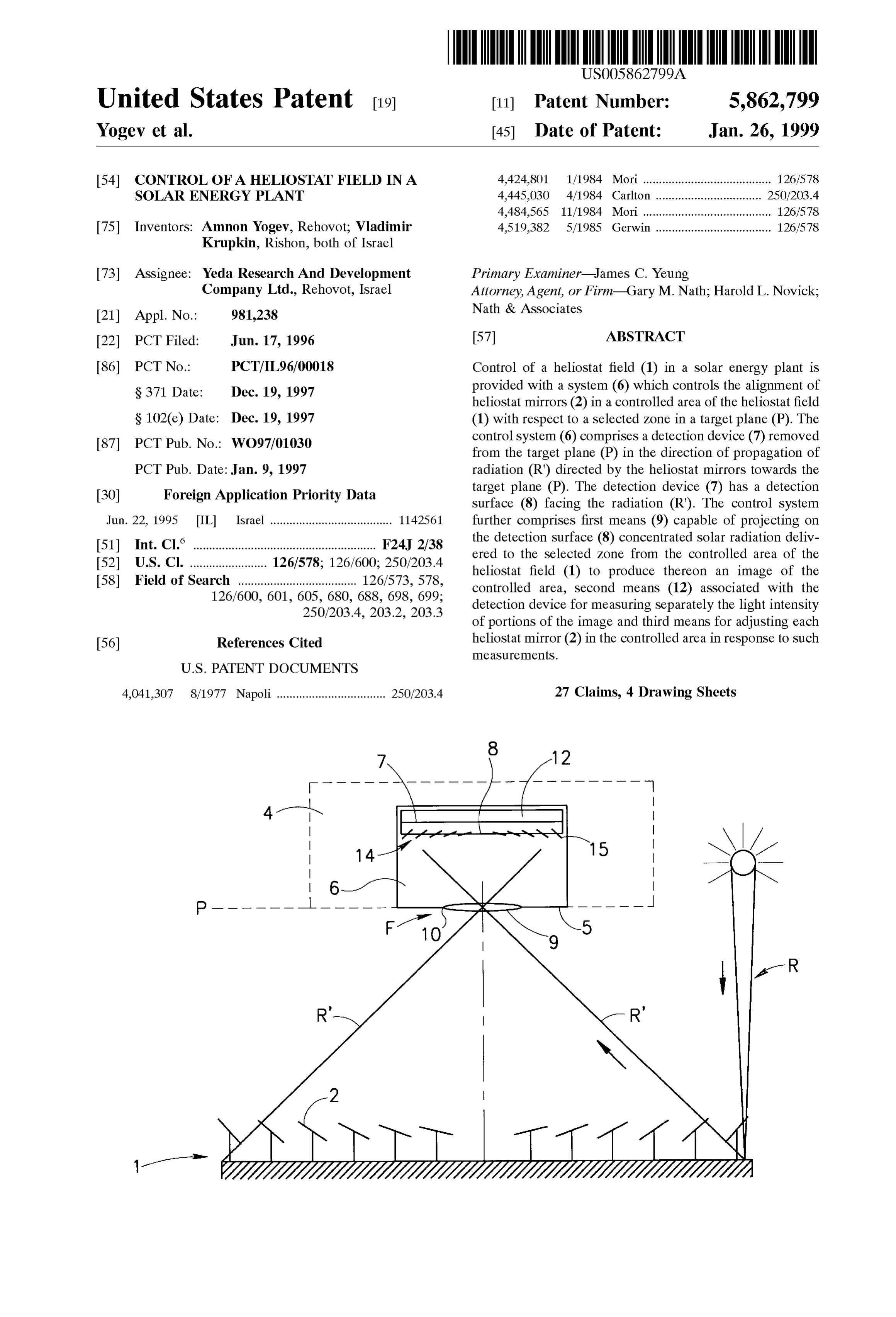
22 PCT Filed: Jun. 17, 1996 57 ABSTRACT 86 PCT No.: PCT/IL96/00018 Control of a heliostat field (1) in a Solar energy plant is S371 Date: Dec. 19, 1997 provided with a system (6) which controls the alignment of heliostat mirrors (2) in a controlled area of the heliostat field
S 102(e) Date: Dec. 19, 1997 (1) with respect to a selected Zone in a target plane (P). The 87 PCT Pub. No.: WO97/01030 control System (6) comprises a detection device (7) removed from the target plane (P) in the direction of propagation of
PCT Pub. Date:Jan. 9, 1997 radiation (R) directed by the heliostat mirrors towards the 30 Foreign Application Priority Data target plane (P). The detection device (7) has a detection surface (8) facing the radiation (R'). The control system
Jun. 22, 1995 IIL Israel ...................................... 1142561 further comprises first means (9) capable of projecting on (51) Int. Cl." ......................................................... F24J 2/38 the detection Surface (8) concentrated Solar radiation deliv ered to the selected Zone from the controlled area of the 52 U.S. Cl. ........................ 126/578; 126/600; 250/203.4 heliostat field (1) to produce thereon an image of the 58 Field of Search ..................................... 126/573,578, controlled area, Second means (12) associated with the 126/600, 601, 605, 680, 688, 698, 699; detection device for measuring Separately the light intensity 250/203.4, 203.2, 203.3 of portions of the image and third means for adjusting each 56) References Cited heliostat mirror (2) in the controlled area in response to Such measurementS.
4,041.307 8/1977 Napoli.................................. 250/203.4 27 Claims, 4 Drawing Sheets
Page 2
Drawing sheet — no readable text.
Page 3
Drawing sheet — no readable text.
Page 4
Drawing sheet — no readable text.
Page 5
Drawing sheet — no readable text.
Page 6
CONTROL OF A HELIOSTAT FIELD INA It has been Suggested to control the orientation of each SOLAR ENERGY PLANT heliostat mirror on the basis of detection of the direction of light reflected by the mirror, by means of a detector attached
FIELD OF THE INVENTION thereto. However, Such a control System requires a high The invention relates to the control of a heliostat field for number of detectors each of which has to be properly aligned with respect to both the target plane and mirror.
use in a Solar energy plant that Serves for conversion of a Furthermore, Such a System cannot provide for correction of concentrated Solar radiation into utilizable energy. errors caused by misalignments of the facets, or dislocation BACKGROUND OF THE INVENTION of the target plane or of any of the detectors. 1O Conventionally, the initial alignment of the heliostat field
In the following description and claims, the term “target and of individual heliostat mirrors thereof is based on plane' of a heliostat field means a plane in which the measurements of the intensity of the light Spots in the target heliostat field forms an image of the Sun, which is either the plane. However, this procedure is inefficient because the focal plane of the heliostat field or a plane conjugate overlapping light Spots Simultaneously produced by the there with Such as, for example, the focal plane of an optical 15 heliostat mirrors and which together constitute a Zone of System including the heliostat field and one or more addi concentrated Solar radiation, cannot be identified individu tional reflectors which redirect the Solar radiation concen ally and consequently the heliostat mirrors have to be trated by the heliostat field in direction of a solar receiver. In aligned manually one after the other by qualified perSonnel. Obviously this procedure is very slow and has the further most cases, the target plane coincides with the radiation inlet drawback that during the alignment procedure each of the of a solar receiver chamber. The term “alignment” used in manually handled heliostat mirrors is excluded from radia relation to the heliostat field Signifies the orientation of tion delivery for the heliostat mirrors and/or individual facets thereof, if any, So whereby the amount ofduration of the alignment procedure, as to focus reflected and concentrated light into the target where the heliostat mirrors are light collected is reduced. Moreover, composed of facets, the plane and, in particular, onto the radiation inlet of the Solar intensity of the individual Small light spots produced by each receiver chamber. 25 facet of a heliostat mirror that has to be aligned is only a A conventional Solar energy plant of the kind Specified, fraction of the total intensity of the full spot produced by that Such as disclosed, for example, by F. Ramos et al. in mirror and can be discerned on the background thereof only “Optimization of a Central Receiver Solar Electric Power with great difficulty, which complicates the adjustment of Plant by the ASpoc Program, Proc. 4-th. intern symp. on the individual facets of each mirror and gives rise to inac research, development and applications of Solar thermal curacies.
technology, New-York, pp. 61-70, 1990, comprises a solar BRIEF DESCRIPTION OF THE INVENTION energy receiver placed within a chamber and a heliostat field in the form of a large Fresnel reflector having a target plane It is the object of the present invention to provide a Solar and consisting of a plurality of concentrating heliostat energy plant of the kind specified comprising an improved mirrors of a generally concave shape. Each heliostat mirror 35 heliostat field with means for control thereof. reflects the incoming Solar radiation towards the target plane It is another object of the present invention to provide an and there is thus formed thereby in the target plane a improved heliostat field and means for control thereof. plurality of light Spots, which together constitute a Zone of In accordance with one aspect of the present invention concentrated Solar radiation delivered by the heliostat field there is provided a Solar energy plant comprising a heliostat to the inlet of the receiver chamber. Each heliostat mirror is 40 field having a plurality of heliostat mirrors for the concen either a single body or is made of Segments or facets having tration of Solar radiation and direction of the concentrated a Specific mutual orientation which may be different for Solar radiation towards a target plane, characterized in that different heliostats of the field. During operation the angular the heliostat field is provided with at least one control system position of each heliostat mirror at a given time is controlled for the control of the alignment of heliostat mirrors in a by computer means whose program adjusts automatically to 45 controlled area of the heliostat field with respect to a selected the position of the Sun. Zone in the target plane, comprising: The efficiency of the Solar energy plant, i.e. the conver a detection device removed from the target plane in a Sion rate of Solar energy into utilizable heat or electric direction of the radiation propagation and having a power, depends on the amount of Solar radiation collected by detection Surface facing the radiation; the heliostat field as well as on the Solar energy concentra 50 first means capable of projecting on Said detection Surface tion achieved at the inlet of the Solar energy receiver concentrated Solar radiation delivered to the Selected chamber. The amount and concentration of radiation deliv Zone from the controlled area of the heliostat field to ered to Said inlet depend to a large extent on the accuracy of produce thereon an image of Said controlled area, Said alignment of the heliostat field with the inlet of the Solar means having an optical entrance located essentially in receiver chamber. In other words, the higher the alignment 55 Said Selected Zone of the target plane, accuracy of the heliostat mirrors and of the adjustment of Second means associated with Said detection device for their facets, the better the overlap of the individual light measuring Separately the light intensity of portions of spots produced by different heliostat mirrors and by different Said image and adjusting each heliostat mirror in Said facets thereof in the target plane and, consequently, the controlled area in response to Such measurements, higher the amount and concentration of light delivered at the 60 third means for adjusting each heliostat mirror in Said inlet of the Solar receiver. controlled area in response to Such measurements. It is, therefore, clear that during operation of a Solar plant In accordance with another aspect of the present invention of the kind specified, the orientation of the heliostat mirrors there is provided, for use in a Solar energy plant, a heliostat and the disposition of their facets have to be continuously field of the specified kind.
controlled and adjusted in response to changing conditions, 65 In accordance with Still another aspect of the present in order to maximize the amount and light delivered to the invention, there is provided, for use in a heliostat field, a receiver chamber inlet. control System of the Specified kind.
Page 7
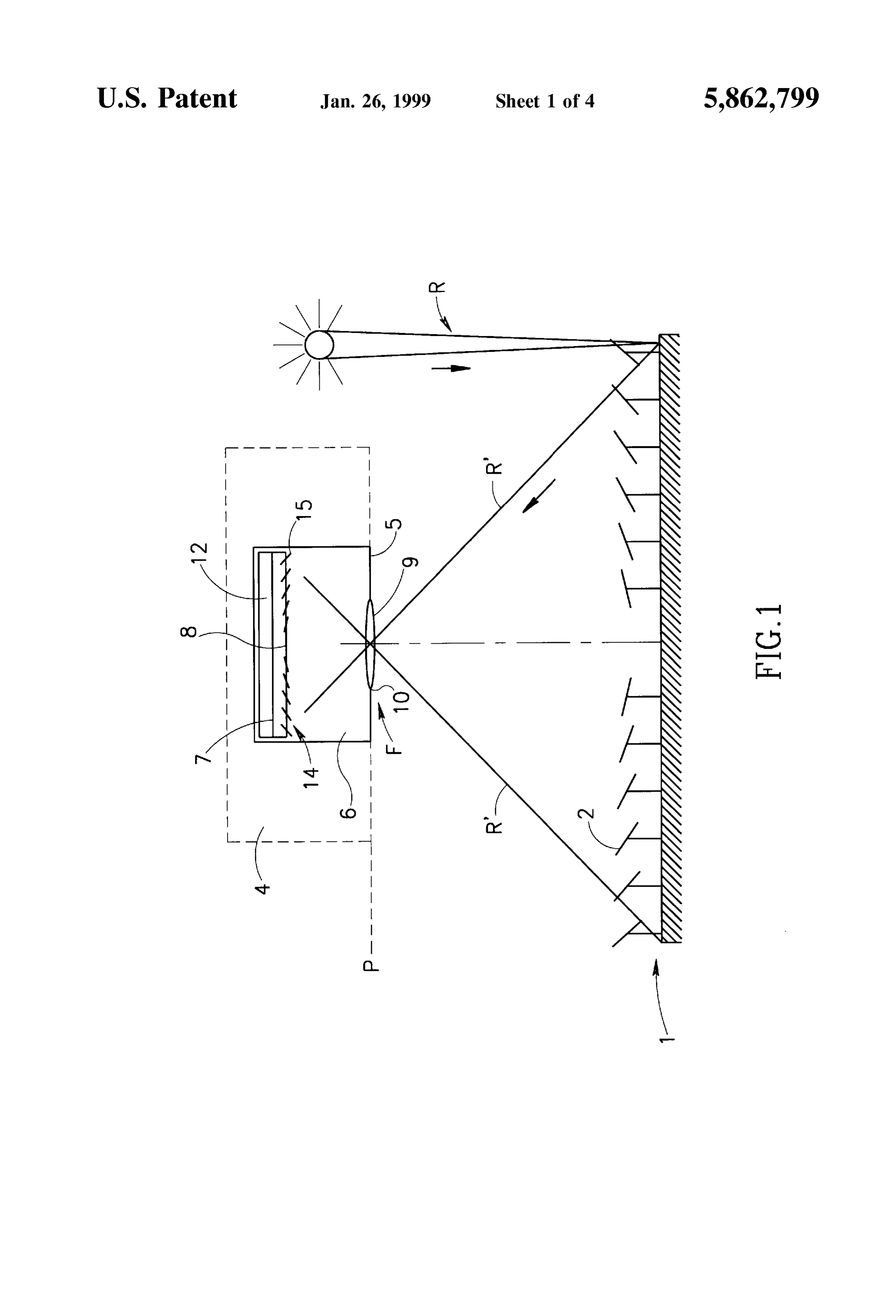
The controlled area of the heliostat field may be one single FIG. 1 is a schematic illustration of one embodiment of a mirror with either an integral reflecting Surface or a reflect Solar energy plant and a control System used therein accord ing Surface made of facets. Alternatively, the controlled area ing to the present invention;
may comprise a plurality of heliostat mirrors or even be the FIG. 2 is a schematic illustration of a disposition of the entire heliostat field.
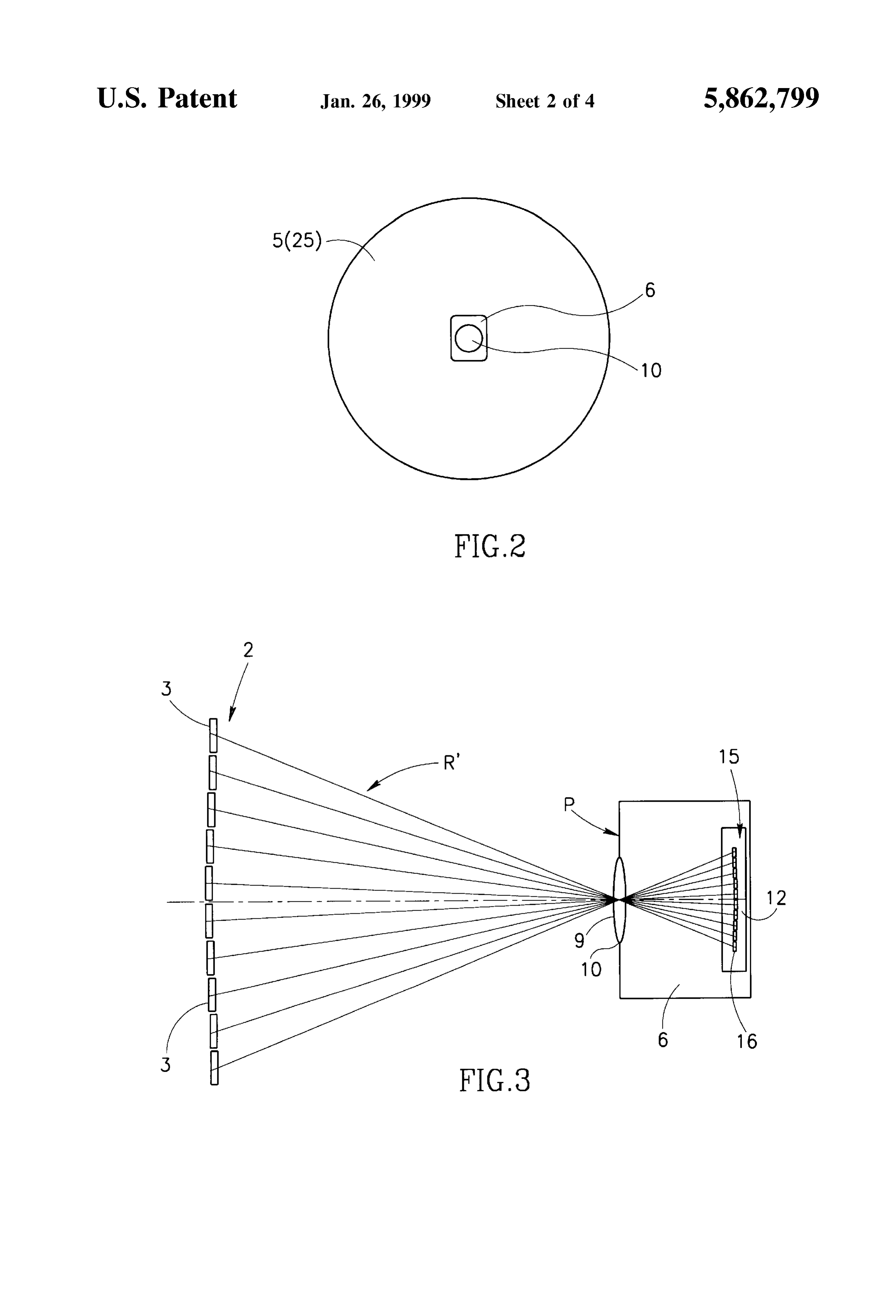
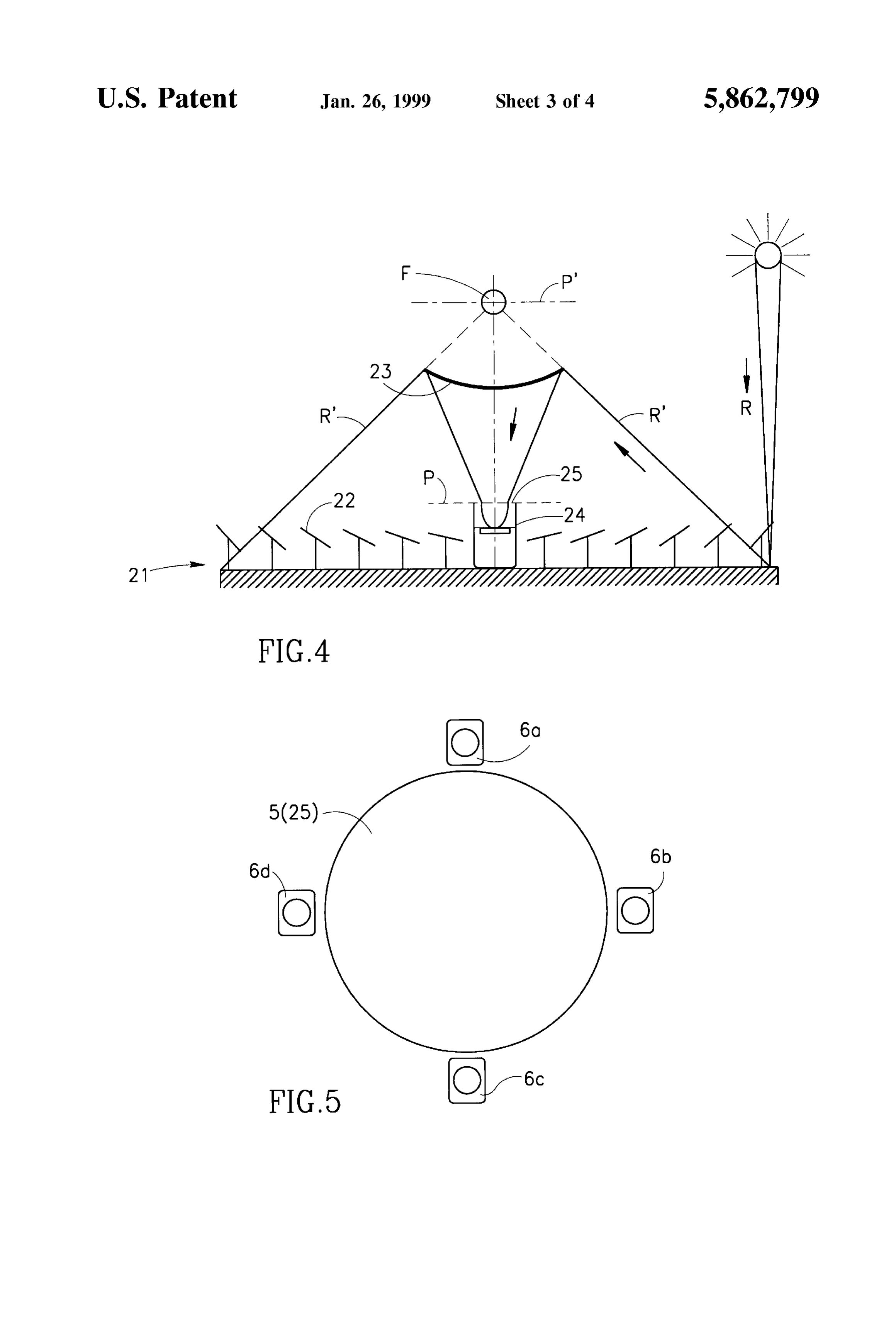
The Selected area of the target plane may be a central or control system of the present invention shown in FIG. 1, a peripheral region of the Zone of concentrated Solar radia with respect to the inlet of a Solar receiver; tion formed by the heliostat field in the target plane, or it FIG. 3 is a schematic illustration of one heliostat mirror may be the entire area of this Zone or it may rather be an area and of the control system of the plant shown in FIG. 1 drawn of the target plane located outside the Zone of concentrated to a larger Scale;
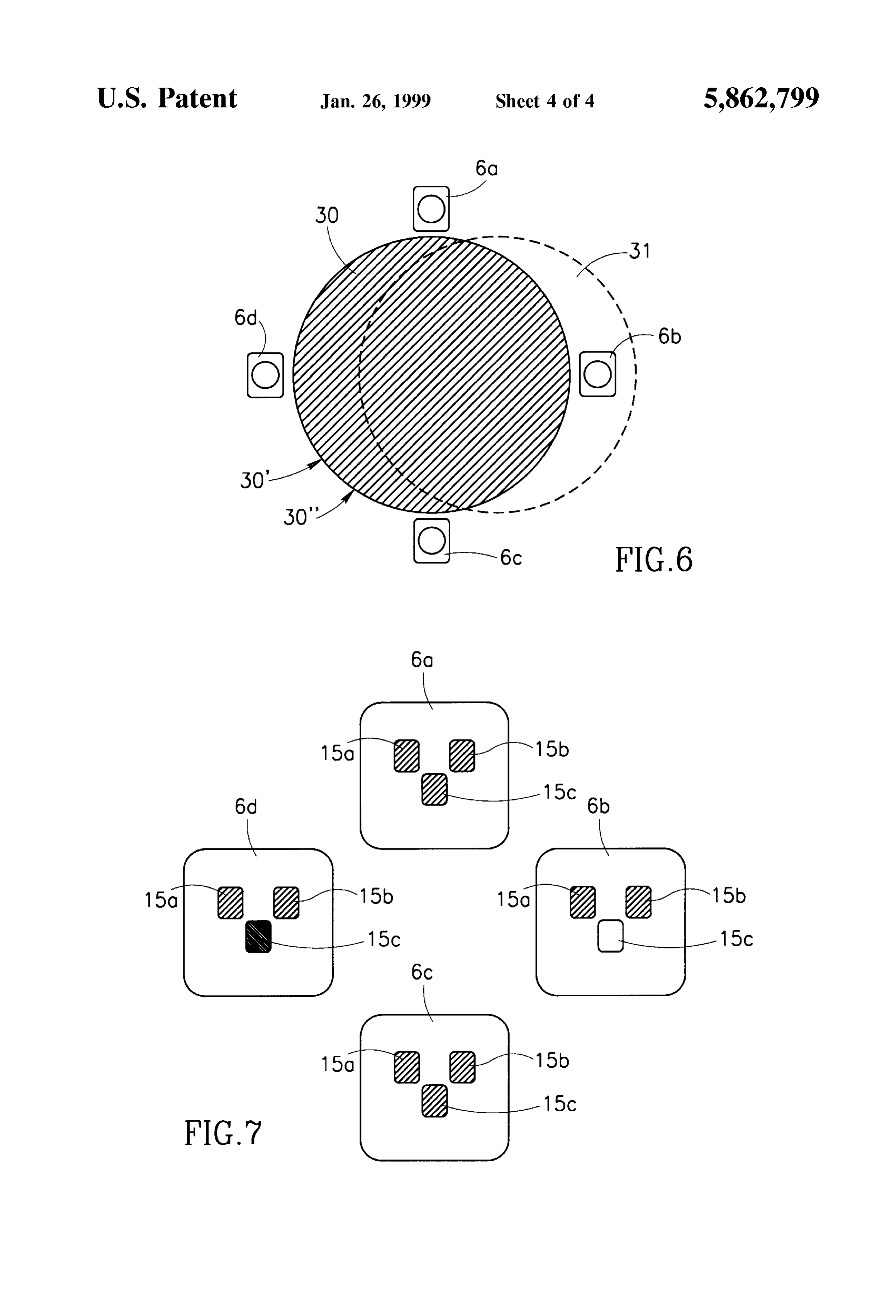
Solar radiation. FIG. 4 is a schematic illustration of another embodiment Preferably, Said first means are imaging means of any of a plant according to the present invention; Suitable kind Such as, for example, an aperture, lens, mirror, e.g. concave mirror, prism, etc. FIG. 5 is a schematic illustration of a disposition of a Preferably, Said Second means are capable of Simulta plurality of control Systems of the present invention, with neously measuring of the light intensity of portions of the 15 respect to the inlet of a Solar receiver; controlled area image and comprises an array of Suitable FIG. 6 illustrates a light Spot produced in the target plane detectorS Such as photodiodes, a CCD camera, a Scanning by three heliostat mirrors of which on is misaligned; and photodiode device or the like. Where the individual mirrors FIG. 7 illustrates the light intensity of images of the three are composed of facets, high-resolution measuring means heliostat are required in order to ensure that the light Spot produced the controlmirrors of which one is misaligned, measured by systems disposed as shown in FIG. 5.
by each of the facets is detected and measured.
Preferably, Said third means are computerized control DETAILED DESCRIPTION OF SPECIFIC means providing the automatic control of the heliostat EMBODIMENTS mirrors.
The fact that in accordance with the invention the con FIGS. 1 and 4 show two alternative embodiments of a centrated radiation delivered to the target plane by the 25 Solar plant for conversion of Solar radiation into utilizable heliostat mirrors of the controlled area is analyzed in a plane energy, of the kind which comprises a heliostat field for removed from Said target plane in a direction of the con concentration of the incoming Solar radiation, a central Solar centrated radiation enables simultaneous radiation intensity receiver for absorption of the concentrated radiation and a measurements of imageS produced by a plurality of indi System for control of the heliostat field according to the vidual heliostat mirrors and by their facets, which in turn present invention.
enables a simultaneous differential control of each mirror and its facets. The Solar energy plant shown in FIG. 1 comprises a Preferably, the Solar energy plant comprises a Solar radia heliostats field 1 consisting of a plurality of heliostat mirrors tion receiver mounted within a receiver chamber having a 2 which may, for example, be in the form of parabolic radiation inlet located essentially in the target plane of the 35 mirrors and which are made of facets 3 (FIG.3), the heliostat heliostat field. mirrorS 2 reflecting the incoming Solar radiation R towards According to one embodiment of the invention, the a target plane Plocated close the focal point F of the heliostat heliostat field is provided with one Single control System of field. During operation of the heliostat field 1, an angular the kind Specified, which may be located in the central position of each heliostat mirror is controlled by computer region of the radiation inlet of the receiver chamber, off 40 and adjusted automatically to track the Sun. The plant further center thereof or completely outside the receiver chamber. comprises a Solar receiver (not shown) mounted within a According to another embodiment, the heliostat field is receiver chamber 4 installed on top of a Solar tower (not provided with a plurality of control Systems at least Some of shown) in the vicinity of the focal point F of the heliostat which are preferably located at the periphery of the Zone of field and having a radiation inlet 5 located essentially in the concentrated Solar radiation formed by the heliostat field in 45 target plane P, and a control System 6 for the control of the the radiation inlet of the receiver chamber.
Preferably, the Solar energy plant comprises an additional heliostat the mirrorS 2, the control System 6 being mounted in vicinity of the Solar receiver.
reflector mounted on a Solar tower close to the focal point of As seen in FIGS. 1 and 3, the control system 6 comprises the heliostat field, which additional reflector redirects at least a portion of the concentrated Solar radiation delivered a detection device 7 removed from the target plane P in the by the heliostat field towards a target plane located close to 50 direction of the concentrated Solar radiation R and having a the base plane in which the heliostat field is installed. In such detection Surface 8 facing the radiation and imaging means an embodiment the control System provided in accordance 9 capable of projecting on the detection Surface 8 the with the present invention also enables detection of any radiation R' focussed on the target plane P by the heliostat dislocation of the reflector caused, for example, by tower field 1. The imaging means 9 have an optical entrance 10 Sway. Where the additional reflector is of the beam-splitter 55 located in the target plane P. In the present embodiment, the type the target plane of the heliostat field is located Substan optical entrance 10 of the imaging means 9 is disposed in the tially in the focal plane of the reflector. central region of the radiation inlet 5 of the receiver chamber In order to increase the concentration of Solar radiation, 4, the diameter of the optical entrance 10 being preferably the Solar receiver may be provided with a Secondary substantially less, for example about 1%, of that of the concentrator, preferably of a non-imaging type, which 60 radiation inlet 5. The imaging means 9 are in the form of a directs the solar radiation concentrated by the heliostat field lens, but it may also be an aperture, a prism, a mirror or any from the inlet of the receiver chamber into the interior Suitable combination thereof.
thereof.
The control System 6 further comprises measuring means
DESCRIPTION OF THE DRAWINGS 12 (shown Schematically) associated with the detection For better understanding, the present invention will now 65 device 7 for measuring a distribution of the light intensity in be described, by way of example only, with reference to the the detection Surface 8 and comprising an array of Suitable accompanying drawings in which detectors, Such as photodiodes, and preferably has a Sub
Page 8
S 6
Stantially high resolution. The measuring means 12 may also fact that the intensity of radiation reflected by individual be a CCD-camera, a Scanning photodiode or the like. heliostat mirrors and facets thereof is measured Separately The control System 6 further comprises a computerized and independently, enables a simultaneous differential con means (not shown) for the automatic control of each trol of the heliostat mirrors and their facets. heliostat mirror 2 in response to the light intensity measure AS shown in FIG. 5, the Solar energy plant according to mentS. the present invention may comprise a plurality of control Attention is now directed to FIG. 4 which shows another systems 6a, 6b, 6c and 6d located at the periphery of the embodiment of the Solar energy plant according to the radiation inlet 5, 25 of the receiver chamber 4, 2. present invention, where the control System 6 described The mode of operation of the control systems 6a to 6d is above is used. AS Seen, the Solar plant consists of a heliostats illustrated by FIGS. 6 and 7. FIG. 6 shows a radiation spot field 21 comprising a plurality of heliostat mirrorS 22 30 produced in the radiation inlet 5, 25 by heliostat mirrors directing concentrated radiation towards the focal point F of A, B and C of the heliostat field of the Solar plant. As seen, the heliostat field 1, a solar receiver (not shown) mounted the mirrors A and B are aligned properly So that their spots within a receiver chamber 24 installed in the vicinity of the 15 30' and 30" overlap and the mirror C is misaligned so that heliostat field 1 and having a radiation inlet 25 and an only a portion of its spot 31 overlaps with the spots 30' and additional reflector 23 mounted on a solar tower (not shown) 30". FIG. 7 illustrates light intensity of images 15a, 15b and close to the focal point F and redirecting the concentrated 15c of the three heliostat mirrors A, B and C produced by the radiation towards a target plane P coinciding with the imaging device of each of the control Systems 6a, 6b, 6c and Surface of the radiation inlet 25 of the receiver chamber 24. 6d on the detection Surface of its detection device. The The additional reflector is preferably a convex mirror. It can control of the heliostat mirrors A, B and C is based on the be of a beam-splitter type, in which case the heliostat field comparison of the light intensity of the images 15a, 15b and may have an additional target plane P' in the vicinity of the 15c of the heliostat mirrors formed at the detection Surface of the control systems 6a to 6d. The information provided by focal point F of the heliostat field 21. In order to increase the concentration of Solar radiation, the Solar receiver 25 is 25 the control Systems is used to calculate the required coor provided with a Secondary concentrator 26, preferably of a dinates of the heliostat mirror C and to accordingly adjust its non-imaging type, installed in the radiation inlet 95, which position.
directs the solar radiation concentrated by the heliostat field Thus, the present invention enables an automatic control 21 into the receiver cavity 24. of the heliostat mirrors during their operation So that mis The control system 6 used in the Solar plant shown in FIG. aligned heliostats continue radiation collection being Simul 4 is not seen in this figure but it is located in the manner taneously adjusted. With the control of heliostat field accord illustrated by FIG. 2, i.e. so that its optical entrance 10 is ing to the present invention, displacements of the target disposed in the central region of the radiation inlet 25 of the plane P or of the additional reflector 23 (FIG. 4), caused for receiver chamber 24. example by a tower Sway, can also be corrected. It should be mentioned with respect the Solar energy plant 35 The control System according to the present invention shown in both FIG. 1 and FIG. 4 that the control system 6 may also be used to control the reflectivity of heliostat may be located also off-center of the radiation inlet 5, 25 or mirrors and facets. It has to be mentioned that the Solar completely outside the receiver chamber 4, 24. energy plant and the control System designed according to The mode of operation of the control system 6 of the solar the present invention may have features different from those energy plant shown in FIGS. 1 and 4 will now be described 40 described above and shown in the accompanying drawings. with reference to FIGS. 1 and 3. For the control of the Thus, for example, the control System may be installed alignment of the heliostat mirrors 2 of the heliostat field 1 outside the central Solar receiver, the concentrated radiation with respect to the radiation inlet 5 of the receiver chamber being reflected or delivered thereto by any Suitable means, 4, the imaging means 9 of the control System 6 project the e.g. by a beam splitter. The control System may comprise Solar radiation R' reflected from the heliostat mirrors and 45 means for manual adjusting each heliostat mirror on the delivered to the optical entrance 10 of the imaging means 9 basis of the light intensity measurements. on to the detection Surface 8 of the detection device 7, We claim:
obtaining thereby on the detection Surface 8 an image 14 of 1. A Solar energy plant comprising a heliostats field with the heliostat field consisting of images 15 of the heliostat a plurality of heliostat mirrors for the concentration of Solar mirrors 2. As seen in FIG. 3, the image 15 of the heliostat 50 radiation and direction of the concentrated Solar radiation mirror 2 comprising facets 3 consists of individual images towards a target plane, and at least one control System for the 16 of the facets. The measuring means 12 measure Sepa control of the alignment of heliostat mirrors in a controlled rately the light intensity of images 15 and 16, if any. The area of the heliostat field with respect to a Selected Zone in intensity of radiation in the detection Surface 8 is propor the target plane, Said control System comprising a detection tional to the amount of radiation delivered by the heliostat 55 device associated with Said target plane and having a detec field to the optical entrance 10 of the imaging means and tion Surface, and adjusting means for adjusting the heliostat consequently to the radiation inlet 5 of the solar receiver 4. mirrors in Said controlled area based on measurements made When the heliostat mirrors and their facets are properly on the detection Surface of the detection device; aligned, the intensity of their images in the detection plane characterised in that 8 has a predetermined maximal value. Intensity of the 60 Said detection device of the control System is removed images of misaligned heliostat mirrors or facets is low. from the target plane in the direction of the concen The information provided by the light intensity measure trated Solar radiation, Said detection Surface facing Said ments is used for correction of the heliostats tracking concentrated radiation, Said control System further Strategy controlled by computer means and for adjustment of comprising first means having an optical entrance the heliostat facets. The orientation of misaligned heliostat 65 located essentially in Said Selected Zone of the target mirrors and/or their facets is automatically changed to plane and capable of projecting on Said detection establish a better or an optimal position thereof. Thus, the Surface the concentrated Solar radiation delivered to the
Page 9
Selected Zone from the controlled area of the heliostat redirects at least a portion of the concentrated Solar radiation field to produce thereon an image of Said controlled delivered by the heliostat field towards a target plane located area, and Second means associated with Said detection close to the base plane in which the heliostat field is device for measuring Separately the light intensity of installed.
portions of Said image of the controlled area. 5 23. A Solar energy plant according to claim 22, wherein 2. A Solar energy plant according to claim 1, wherein the Said additional reflector is of a beam-splitter type. controlled area of the heliostat field is one Single mirror. 24. A Solar energy plant according to claim 23, wherein 3. A Solar energy plant according to claim 1, wherein the the heliostat field has an additional target plane located in the controlled area of the heliostat field comprises a plurality of focal plane thereof.
25. A Solar energy plant according to claim 13, wherein heliostat mirrors.
4. A Solar energy plant according to claim 1, wherein the the Solar receiver comprises a Secondary concentrator which Selected area of the target plane is a central region of the from directs the solar radiation concentrated by the heliostat field Zone of concentrated Solar radiation formed by the heliostat thereof.the inlet of the receiver chamber into the interior field in the target plane.
5. A Solar energy plant according to claim 1, wherein the 15 26. For use in a Solar energy plant, a heliostat field having a plurality of heliostat mirrors for the concentration of Solar
Selected area of the target plane is a peripheral region of the radiation
Zone of concentrated Solar radiation formed by the heliostat towards a and direction of the concentrated Solar radiation target plane and having at least one control System field in the target plane.
6. A Solar energy plant according to claim 1, wherein the for the control of the alignment of heliostat mirrors in a Selected area of the target plane is located outside the Zone controlled area of the heliostat field with respect to a selected Zone in the target plane, Said control System comprising a of concentrated Solar radiation.
7. A Solar energy plant according to claim 1, wherein Said detection device associated with Said target plane and having a detection Surface, and adjusting means for adjusting the first means comprise an aperture.
8. A Solar energy plant according to claim 1, wherein Said heliostat mirrors in Said controlled area based on measure first means comprise a lens. 25 ments made on the detection Surface of the detection device; 9. A Solar energy plant according to claim 1, wherein Said characterised in that first means comprise a concave mirror. Said detection device of the control System is removed 10. A Solar energy plant according to claim 1, wherein from the target plane in the direction of the concen Said first means comprise a prism. trated Solar radiation, Said detection Surface facing Said 11. A Solar energy plant according to claim 1, wherein Said concentrated radiation, Said control System further Second means are capable of Simultaneously measuring of comprising first means having an optical entrance the light intensity of portions of the controlled area image. located essentially in Said Selected Zone of the target 12. A Solar energy plant according to claim 1, wherein plane and capable of projecting on said detection Said third means are computerized control means providing Surface the concentrated Solar radiation delivered to the the automatic control of the heliostat mirrors. 35 Selected Zone from the controlled area of the heliostat 13. A Solar energy plant according to claim 1, comprising field to produce thereon an image of Said controlled a Solar radiation receiver mounted within a receiver chamber area, and Second means associated with Said detection having a radiation inlet located essentially in the target plane device for measuring Separately the light intensity of of the heliostat field. portions of Said image of the controlled area. 14. A Solar energy plant according to claims 13, wherein 40 27. For use with a heliostat field having a plurality of Said at least one control System is located in the central heliostat mirrors for the concentration of Solar radiation and region of the radiation inlet of the receiver chamber. direction of the concentrated Solar radiation towards a target 15. A Solar energy plant according to claim 13, wherein plane, a System for control of the alignment of heliostat Said at least one control System is located eccentrically with mirrors in a controlled area of the heliostat field with respect respect to the radiation inlet of the receiver chamber. 45 to a Selected Zone in the target plane, Said System comprising 16. A Solar energy plant according to claim 13, wherein a detection device associated with Said target plane and Said at least one control System is located outside the having a detection Surface, and adjusting means for adjust receiver chamber. ing the heliostat mirrors in Said controlled area based on 17. A Solar energy plant according to claim 1, comprising measurements made on the detection Surface of the detection one Single control System. 50 device;
18. A Solar energy plant according to claim 1, comprising characterised in that a plurality of control Systems. Said detection device of the control System is removed 19. A Solar energy plant according to claim 18, wherein at from the target plane in the direction of the concen least Some of Said control Systems are located at the periph trated Solar radiation, Said detection Surface facing Said ery of the Zone of concentrated Solar radiation formed by the 55 concentrated radiation, Said control System further heliostat field in the radiation inlet of the receiver chamber. comprising first means having an optical entrance 20. A Solar energy plant according to claim 18, wherein located essentially in Said Selected Zone of the target the control of the heliostat mirrorS is based on the compari plane and capable of projecting on Said detection Son of the light intensity of the images of the heliostat Surface the concentrated Solar radiation delivered to the mirrors formed at the detection Surface of Said control 60 Selected Zone from the controlled area of the heliostat Systems. field to produce thereon an image of Said controlled 21. A Solar energy plant according to claim 1, wherein area, and Second means associated with Said detection Said target plane is the focal plane of the heliostat field. device for measuring Separately the light intensity of 22. A Solar energy plant according to claim 1, comprising portions of Said image of the controlled area. an additional reflector mounted on a Solar tower close to the 65 focal point of the heliostat field, which additional reflector k k k k k
Provenance
- Collection
- Cited prior art
- Original PDF
- patentimages.storage.googleapis.com →
- Filed
- 1996-06-17
- Pages
- 9
- Method
- pdftotext (the PDF's own text layer) + pdftoppm 300dpi page scans
- Source
- Google Patents bibliographic record
- Granted
- 1999-01-26
- Inventors
- Amnon Yogev; Vladimir Krupkin; Yeda Research and Development Co Ltd
- Transcribed from
- patentimages.storage.googleapis.com →