patent · US3125085
Control of fuel introduction to engine cylinder
17 March 1964
Page 1
Drawing sheet — no readable text.
Page 2
March 17, 1964 W. M. KAUFFMANN 3,125,085 CONTROL OF FUEL INTRODUCTION TO ENGINE CyLINDER Filed June 28, 1962 2 Sheets-Sheet 2 swer inct
Ap Pere crank trave
WILLIAM M. KAUFEMANN
INVENTOR
BY Šal A. ?éell
Page 3
United States Patent Office 3,125,085 Patented Mar. 17, 1964
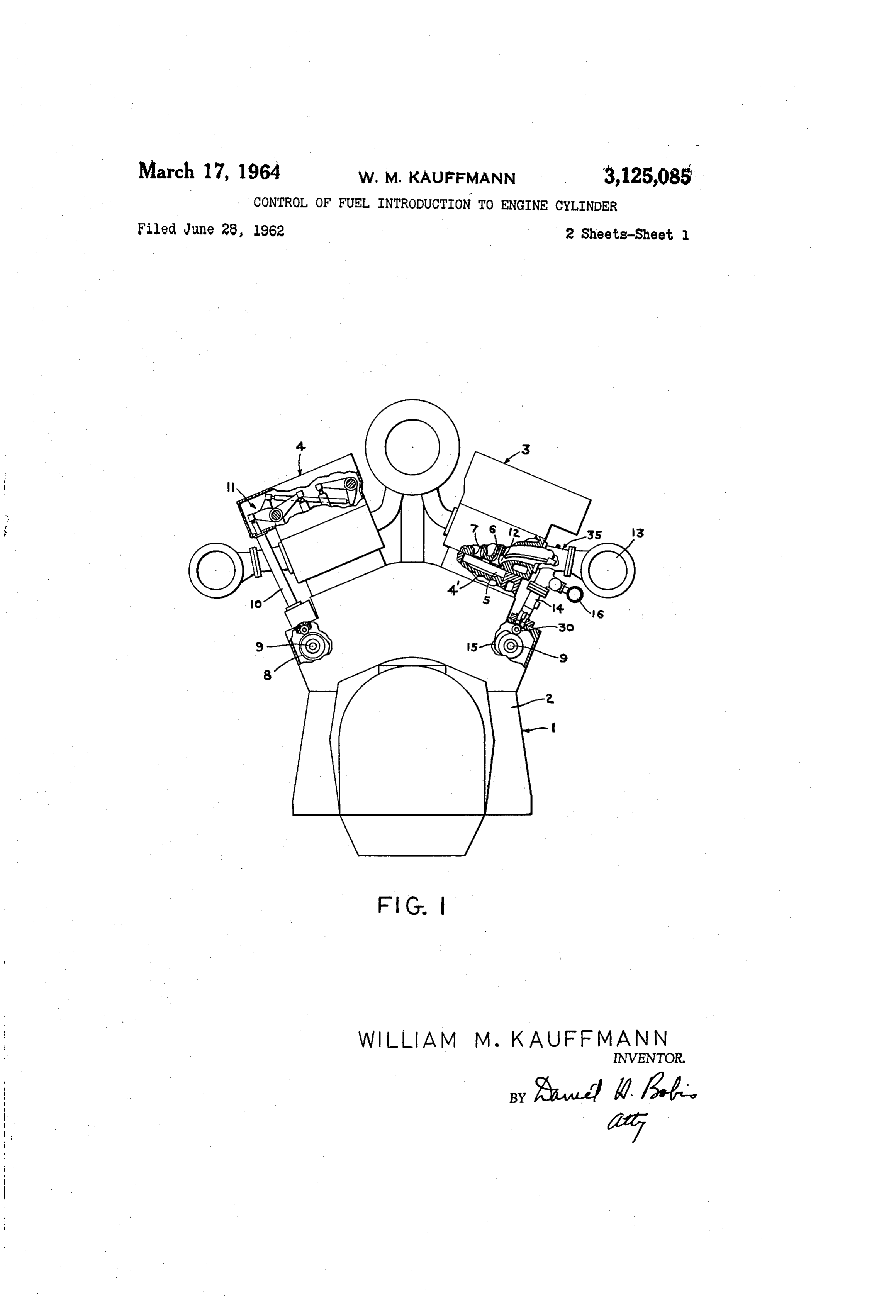
thereon will appear from the following description taken 3,125,085 in conjunction with the following drawings, in which:
CONTROL OF FUEL ENTRODUCTION TO
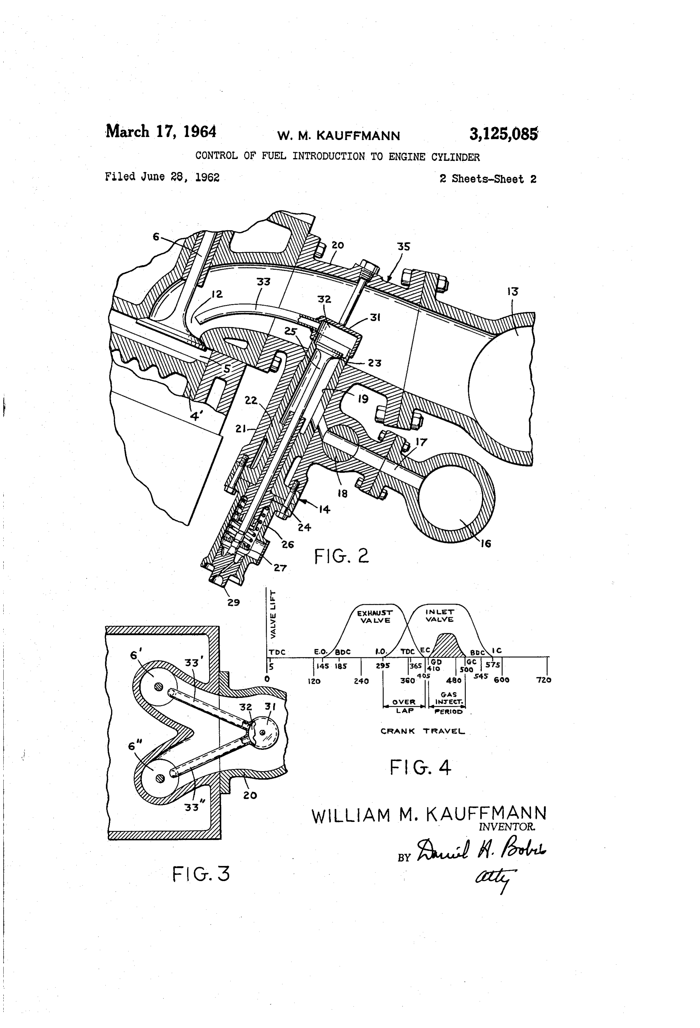
ENGINE CYLNDER FIGURE 1 is a side elevation partly in section of a Wiian M. Kaufmann, Hamburg, N.Y., assignor to gas engine including the subject matter of the present Worthington Corporation, Harrison, N.J., a cor invention, poration of New Jersey FIGURE 2 is an enlarged section showing the gaseous Filed June 28, 1962, Ser. No. 205,919 fuel injection valve of the present invention, 5 Claims. (C. 123-120) FIGURE 3 is a top section taken through the intake air manifold of an engine including at least two main inlet
The present invention relates to an internal combustion 10 valves, engine construction and more particularly provides means FIGURE 4 is a diagram illustrating the inlet, gas in for controlling the introduction of fuel in an engine burn jection, and exhaust valve lift areas vs. the crankshaft ing high hydrogen content gases which are normally travel or timing for a gas engine embodying the present prone to backfiring if used with conventional engine gas invention.
admission methods. 5 Now referring particularly to FIGURE 1, a section of Certain types of applications, such as refineries or syn a spark ignition turbo-charged gas engine generally desig thetic ammonia and chemical process plants, provide fuel nated 1 is shown as comprising the usual frame 2 hav gas for engine use that may be of extremely high hydrogen ing mounted thereon the V-line cylinder banks generally content. The amount varies from 50% to 80% of the to designated 3 and 4. As is well known the piston 4' is tal fuel value. The effect of the hydrogen is to depress 20 driven through the usual rod and crank shaft arrange the heat value of the fuel as well as introduce an element ment (not shown). Each of these cylinders generally having one of the highest flame velocities. In addition designated 5 (and as is shown in FIGURES 1 and 2) in and due to the low density of hydrogen and its high clude a main inlet valve 6 and an exhaust valve 7 operat flame velocity, diffusion properties of such fuel gases are ing to regulate the admission of fuel and the discharge detrimental to proper combustion control. 25 of exhaust according to a desired mode of operation. In conventional turbo-charged engines the fuel gas The exhaust and main inlet valves are actuated into admission valve is about centrally located between the operation by a cam 8 riding on cam shaft 9, through a intake air manifold and valve inlet orifice to the combus push rod 10 and linkage arrangement generally designated tion chamber of the engine cylinder. As a result of the 1. Located between the inlet portion 2 of the main foregoing characteristics of hydrogen the fuel gas in 30 inlet valve and the intake air manifold 3 is the gaseous cluding hydrogen will disburse into the intake air manifold fuel injection valve 14. This valve, as is customary, is and become ignited by the residual flame of an adjacent driven by a cam 15 located on cam shaft 9. While in cylinder during its overlap sequence of valve timing. FIGURE 1 schematic liberty is taken to clearly show the The charge in the intake air manifold is fired with the actuation of these respective valves it is pointed out that resultant violent combustion characteristics termed back 35 the cam 15 is behind the cam 8 which actuates the push firing in the art. In addition and because of the fore rod 10 and in actual practice the cam shaft driving the going characteristics attributable to hydrogen in the fuel exhaust valve and inlet valve also drives the gaseous fuel supply, unburned raw gas may enter the exhaust manifold injection valve 14.
and may be ignited by exhaust gases of other cylinders. 40 As is well known in the art working fluid such as air Such a condition will cause an explosion in the exhaust is passed from the intake air manifold 13 through the manifold which will enter such cylinders of the engine conduit means generally designated 35 to the inlet por as are passing through the overlap sequence e.g. exhaust tion 12 of the main inlet valve 6 fuel is supplied at the and inlet valve open, thus permitting flame to enter the inlet portion 12 of the main inlet valve by gaseous fuel intake air manifold system. The flame will thusly ignite 45 injection means 14. More particularly and to provide high hydrogen gas in either the intake air manifold or in an arrangement of injecting fuel which eliminates the let valve passage and form a backfiring condition of problems resulting in engines burning gaseous fuel hav rather violent magnitude. ing hydrogen content between 50% and 80%; applicant In accordance with the present invention a gaseous fuel delays the admission of fuel that is being supplied by the injection valve is provided which acts to control the in 50 gaseous fuel injection valve 14 until the exhaust valve troduction of the fuel including hydrogen into the inlet has been closed for 5 to 10 degrees of cam shaft 9 rota portions of the main inlet valve. More particularly open tion and admits or injects same in the vicinity of the in ing of the gaseous fuel injection valve is delayed for about let portion 12 of the main inlet valve 6. five seconds after the close of the exhaust valve. In Gaseous fuel injection valve 14 is connected to a fuel addition the gaseous fuel injection valve is provided with 55 manifold generally designated 16 connected to a fuel an enclosure or chamber and passage means intercon source. Fuel passes from manifold through conduit 17 necting the chamber with the inlet portion of the valve and through manually adjustable throttle cock 18 to inlet. As is usual separate cams are set on the engine chamber 19 of the gaseous fuel injection valve 4. Ac cam shaft to operate these valves as desired. cording to the art valve 14 is mounted centrally be Accordingly it is an object of this invention to provide 60 tween manifold 13 and inlet portion 12. an improved control for introducing fuel to the engine As was mentioned hereinabove gaseous fuel injection cylinder. valve 14 is mounted in a spacer member 20 which com It is another object of this invention to provide means prises a portion of the conduit 35 interconnecting the in for preventing the diffusion of hydrogen into the intake take air manifold 13 to the inlet portion 12 of the main air manifold system. inlet valve 6. The spacer 20 includes a housing 21 which It is another object of this invention to so time the gas 65 receives valve guide 22. Valve guide 22 including a seat admission so that it does not occur until the overlap se 23 extends into the spacer 20. A stem guide 24 is quence of the individual cylinder is terminated. mounted in the valve guide 22 and slidably receives valve It is a further object of this invention to provide a 25. A housing 26 interconnects the valve guide 22 to gaseous fuel injection arrangement which overcomes the 70 the valve housing 21. A spring is disposed in abutment objections mentioned hereinabove. with a washer or the like 27 connected to the valve 25. Other objects and advantages of the invention includ A cross head 29 operates to reciprocate the valve 25 in ing the basic design and the nature of the improvements the stem guide 24. As is well known the cross head 29 is
Page 4
connected to a roller or the like 30 operated by the cam a common cam shaft and linkage means connected 15 on the cam shaft 9. between the valves and cams, At the upper end of the valve guide 22 there is mount (b) the cam and linkage means associated with the ed a cap member 3 which forms a chamber 32 about injection valve adapted to open the injection valve the portion of the gaseous fuel injection valve which ex 5 within 5 to 10 degrees of rotation of the cann shaft tends into the spacer 20. Passage means 33 taking the after the exhaust valve closes. form of a tube interconnect the chamber 32 with the 3. The combination claimed in claim 1 wherein: inlet portion 2 of the main inlet valve 6. (a) a cap member disposed in the conduit means above In this fashion when gas injection fuel valve opens the injection valve to separate the injection valve the path of fuel flow is contained by cap 31 and fuel gas IO from the air in the conduit means, is caused to pass through tube 33 to a point of exit which (b) a tube member connected to the cap member and is directly into the valve port of the cylinder 5. The extending therefrom in the direction of and adjacent end of the tube 33 is cut at an angle which provides to the inlet valve.
optimum aspiration into the air inlet stream and thusly 4. A system for introducing a gaseous fuel having a the gas injection path is as short as possible and still pro 15 high hydrogen content into the cylinder of an internal vides adequate mixing of the air and gas charge prior combustion engine comprising: to admission into the cylinder. (a) at least one main inlet valve for introducing the In FIGURE 3 an arrangement is shown for use with fuel into the cylinder, a gas engine including at least two main inlet valves (b) a manifold for supplying air to the cylinder, designated 6' and 6'. As will be obvious the chamber 31 20 (c) conduit means connecting the manifold and the formed by the cap 32 is connected to the inlet portions inlet valve, of the valves 6' and 6' by separate tubes designated 33' (d) an injection valve extending into the conduit means and 33'. intermediate the manifold and inlet valve, Although this invention has been described with ref (e) a cap member connected to the injection valve in erence to specific apparatus it will be appreciated that a the conduit means to form a chamber thereabout wide variety of changes may be made within the ability of and to separate the injection valve from the air in one skilled in the art without departing from the scope the conduit means, of this invention. For example some of the components (f) at least one tube member disposed within the con of the apparatus may be reversed, certain features of the 30 duit means and connected to the cap member, invention may be used independently of others, and (g) the tube member adapted to deliver the fuel ad equivalents may be substituted for the apparatus, all jacent to the inlet valve, within the spirit and scope of the invention as defined in (h) individual actuating means operatively associated the appended claims. with each of said valves whereby the injection valve What is claimed is: will be opened and closed within a predetermined 1. A mechanism for controlling the introduction of 35 period after the opening and before the closing of gaseous fuel having a high hydrogen content into an in the main valve whereby backfiring will be prevented. ternal combustion engine comprising: 5. The combination claimed in claim 4 wherein: (a) a main inlet valve for introducing the fuel into (a) a plurality of main valves operatively associated the engine, with the cylinder, .
(b) a main exhaust valve for exhausting the burned 40 (b) a plurality of tube members connected to the cap fuel from the engine, member, (c) a manifold for supplying air to the engine, (c) each tube member disposed to deliver the fuel (d) conduit means connecting the manifold and the adjacent to a corresponding inlet valve.
(e) an injection valve extending into the conduit means References Cited in the file of this patent intermediate the manifold and inlet valve and adapt UNITED STATES PATENTS ed to introduce the gaseous fuel therethrough to an 456,853 Rollason et al. ---------- July 28, 1891 area adjacent the inlet valve, 1,615,249 Watts ----- a m - r man - m - - - Jan. 25, 1927 (f) actuating means operatively associated with said 50 1910,279 Buchi----------------- May 23, 1933 valves and adapted to individually operate the valves 1936,155 Florez ---------------- Nov. 21, 1933 so that the opening and closing of the injection valve 2,571,713 Hebert ---------------- Oct. 16, 1951 occurs within the open period of the inlet valve a 2,764,963 Kauffmann -------------- Oct. 2, 1956 predetermined period after the exhaust valve closes 2,995,123 Gaschel ---------------- Aug. 8, 1961 whereby backfiring will be prevented. 55 2. The combination claimed in claim 1 wherein: FOREIGN PATENTS (a) the actuating means including cams mounted on 916,350 France ---------------- Aug. 19, 1946
Provenance
- Collection
- Cited prior art
- Original PDF
- patentimages.storage.googleapis.com →
- Pages
- 4
- Method
- pdftotext (the PDF's own text layer) + pdftoppm 300dpi page scans
- Source
- Google Patents bibliographic record
- Granted
- 1964-03-17
- Transcribed from
- patentimages.storage.googleapis.com →