patent · US4125090
Control method and system for car-mounted fuel reformer
14 November 1978
Page 1 — bibliographic record
United States Patent (19) (11) 4,125,090 Masurnaga et al. 45 Nov. 14, 1978 54 CONTROL METHOD AND SYSTEM FOR 3,915,125 10/1975 Henkel ............................. 123/119A CAR-MOUNTED FUEL REFORMER 3,933,135 l/1976. Zillman............................ 123/122 F 75 Inventors: Kunihiko Masunaga, Okazaki; FOREIGN PATENT DOCUMENTS Masakatsu Kani, Toyota; Hirohiko 1,441,039 6/1976 United Kingdom ........................ 123/3 Hoshi, Susono; Kazuhiko Ishiguro,
Toyota, all of Japan Primary Examiner-Charles J. Myhre
Assistant Examiner-Craig R. Feinberg 73) Assignee: Toyota Jidosha Kogyo Kabushiki Attorney, Agent, or Firm-Oblon, Fisher, Spivak, Kaisha, Aichi, Japan McClelland & Maier 21) Appl. No.: 744,114 57 ABSTRACT 22 Filed: Nov. 22, 1976 A control method and system for efficient operation of 30 Foreign Application Priority Data an internal combustion engine by controlling the vol ume of gas mixture supplied from a car-mounted fuel
Nov. 25, 1975 JP Japan ................................ 50-140898 reformer to the internal combustion engine and the 51) Int. C.’.............................................. F02B 43/08 mixing ratio, as well as the volumes of air and fuel sup 52 U.S. C. ................................... 123/3; 123/32 EA plied to the car-mounted fuel reformer. To be more (58) Field of Search ......... 123/1 A, 3, 119 E, 32 EA; specific, efficient operation of the internal combustion 48/85, 87; 23/230 A, 253A, 281;431/12, 37,90 engine is provided by controlling the mixing ratio of air and liquid fuel supplied to a car-mounted fuel reformer, 56 References Cited which produces a hydrogen-containing gas from a liq
3,236,449 2/1966 Brunner ................................. 431/12 the same time adding a controlled volume of air to the 3,299,940 1/1967 Phillips ................................... 431/90 hydrogen-containing gas discharged from the car 3,721,253 3/1973 Remke ............................... 23/253A mounted fuel reformer and supplying the resultant mix 3,741,710 6/1973 Nelson ................................... 431/90 ture of the hydrogen-containing gas and air to the en 3,750,632 8/1973 Zechmall 123/117 R gine.
3,766,897 - 10/1973 Husted .. 123/103 R 3,814,570 6/1974 Guigues ................................. 431/12 9 Claims, 4 Drawing Figures
Page 2
Drawing sheet — no readable text.
Page 3
Drawing sheet — no readable text.
Page 4
Drawing sheet — no readable text.
Page 5
Drawing sheet — no readable text.
Page 6
wants an increase in the output of the engine, has to
CONTROL METHOD AND SYSTEM FOR increase the air inflow to the reformer and, depending CAR-MOUNTED FUEL REFORMER on the air inflow, also increase the supply of liquid fuel. BACKGROUND OF THE INVENTION Meanwhile, for the sake of increased output of the en 1. Field of Invention gine, it is desirable not only that the supply of the re The present invention relates generally to a control formed gas to the engine be increased, but also that the method and system for a device to be connected to the calorific value of the reformed gas per unit volume be internal combustion engine of a vehicle, especially an also of increased. Thus, it is necessary to increase the rate air inflow to the reformer and decrease the air/fuel automobile, which supplies a reformed fuel to the inter 10 ratio. In this way, not only the calorific value per unit nal combustion engine.
2. Description of the Prior Art volume of the reformed gas generated in the reformer A partial oxidation method has been available for can be increased, but also excessive rise in the reformer reforming a liquid fuel, but the reaction in this method temperature can be prevented.
being an exothermic one, causes heavy loss of the en 15 On the contrary, the driver, when he wants a de ergy in the liquid fuel, resulting in an increased con crease in the engine output, has to decrease the rate of sumption of fuel. A gas yielded through reformation of air inflow to the reformer and at the same time decrease fuel, hereafter called "reformed gas,' unlike a liquid the supply of liquid fuel to the reformer. Thereby, since fuel, such as gasoline, possesses a very wide range of a decrease in the reaction volume is liable to lower the combustion and a high octane value. Thus, use of a 20 catalyst bed temperature, it is desirable that the air/fuel reformed gas as a fuel, with appropriate selection of an ratio be increased to prevent a temperature drop. internal combustion engine and appropriate combina Thus, in a practical run, the reformer is required to tion with a car-mounted fuel reformer, hereafter called perform an extremely wide range of reactions and, un "reformer,' will bring about an increased overall effi derstandably, the air/fuel ratio has to be changed de ciency of energy utilization and a saving of fuel con 25 pending on the reaction volume.
sumption. The main component of hydrocarbons in the Next, the control of gas drawn into the engine is to be reformed gas is methane (CH4). Since methane (CH4) is considered.
poor in photochemical reactivity and stable in combust burned in theThe air/fuel ratio of the gas mixture to be engine is desirably changed to correspond ability, when used at the same rate of air excess as gaso to the running conditions. The internal combustion line, methane will lower the content of hydrocarbons in 30 engine burns a reformed gas generated the exhaust gas. Moreover, when the reformed gas is a liquid fuel which does not pass theinreformer a reformer or
burned as a lean mixture, the generation of harmful mixture of these two. When a reformed gas generated in components in the exhaust gas, such as nitrogen oxides the reformer or a mixture of such with a conventional and carbon monoxide, can be substantially inhibited.
Namely, operation with a combination of a reformer 35 liquid fuel is employed, the burning range is greatly and an internal combustion engine will be far more enlarged, thus enabling lean-burning. Thus, the contents advantageous than operation with a direct supply of of harmful components, especially of nitrogen oxides, in liquid fuel, like gasoline or gaseous low-class hydrocar the exhaust gas can be substantially decreased, while, at bons, to the internal combustion engine, but an appro the same time, the fuel consumption per unit output can priate control is needed for this purpose. be decreased, as is well-known. However, gaseous fuel, Now the reformer is to be considered. Partial oxida like the reformed gas, is characteristically poor in draw tion of n-heptane, as an example of liquid fuel, can be ing or sucking efficiency and, accordingly, the maxi expressed by: mum output drops unavoidably in the practical range of air/fuel ratios. For this reason, the driver, when he 45 wants a high output, reduces the air/fuel ratio in the gas (calorific value: 146 Kcal/mol) mixture to be drawn into the engine; increases the air/f. The air/fuel ratio in this reaction is about 4.8. It is lowuel ratio in the practical working range; and, in a very known that the air/fuel ratio has to be slightly higher speed range or in an idling condition, he increases than the above value for the purpose of maximizing the air/fuel ratio further or decreases the air/fuel ratio with the throttle valve closed. Thus, control of the ratio hydrogen generation, but this is restricted by the mate 50 of air and fuel drawn into the engine is far more compli rial quality of the reformer, the lower limit of the opti cated than in the reformer.
mum reaction temperature, and segregation of carbon and thermal efficiency, while for this purpose of adapt For this reason, it is necessary to develop a method ing the reformed gas to the internal combustion engine, and system by which the driver can swiftly and prop erly effect the aforementioned complicated control by a the calorific value per unit volume and the octane value 55 simple of the reformed gas have to be limited. Only when all manipulation.
these conditions are satisfied can lean-burning, which SUMMARY OF THE INVENTION characterizes the reformed gas, take place efficiently and effectively. Thus, to give full play to the merit of Accordingly, a primary object of the present inven the reformed gas, the operating condition of the re 60 tion is to recognize the driver's consciousness of driving former has to be swiftly and properly changed, corre and to effect a change in the volume of air inflow to the sponding to changes in the running conditions of the reformer according to such recognized consciousness internal combustion engine, such as, for example, the or, in other words, to link the driver's handling of an rpm thereof. output control device, such as an accelerometer, di Generally, the reaction temperature, the air/fuel ratio 65 rectly and instantly with the action of the reformer. and the reaction volume (material supply rate) in the Another object of the present invention is to comput reformer have influence on the quality and quantity of erize the action of the whole reformer system to attain the reformed gas. For instance, the driver, when he the constructive transfer of the driver's consciousness
Page 7
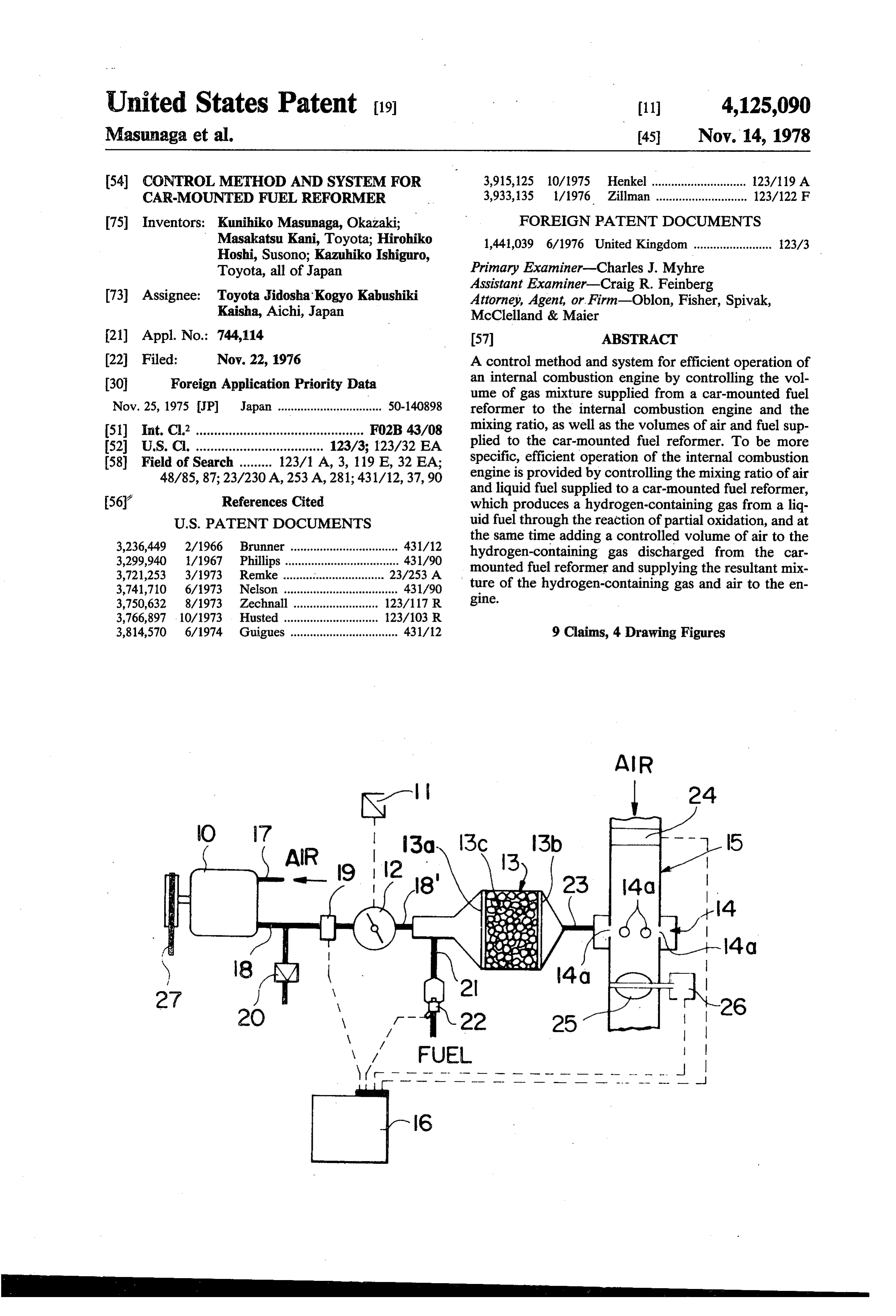
of driving into a corresponding change in volume of the a flowmeter 19 to the valve 12 and has attached thereto air flow into the reformer. a pressure adjustment valve 20. By setting this valve 20 Yet another object of the present invention is to pro at a desired pressure, for instance about 0.6 kg/cm, the vide preferential control of the composition of a reform air pressure in the blower pipe 18 can be desirably ad er-generated gas, thereby preventing undesirable phe- 5 justed. The valve 12 is connected to the air intake of the nomena in the reformer, such as overheating, overcool reformer 13 through a pipe member 18". The liquid fuel ing and carbon segregation. intake of the reformer 13 is connected to a liquid fuel Still another object of the present invention is to supply pipe 21, which is fitted with a blow rate control control the air inflow to a reformer, thereby increasing valve 22, for instance, and electromagnetic valve. A the calorific value per unit volume of the gaseous fuel 10 reformed gas jet pipe 23 at the outlet of the reformer 13 generated in the reformer. is connected to the mixer 14 attached to the air pipe 15. Still another object of the present invention is to The reformed gas goes through the reformed gas jet provide a fine control of a whole reformation system by hole 14a opening provided in air pipe 15 and then into automatically and exactly maintaining the ratio of air the air pipe 15 itself. In the upstream part of the air pipe and fuel supplied to the reformer and the ratio of the 15 15 there is disposed an air flowmeter 24 and in the gaseous fuel generated in the reformer and supplied to downstream part of the air pipe 15 there is disposed a the internal combustion engine and the air drawn there butterfly valve 25. The butterfly valve 25 interlocks into. with a servo-motor 26 for being opened and closed. The Still another object of the present invention is to upstream end of the air pipe 15 connects to an air cause leanburning of a reformed gas from a reformer, 20 cleaner, not shown, while the downstream end connects thereby minimizing the harmful contents in the exhaust to the intake manifold of an internal combustion engine, gas, such as nitrogen oxides and carbon monoxide. also not shown. The flowmeter 19, the flow rate control The foregoing and other objects are attained by the valve 22, the air flowmeter 24 and the servo-meter 26 present invention which provides a control method and are respectively connected to the computer 16. system for swiftly adapting the air/fuel ratio of a re- 25 During the starting phase of the operation of the former and the air/fuel ratio of an internal combustion present invention, air flowmeter 24 generates a signal to engine connected to the reformer, respectively, to the the computer 16 and, in turn, to servo-motor 26 which optimum conditions therefor by converting the driver's serves to open butterfly valve 25 so as to allow for a consciousness of driving output requirements into terms proper secondary air and reformer gas mixing with of a changing air inflow to the reformer. In other 30 introduction into the internal combustion engine for the words, it is so arranged that his consciousness of driving purpose of starting the same. Furthermore, the mixing can be sensitively reflected directly as a rise or fall in the ratio of the reformed gas and the secondary air which volume of air inflow to the reformer. Information on a are supplied into the air pipe 15 can be controlled by rise or fall in the volume of air inflow is processed by a varying the opening degree of the butterfly valve 25, computer to optimize the volume of liquid fuel supplied 35 thus maintaining the total ratio of air and fuel, which are to the reformer and the composition and volume of the fed into the internal combustion engine, at a constant gas mixture drawn into the internal combustion engine. level. Control of the opening degree of butterfly valve
BRIEF DESCRIPTION OF THE DRAWINGS
25 is accomplished by servo-motor 26 as controlled by the computer 16.
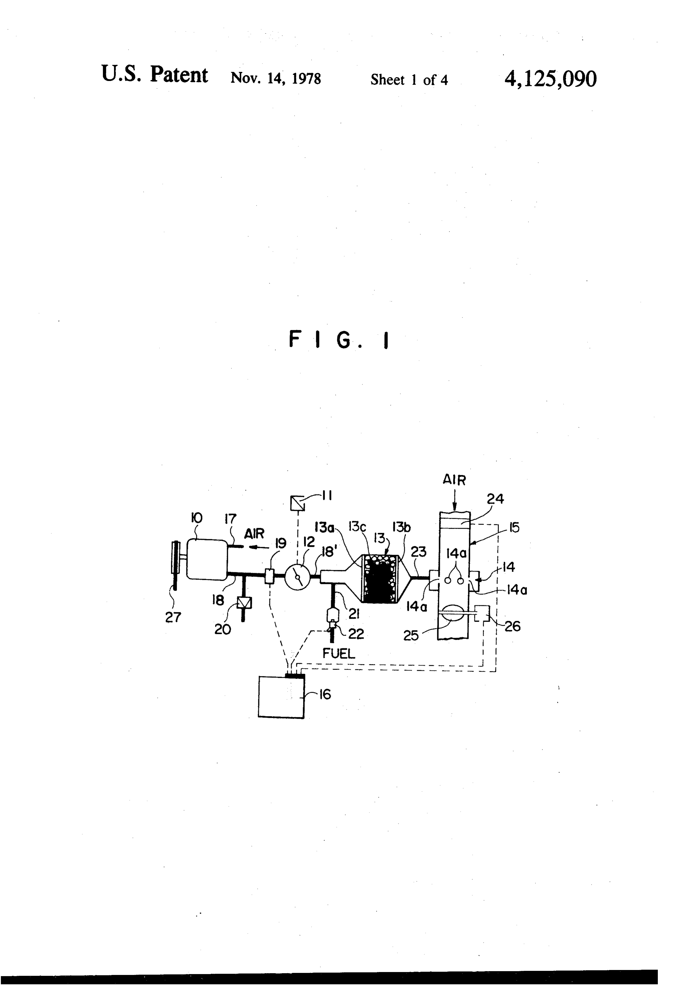
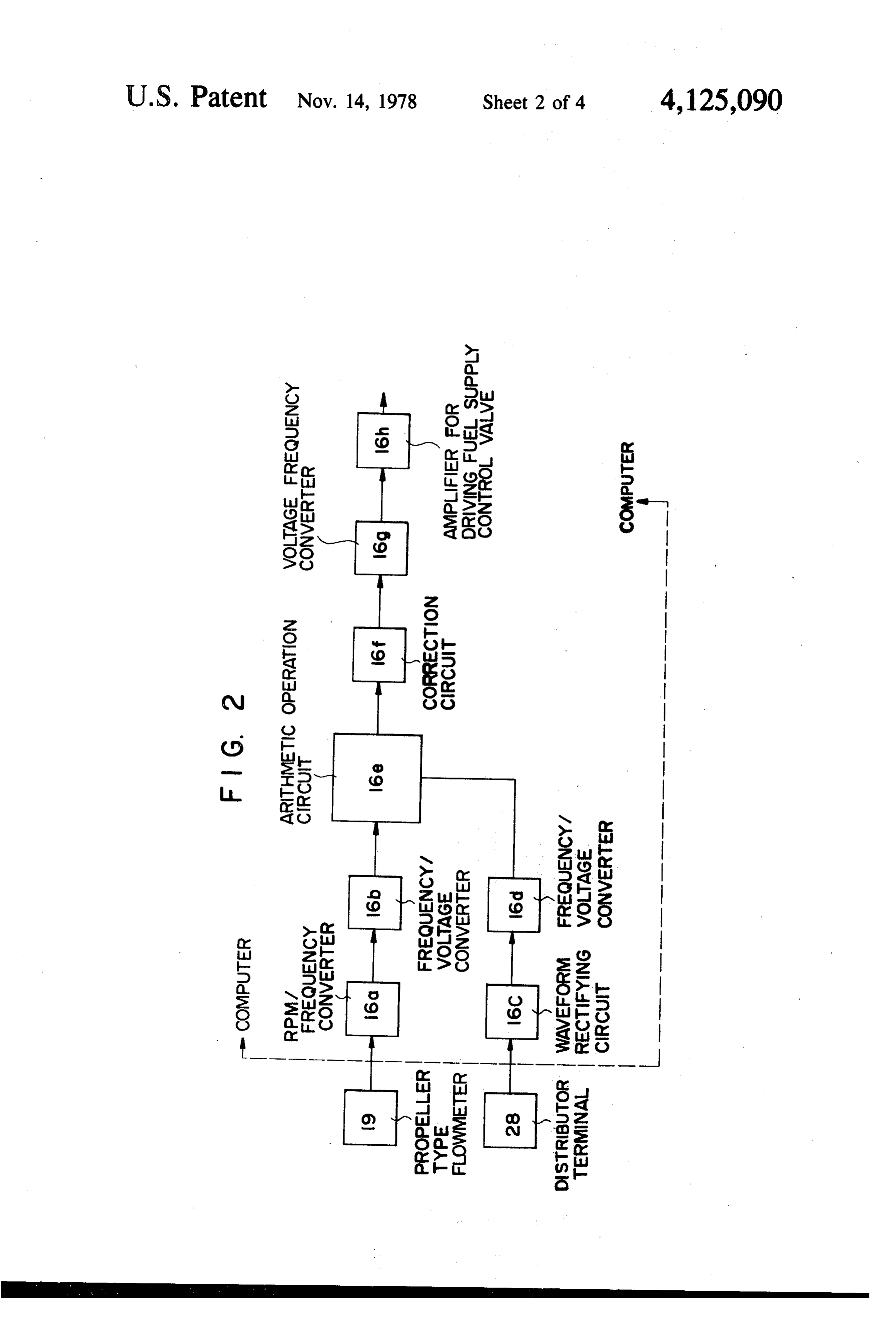
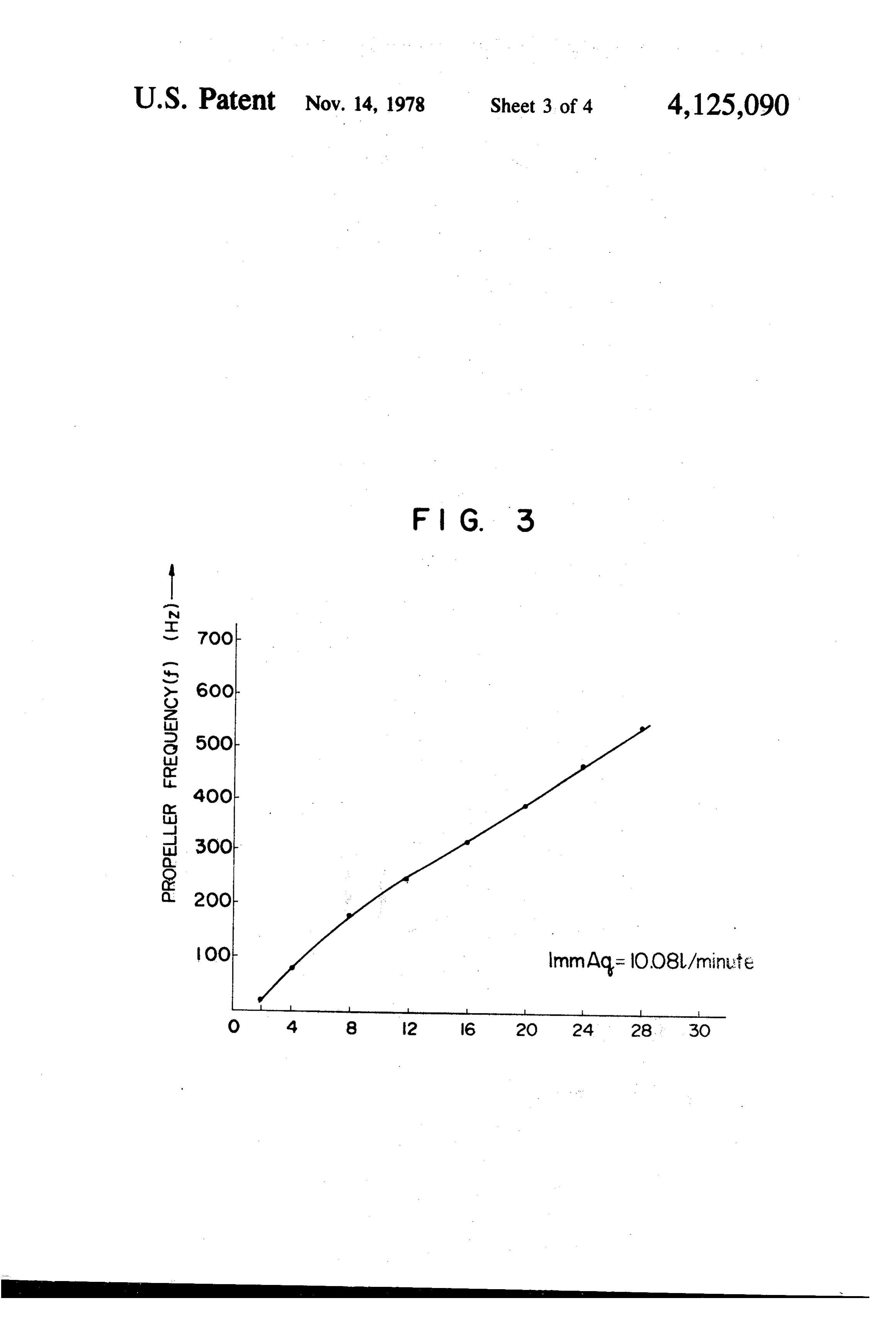
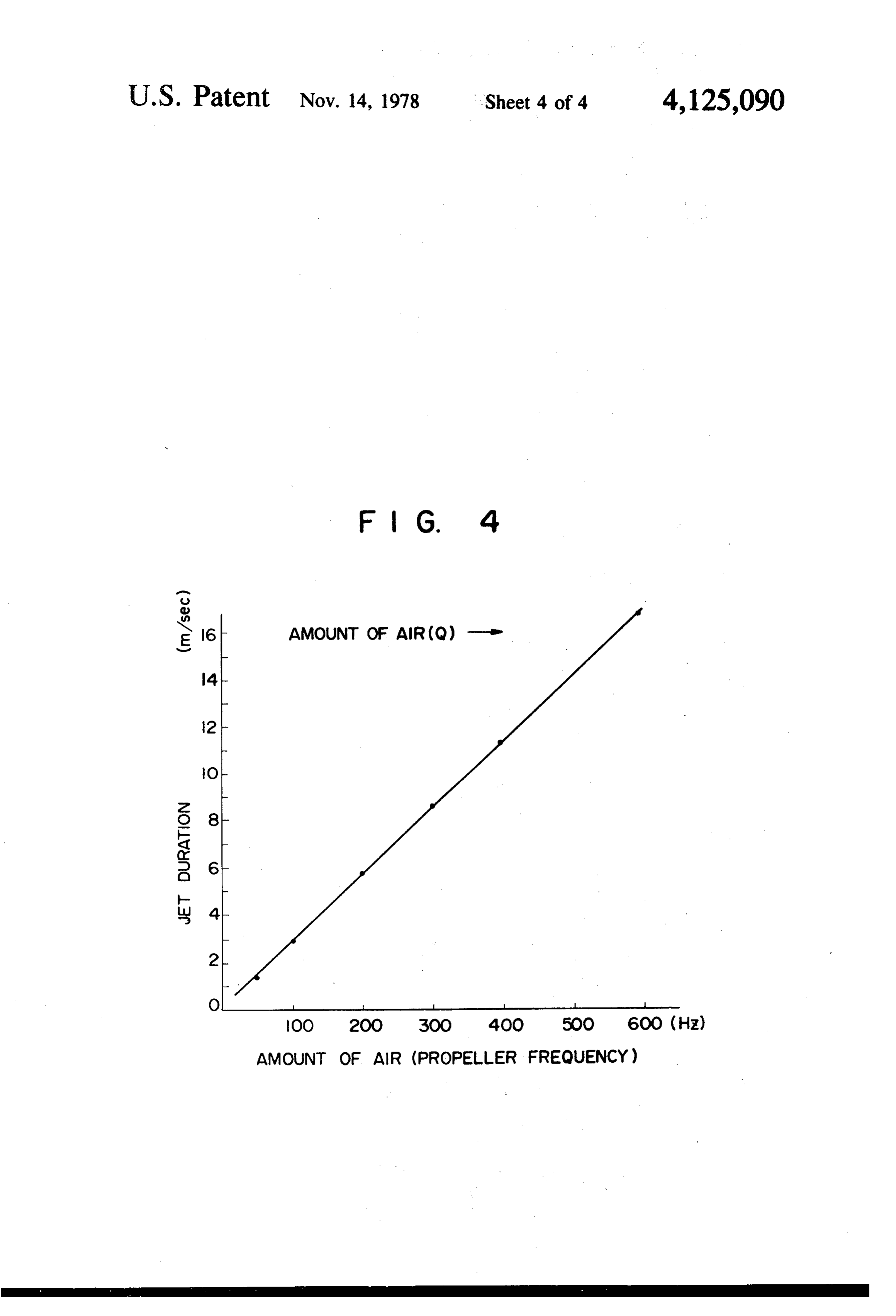
Other objects, features and attendant advantages of 40 At the starting phase of the internal combustion en the present invention will be more fully appreciated as gine, a driver depresses the accelerator pedal 11 to open the same becomes better understood from the following valve 12, thereby introducing air into the reformer 13 description when considered in connection with the through the air pump 10. Then, the volume of air sup accompanying drawings wherein: plied to the reformer 13 is detected by the flow meter 19 FIG. 1 is a schematic view of a preferred embodiment 45 and the thus detective value is transmitted to the com of the present invention; puter 16. The computer 16 controls the control valve 22 FIG. 2 shows a basic configuration of a computer to according to the detected value of the flowmeter 19, be used in the embodiment of the present invention thus adjusting the amount of fuel supplied to the re shown in FIG. 1; former through the control valve 22 to the volume of FIG. 3 is a characteristic diagram illustrating the 50 air supplied to the reformer 13, so as to maintain the relation between the propeller frequency and the drawn air/fuel ratio in the reformer 13 at constant level. The air volume; and amount of the reformed gas generated by the reformer FIG. 4 is a characteristic diagram illustrating the 13 is proportional to the air amount detected by the relation between the jet duration and the propeller fre flowmeter 19.
quency. 55 On the other hand, the amount of the secondary air
DETAILED DESCRIPTION OF THE
detected by the flowmeter 24 is transmitted to the com
PREFERRED EMBODIMENT
puter 16. According to the thus detected value of the secondary air, the computer 16 controls the opening
Referring now to the Drawings, and more particu degree of the butterfly valve 25, thereby maintaining larly to FIG. 1, there is shown a general composition of 60 the total air/fuel ratio of the mixing gas composed of a car-mounted fuel reformer system, the major compo the reformed gas and the secondary air, which are both nents of which are an air pump 10, a valve 12 inter supplied into the air pipe 15, at a constant level. locked mechanically or electrically with an accelerator The reformer 13 may be a conventional one, for in pedal 11, a reformer 13, an air pipe 15 equipped with a stance the one illustrated in FIG. 1, in which a granullar mixer 14, and a computer 16. The air pump 10 compris- 65 catalyst 13c is inserted between two opposed metal ing an air suction pipe 17 and a blower pipe 18 is given screens 13a, 13b. The flowmeter 19 provided midway in a torque via a belt 27 from the internal combustion the blower pipe 18, which is intended for measurement engine, not shown. The blower pipe 18 is connected via of a relatively low flow rate, may be a propeller type
Page 8
flowmeter, but is not limited to being propeller type. In According to the present invention, in which the the propeller type flowmeter 19, a proportional rela whole system is placed under the control of a computer, tion, as illustrated in FIG. 3, holds between the volume fine control is practicable, the exhaust gas can be clean, of air flowing in the blower pipe 18 and the propeller fuel consumption can be decreased, and with the com frequency or rpm. The rpm of the propeller type flow position of the gaseous fuel produced in the reformer meter is fed to the computer 16, which calculates the being preferentially controllable, the reformer can be necessary supply of fuel. The propeller rpm is con maintained at the right temperature and segregation of verted to a frequency signal in an rmp/frequency trans carbon can be prevented.
ducer 16a, shown in FIG. 2, consisting of a radiative The internal combustion engine which burns a gase diode-photo transistor. The frequency signal is then 10 ous fuel, which contains much hydrogen and contains converted to a voltage signal in a frequency/voltage carbon monoxide or methane as the main combustible transducer 16b and the voltage signal goes into an arith element, is more heavily affected by the calorific value metic operation circuit 16e. Meanwhile, the engine rpm of fuel than by the air/fuel ratio. Therefore, according signal from a distributor terminal 28 has its waveform to the present invention, which can swiftly control the rectified in a waveform rectifying circuit 16c and is 15 composition of gaseous fuel, an internal combustion converted to a voltage signal in a frequency/voltage engine can run under different conditions without mis transder 16d, which signal goes into the arithmetic op firing or stopping. Moreover, since the air/fuel ratio can eration circuit 16e. In the arithmetic operation circuit be finely adjusted, the air/fuel ratio can be very 16e, the signal from the propeller type flowmeter 19 is smoothly held at a present value.
divided by the signal from the distributer terminal 28,20
The effect of applying the present invention is illus thereby giving the air flow rate in each revolution of the trated in the following example: engine. From the present diagram of fuel jet duration vs. air volume, the necessary fuel jet duration can be Experimental Conditions found, as illustrated in FIG. 4. The fuel jet duration Road: flat, smooth signal is then sent to a correction circuit 16f, where it is 25 Vehicle: passenger car weighing 1,100 Kg added with various factors to give a more appropriate Internal combustion engine : 1,600 cc 4-cylinder fuel jet duration signal, which is then converted to a Reformer : partial oxidation type frequency signal by a voltage/frequency transducer Catalyst : nickel 16g. The frequency signal is sent to a fuel supply control valve drive amplifier 16h, where it is changed to an 30 Liquid Fuel : non-leaded gasoline output with enough power to drive the fuel flow rate control valve 22. The opening of this valve 22 is set Experimental results depending on this output. When this valve 22 is electro Car speed Output NO Catalyst temp.
Air/fuel ratio in reformer magnetic valve, the open-close timing of the valve will (km/hr) (ps) (ppm) (C) (weight ratio) depend on this output. 35
In operation, the torque of an internal combustion 60 7.2 110 870 4.5 engine, not shown, is directly or indirectly, through a 90 3.8 205 950 3.8 transmission member like belt 27, transmitted to the air pump 10. The primary air supplied from the air pump 10 In the above example, it is designed that with an is set to a desired pressure, as already indicated, by the increased volume of air inflow to the reformer, the pressure adjust valve 20 and this air is introduced air/fuel ratio may gradually drop. As is evident from through the flowmeter 19 and the valve 12 into the the above table, even when the engine rpm rises and the reformer 13. Upon the output control device 11, for load is increased, the NO, content of the exhaust gas is instance the accelerator pedal, being operated by the driver, the valve 12 interlocked therewith acts to con 45 held at a low level and the catalyst temperature is in the trol the flow rate of primary air, increasing the flow rate range of 800 C. - 1,100 C. in which the catalyst can when the output is to be increased. The flow rate of be highly active.
Depending on the structure and material quality of primary air is converted to an electrical signal at the flowmeter 19. When this signal is fed to the computer the reformer practically employed, the air/fuel ratio 16, a control valve, such as the electromagnetic valve 50 should be properly corrected. For instance, the air/fuel ratio under maximum load is restricted by the highest 22, provided in the fuel supply pipe 21, reacts to this allowable signal, thereby controlling the flow rate of liquid fuel temperature of the catalyst or structural ma and supplying the fuel to the reformer 13. At the same terial, the reaction volume, the calorific capacity of the time the flowmeter 24 provided in the air pipe 15 con reformer, etc., while the air/fuel ratio under minimum verts the flow rate of the drawn secondary air to an 55 load is restricted by the lowest allowable reaction tem electrical signal, which is then fed to the computer 16. perature necessary for reforming reaction. Further, the The servo-motor 26 reacts to this signal and causes the air/fuel ratio under medium output is affected by a valve 25 in the air pipe 15 to control the volume of change in the engine output depending on the composi drawn air such that the air/fuel ratio of the gas mixture tion of gaseous fuel produced by reforming and by a supplied to an internal combustion engine, not shown, 60 change in the composition of exhaust gas. Moreover, may settle to a value corresponding to the volume of these air/fuel ratios under maximum and minimum gaseous fuel flowing in through the mixer or venturi 14. loads may be re-corrected.
In this way, the driver can swifly and adequately con As many apparently widely different embodiments of trol the operating condition of the reformer and the this invention may be made without departing from the internal combustion engine by mere operation of the 65 spirit and scope thereof, it is to be understood that output control device, or more simply, the accelerator within the scope of the appended claims the invention pedal. Thus, the practical value of the present invention may be practiced otherwise than as specifically de is extremely high. scribed herein.
Page 9
What is claimed as new and desired to be secured by 5. A control system for a car-mounted fuel reformer Letters Patent of the United States is: comprising:
1. A control method for a car-mounted fuel reformer an air pipe means, including a venturi-tube, which is comprising the steps of: connected to an intake manifold of an internal com adjusting a volume of primary air flowing into a re bustion engine, said air pipe means constituting a former, which produces a hydrogen-containing first flowmeter upstream of the venturi-tube and reformed gas through partial oxidation, and simul having a throttle valve downstream thereof; taneously converting the volume of primary air a reformer connected to said venturi-tube; inflow into a first electric signal; a primary air supply source connected to said re optimizing a supply of liquid fuel to the reformer by 10 former;
means of a computer to which said first electrical a second flowmeter and valve means provided be signal is fed; tween said primary air supply source and said re adjusting the composition and volume of reformed former, said second flowmeter serving to convert gas produced in the reformer, and simultaneously the air flow into a signal; converting a drawn volume of secondary air to be 5 a fuel supply source connected to said reformer; supplied to an internal combustion engine into a an output control device connected to said valve second electrical signal; means and controlling said valve means; and feeding said second electrical signal to said computer; a computer operable in response to the action of the controlling said drawn volume of secondary air by 20 second flowmeter and valve means wherein the said second electrical signal fed to said computer; flow rate of primary air controlled by said output and control device is converted into a signal by said mixing the reformer gas and the secondary air in second flowmeter; the supply of fuel from the appropriate desirable proportions for meeting vari source of the reformer being controlling by said ous driving conditions according to the signals 25 signal, and at the same time, the flow rate of air provided. drawn into the air pipe means being converted into 2. A control method for a car-mounted fuel reformer a signal by said flowmeter of the air pipe means, comprising the steps of: and the opening of a throttle valve being automati adjusting the flow rate of a primary air fed into the cally adjusted in accordance with said last men reformer by means of a first valve which interlocks 30 tioned signal.
with an output control device; 6. A control system for a car-mounted fuel reformer converting the measured flow rate of said primary air as set forth in claim 5, wherein a blower pipe for said into a first electrical signal; primary air is connected to an air pump interlocked determining the injection duration of an injector by with the torque of the internal combustion engine. means of a computer to which said first electrical 35 7. A control system for a car-mounted fuel reformer signal corresponding to said primary air is fed, as set forth in claim 5, wherein said blower pipe is thereby controlling the a volume of liquid fuel equipped with a pressure adjusting valve. supplied to the reformer; 8. A control system for a car-mounted fuel reformer producing mixture gas under a constant air/fuel ratio as set forth in claim 5, wherein said venturi-tube consti by mixing said liquid fuel with said primary air; tutes a mixer.
producing reformed gas from said mixture gas by a 9. A control system for a car-mounted fuel reformer partially oxidizing reaction of said reformer; comprising:
supplying said reformed gas into an air pipe means a primary air supplying device interconnected with connected to an intake manifold producing a mea an internal combustion engine; sured flow rate of secondary air for an internal 45 a reformer connecting to said primary air supplying combustion engine; device and containing a catalyzer; converting the measured flow rate of the secondary air into a second electrical signal; a first flowmeter interconnected between said pri feeding said second electrical signal corresponding to mary air supplying device and said reformer; said secondary air flow rate to said computer; 50 means for converting flow rate of said primary air condinating said flow rates of said primary air, sec measured by said first flowmeter into a first electri ondary air and the supply volume of said liquid fuel cal signal;
of the injector by means of said computer, thereby an output control device;
controlling a second valve disposed in said air pipe valve means, connected between said primary air means by a control signal generated from said com 55 supplying device and said reformer and intercon puter; and nected with the output control device, to adjust mixing said secondary air and said reformed gas, said flow rate of the primary air; which are drawn into said air pipe means by con means for supplying liquid fuel to be mixed with said trolling motion of said second valve, under a con primary air;
stant air/fuel ratio to produce mixing gas. air pipe means including a mixer member connected 3. A control system for a car-mounted fuel reformer with said reformer and connected to an intake as set forth in claim 2, wherein said primary air supply manifold of the internal combustion engine; ing device comprises an air pump means and a pressure a second flowmeter connected to the air pipe means adjustment valve. for measuring flow rate of the secondary air drawn 4. A control system for a car-mounted fuel reformer 65 into said air pipe means; as set forth in claim 2, wherein said mixer comprises a means for converting the flow rate of said secondary venturi means having reformed gas jet holes operatively air measured by said flowmeter into a second elec connected to said reformer. trical signal;
Page 10
second valve means disposed downstream of said air the computer as said first electrical signal and con pipe means and operably interconnected with a trolling said second valve means as a function of servometer;
a computer operable in response to said first and the flow rates of said primary and secondary air second electrical signal and interconnecting said and as a function of the supply volume of said second flowmeter and said servometer for control liquid fuel fed into the computer as said second ling the supply duration of said liquid fuel in accor electrical signal.
dance with said flow rate of the primary air fed into
Provenance
- Collection
- Cited prior art
- Original PDF
- patentimages.storage.googleapis.com →
- Filed
- 1976-11-22
- Pages
- 10
- Method
- pdftotext (the PDF's own text layer) + pdftoppm 300dpi page scans
- Source
- Google Patents bibliographic record
- Granted
- 1978-11-14
- Inventors
- Kunihiko Masunaga; Masakatsu Kani; Hirohiko Hoshi; Kazuhiko Ishiguro; Toyota Jidosha Kogyo KK
- Transcribed from
- patentimages.storage.googleapis.com →