patent · US5857762
Bicycle lighting system and generator
12 January 1999
Page 1 — bibliographic record
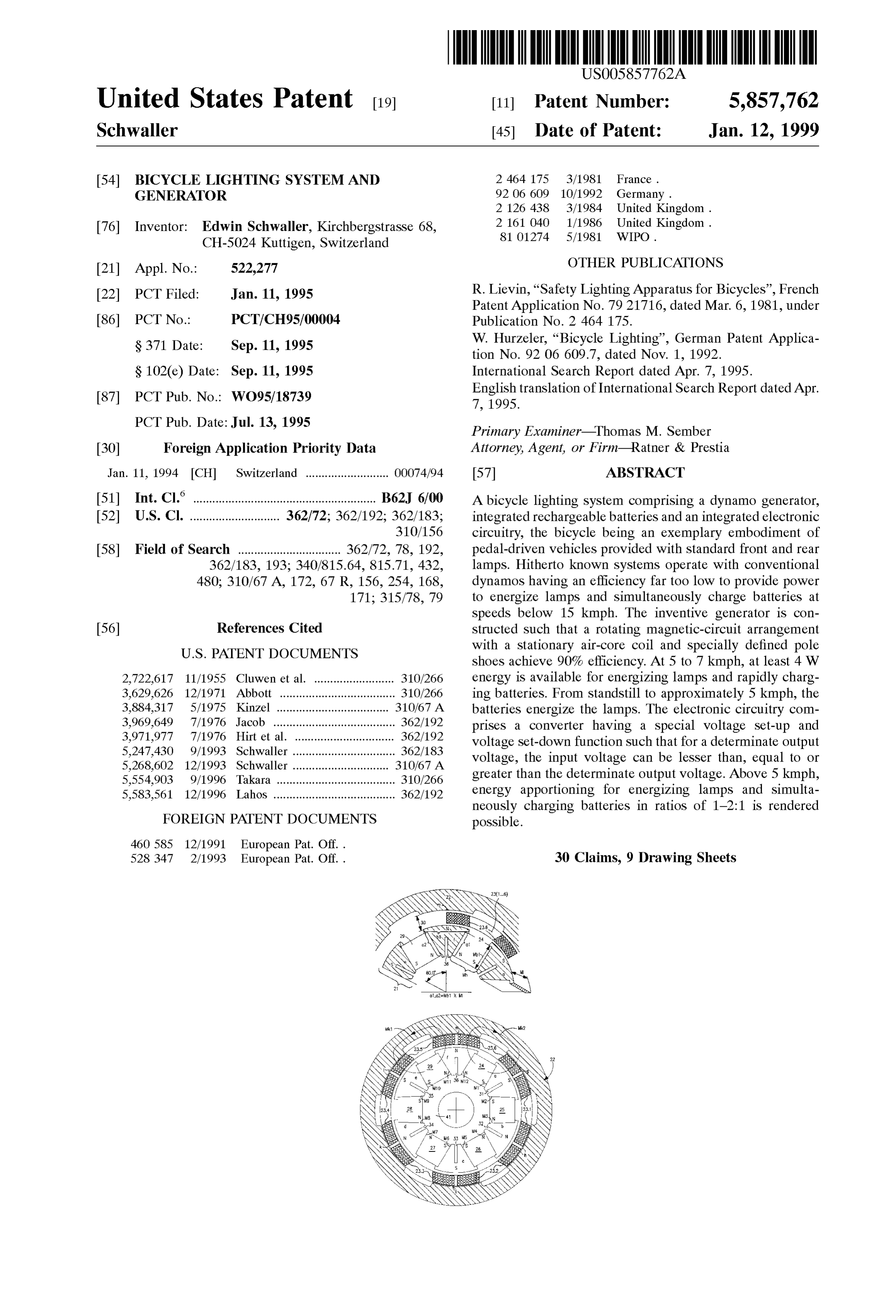
United States Patent (19) 11 Patent Number: 5,857,762 Schwaller (45) Date of Patent: Jan. 12, 1999 54) BICYCLE LIGHTING SYSTEMAND 2 464 175 3/1981 France. GENERATOR 92 06 609 10/1992 Germany.
76 Inventor: Edwin Schwaller, Kirchbergstrasse 68, 2 161040 1/1986 United Kingdom. CH-5024 Kuttigen, Switzerland 81 01274 5/1981 WIPO.
OTHER PUBLICATIONS
22 PCT Filed: Jan. 11, 1995 R. Lievin, “Safety Lighting Apparatus for Bicycles”, French Patent Application No. 7921716, dated Mar. 6, 1981, under 86 PCT No.: PCT/CH95/00004 Publication No. 2 464 175. S371 Date: Sep. 11, 1995 W. Hurzeler, “Bicycle Lighting, German Patent Applica
S 102(e) Date: Sep. 11, 1995 International Search Report dated Apr. 7, 1995. 87 PCT Pub. No.: WO95/18739 English translation of International Search Report dated Apr.
PCT Pub. Date:Jul. 13, 1995 Primary Examiner Thomas M. Sember 30 Foreign Application Priority Data Attorney, Agent, or Firm-Ratner & Prestia Jan. 11, 1994 CH Switzerland .......................... OOO74/94 57 ABSTRACT (51) Int. Cl. ................................................... B62J 6/00 A bicycle lighting System comprising a dynamo generator, 52 U.S. Cl. ............................ 362/72; 362/192; 362/183; integrated rechargeable batteries and an integrated electronic 310/156 circuitry, the bicycle being an exemplary embodiment of 58 Field of Search ................................ 362/72, 78, 192, pedal-driven vehicles provided with standard front and rear 362/183, 193; 340/815.64, 815.71, 432, lamps. Hitherto known Systems operate with conventional 480; 310/67 A, 172, 67 R, 156, 254, 168, dynamos having an efficiency far too low to provide power 171; 315/78, 79 to energize lamps and Simultaneously charge batteries at
Speeds below 15 kmph. The inventive generator is con 56) References Cited Structed Such that a rotating magnetic-circuit arrangement
shoes achieve 90% efficiency. At 5 to 7 kmph, at least 4W 2,722,617 11/1955 Cluwen et al. ......................... 310/266 energy is available for energizing lamps and rapidly charg 3,629,626 12/1971 Abbott ............. ... 310/266 ing batteries. From Standstill to approximately 5 kmph, the 3.884,317 5/1975 Kinzel ... ... 310/67 A batteries energize the lamps. The electronic circuitry com 3.969,649 7/1976 Jacob ....... ... 362/192 prises a converter having a special Voltage Set-up and 3,971,977 7/1976 Hirt et al. . ... 362/192 Voltage Set-down function Such that for a determinate output 5,247,430 9/1993 Schwaller ..... ... 362/183 Voltage, the input Voltage can be lesser than, equal to or 5,268,602 12/1993 Schwaller ..... ... 310/67 A greater than the determinate output Voltage. Above 5 kmph, 5,554,903 9/1996 Takara ...... ... 310/266 5,583,561 12/1996 Lahos ...................................... 362/192 energy apportioning for energizing lamps and Simulta neously charging batteries in ratioS of 1-2:1 is rendered
FOREIGN PATENT DOCUMENTS possible.
528 347 2/1993 European Pat. Off.. 30 Claims, 9 Drawing Sheets
Page 2
Drawing sheet — no readable text.
Page 3
Drawing sheet — no readable text.
Page 4
Drawing sheet — no readable text.
Page 5
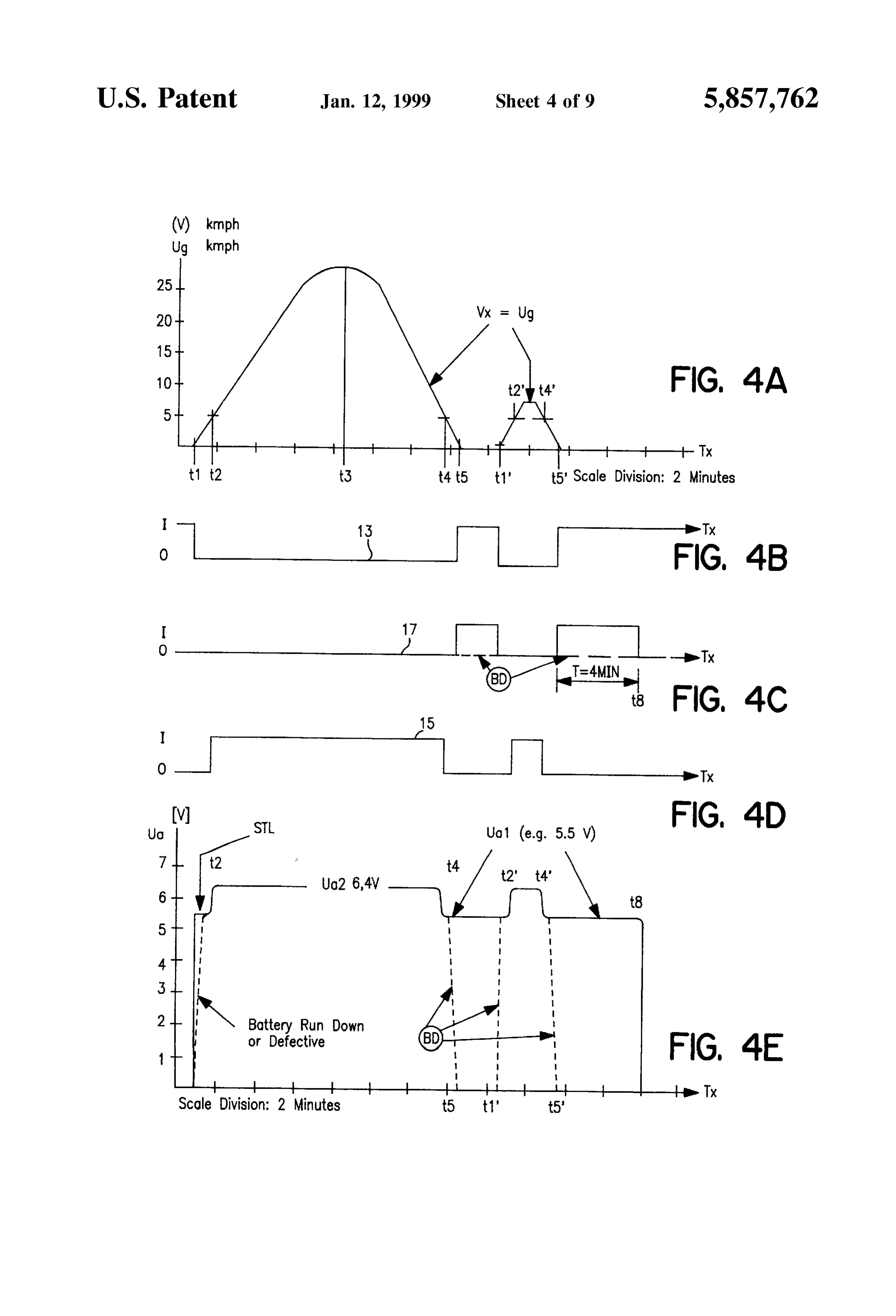
(W) kmph
Ug kmph
10 FIG, 4A
t1 t2 t3 t4 t5 t1' t5" Scale Division: 2 Minutes
O FIG, 4B
O T 4MN -o-Tx
(V) FIG, 4D
Battery Run Down or Defective
FIG, 4E
Page 6
Drawing sheet — no readable text.
Page 7
Drawing sheet — no readable text.
Page 8
Drawing sheet — no readable text.
Page 9
Drawing sheet — no readable text.
Page 10
Drawing sheet — no readable text.
Page 11
BICYCLE LIGHTING SYSTEMAND latest State of advanced engineering and technology and GENERATOR accommodated to present-day requirements.
BACKGROUND OF THE INVENTION
Another Significant object of the present invention is directed to the provision of a new and improved bicycle
The present invention relates to a bicycle lighting System 5 lighting System which is relatively simple in construction comprising a dynamo System drivable by a ridden bicycle and design and, particularly, economical to manufacture. and mounted thereupon, at least one front light or headlamp Yet a further significant object of the present invention is and at least one rear light or tail lamp, both of which are concerned with a new and improved dynamo System, Supplied with electric power from the dynamo System, and which-With regard to construction, power efficiency and an electronic circuitry which converts the electric power production cost thereof—meets all requirements of the produced by the dynamo System into a regulated direct bicycle lighting System of the present invention. current Voltage for the purpose of generating light and The implementation of these and further objects of the charging an accumulator or Storage battery. The invention present invention is based on the finding and conclusion that also relates to a new and improved generator for general 15 a Satisfactory bicycle lighting System can only be realized by applications, particularly however for use as a bicycle means of a dynamo generator having an efficiency consid dynamo generator. erably higher than that of conventional dynamos. Conventional and marketable bicycle lighting Systems The bicycle lighting System of the present development is have to comply, with respect to the electric power and characterized in that the dynamo System is provided with a Voltage, with the Standards determined by law. At a traveling dynamo generator comprising an inner circuit and an outer Speed of 15 kilometers per hour and beyond that, these circuit, both of which are mounted for Synchronous rotation Standards specify a maximum voltage of 7V for the dynamo in the same direction about a Stationary air-core coil con output Voltage applied to the lamps. In accordance with legal Sisting of coil Sections, whereby the inner circuit and the regulations, the minimum value of the output voltage of the outer circuit each comprise n poles in identical pole pitch, So dynamo lies between 3 V at 5 kmph and 5.8 V at 15 kmph 25 that from a minimum traveling Speed of approximately 5 to and-as indicated in FIG. 5a of the annexed drawings 7 kmph the power output of the dynamo System is must not fall short of 5.8 V at a speed beyond or better than adequately high for rapid charging of the rechargeable 15 kmph. On the basis of the aforementioned regulations, accumulator battery and to Simultaneously enable the ener present-day or State-of-the-art dynamos allow producing gization of the bicycle lamps at a high illumination level, merely 1.4 W power at a bicycle traveling speed of 5 to 6 and in that the electronic circuitry comprises a converter kmph. If Such power or output of present-day conventional having a set-up and Set-down mode of operation Such dynamos is increased, it would be physically impossible to that-for a determinate Stabilized output Voltage-the fed meet or observe the legally Specified maximum voltage of 7 input voltage can be lower than, equal to or higher than Said V at 15 kmph or beyond such speed. Only by taking output Voltage, whereby the converter is additionally Sup respective load measures would it be possible to prevent 35 plied from the rechargeable accumulator battery as long as exceeding the legally Specified maximum value. As a result, the traveling Speed falls short of Said minimum traveling the power dissipation or loSS would greatly increase and the speed of about 5 to 7 kmph.
efficiency would then considerably decrease. In order to ensure the required characteristic features and Therefore, conventional bicycle lighting Systems cannot properties of the dynamo System, the generator has a high be additionally loaded in the lower Speed range for the 40 efficiency and a very low coil internal resistance, So that at purpose of charging a rechargeable accumulator battery. the minimum traveling speed the output is at least 4.5 W at Only from a traveling Speed of approximately 15 kmph, a relatively low output Voltage. The output of the dynamo conventional dynamos will generate Sufficient power that generator is thereby converted into an output voltage of 6.2 could be used for charging the rechargeable accumulator V to 7 V.
battery, the efficiency of these known Systems being 45 The inner circuit comprises n (preferably six by way of extremely low when the traveling speed is below the afore example) inner pole shoes, and at each inner pole shoe there mentioned Speed of 15 kmph. Laterally mounted dynamos are laterally arranged two magnetic poles in homopolar have an efficiency of approximately 17% to 24%, roller configuration. In this manner, the two magnetic Surfaces dynamos can achieve an efficiency of 30% to 35% at the project themselves upon the pole-shoe Surface. Since the most, and the efficiency of hub dynamos is approximately 50 two magnetic Surfaces are preferably far larger than the 40%. When the traveling speed of the bicycle exceeds 15 pole-shoe Surface, the density of the magnetic flux corre kmph, the efficiency additionally decreases because of the spondingly increases toward the pole-shoe Surface. This power draw or consumption while charging the accumulator arrangement is advantageous in that these inner pole shoes battery. Under Such circumstances, the bicycle rider is possess a relatively Small mass and thereby render possible obliged to expend additional physical energy for actuating 55 a Substantial weight reduction.
the dynamo. The Outer circuit comprises n (preferably six by way of Those skilled in the art have criticized the aforementioned example) outer pole shoes which are oppositely arranged limitations and drawbacks of prior-art constructions and relative to the n inner pole Shoes and nose-shapedly pro have realized that conventional dynamos and bicycle light jecting toward the latter, these outer pole shoes being ing Systems do not correspond at all with the State of 60 Structured Such that each air gap between the inner pole present-day engineering knowledge. shoes and the respective Outer pole shoes assigned to the
SUMMARY OF THE INVENTION
latter is the shortest path for the magnetic flux. In this manner, the magnetic leakage flux is advantageously
Therefore, with the foregoing in mind, it is a primary reduced.
object of the present invention to provide a new and 65 In order to reduce the mutual interference of the two improved construction of a bicycle lighting System in com homopolar magnets laterally lying against their respective bination with a generator, which System is adapted to the inner pole shoe, each inner pole shoe is divided in the middle
Page 12
or mid-portion thereof into two identical parts by a slot invariably between 4W and 6 W, advantageously between providing an air gap extending in the radial direction. This 4.5W and 5 W. In this manner, the short-circuit safety of the arrangement results in the additional advantage of a Smaller accumulator battery and of the dynamo generator as well as pole-shoe Volume as well as larger magnet heights or, in of the entire dynamo System is ensured. other words, two half magnet-lengths per pole together with According to a particularly preferred embodiment of the the Smallest magnet-volume and double magnet-Surface are present invention, the electronic circuitry further comprises possible.
The air gap in the inner pole shoes reduces the mutual (a) a rectifier circuit for the purpose of producing the aforesaid rectified and Smoothed dynamo output Voltage interference of the two homopolar magnet faces because the which is Supplied magnetic flux glides in each case with respective halves over limiting device, (b) toa first the Voltage-converting and energy the pole shoe to the outer circuit. The two magnetic fluxes purpose of converting a firstvoltage divider network for the rectified and Speed-proportional in each inner pole Shoe possess an optimally short magnetic output voltage of the dynamo circuit path, So that there results an optimal magnetic flux. A nent Voltage and applying Suchgeneratorfirst into a first compo component Voltage to a further advantage is seen in the fact that an extremely Small generator with very high flux densities can be produced, 15 first threshold-value Switch corresponding with the afore Such generator having at the same time a light-weight, Small mentioned threshold-value device, (c) a second Voltage magnet-volume and high-efficiency Structure. The efficiency dividerand network for the purpose of converting the rectified
Speed-proportional output voltage of the dynamogen achievable by means of the new and improved generator provided for the bicycle lighting System constructed accord erator into a Second component Voltage and applying Such ing to the present invention is at least approximately 90%. Second component Voltage to a Second threshold-value In a preferred embodiment of the dynamo System accord battery Switch, whereby the first threshold-value switch applies the ing to the present invention, the converter of the electronic limiting devicevoltage to the Voltage-converting and energy circuitry comprises a voltage-converting and energy the rectified output by means of Said electronic Switchgear when limiting device for converting the input Voltage into a erator exceeds a firstVoltage Supplied from the dynamogen threshold Voltage corresponding with determinate Stabilized output Voltage and for limiting the 25 Said determinate minimum voltage converted energy to a determinate maximum power output. threshold-value Switch, and wherebyandthedetected second by the first threshold
The electronic circuitry further comprises a threshold-value value Switch transmits to the Voltage-converting and device which detects a rectified and Smoothed output limiting device a signal for Switching over the output energy Voltage, whereby in case the threshold-value device detects of the latter from the first stabilized output voltagevoltage to the that a determinate minimum voltage of the dynamo genera Second Stabilized output Voltage, and Vice versa, whenever tor is exceeded, the Voltage Supplied from the accumulator the Second threshold-value Switch detects that a Second battery is fed by means of an electronic Switchgear-in threshold Voltage is not reached or is exceeded, (d) a delay addition to the rectified and Smoothed dynamo output circuit connected to the output of the first threshold-value Voltage-to the Voltage-converting and energy-limiting device. During battery operation, the output Voltage of the 35 Switch as well as to the electronic Switchgear and which—in Voltage-converting and energy-limiting device lies within a case the rectified and Smoothed output voltage of the first constant output voltage range. During dynamo dynamo opens the generator falls short of the first threshold Voltage electronic Switchgear at the end of a predeter operation, the output voltage of the Voltage-converting and mined period of time, e.g. four minutes, for the purpose of energy-limiting device lies within a Second constant output Switching off the Voltage of the accumulator battery from the Voltage range, the latter lying above the first constant output 40 input of the Voltage-converting and energy-limiting device, Voltage range. The electronic circuitry further comprises a and (e) the aforementioned battery charging device which is battery charging device which is activated above an output output coupled to the Voltage-converting charging Voltage lying between the first constant output limiting device and which—also in the caseandof energy battery Voltage range and the Second constant output voltage range. operation-remains activated for charging the battery. The first constant output voltage range of the electronic 45 circuitry preferably lies within a fixedly set range from 4.5 The first threshold-value Switch Switches on, by means of V to 6 V. During this mode of operation, the input voltage Voltage the electronic Switchgear, the battery voltage at a threshold range of the converter lies between 0.8 V minimum operatesofatapproximately an output 0.8 V. The battery charging device voltage of 6.1 V up to maximum 7 V, threshold-value Voltage and a maximum Switch-over Voltage Such output Voltage proportionally increasing with higher of 4.8 V. 50 power
The Second constant output Voltage range of the electronic the battery. conversion depending on the charging condition of circuitry preferably lies within a range between 6.2 V and 7
V, but lies preferably above 6.4 V. During this mode of By way of example, the thereby resulting effective or operation, the input Voltage range of the converter lies actual efficiency of the entire bicycle lighting System con between approximately 5 V in an initial Speed range and a 55 structed according to the invention for 3W luminous power maximum voltage level of 80 V at a speed of about 80 kmph. and 1 W battery charging energy is—with reference to 3 By virtue of this Setting of the electronic circuitry in accor W-approximately 60% in the case of a discharged accu dance with the teachings of the present invention, the legal mulator battery and approximately 80% in the case of a requirements and Standards are ideally met at each and charged accumulator battery.
every bicycle traveling Speed. The combination of a pow 60 AS alluded to above, the invention is not only concerned erful high-efficiency dynamo generator with the electronic with the bicycle lighting System, but also relates to the new circuitry and the rechargeable accumulator battery renders and improved construction of the generator. Those skilled in possible a combined travel-light, battery-charging and the art will readily understand that the underlying principles Standstill-light System. The electronic circuitry is operated and concepts of the dynamo generator can be also employed by the battery as well as directly by the dynamo generator. 65 for other generator applications.
The Voltage-converting and energy-limiting device pref The inventive generator with a coil arrangement and a erably limits the output power of the electronic circuitry thereto movable arrangement with magnets is manifested,
Page 13
S 6 among other things, by the features that the movable Structed according to the present invention and realized by arrangement comprises an inner circuit and an outer circuit, means of a customized, Solid-State and integrated Switching both of which are mounted for synchronous rotation in the circuit (ASIC);
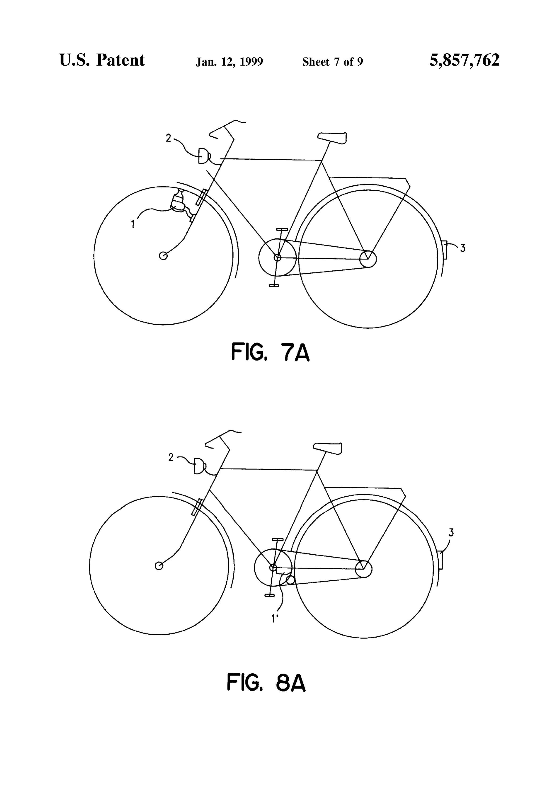
Same direction about a Stationary air-core coil consisting of FIG. 7a Schematically shows a bicycle incorporating a coil Sections, whereby the inner circuit and the Outer circuit Side dynamo with conventional front and rear lamps, each comprise n poles in identical pole pitch. FIG. 7b shows a longitudinal sectional view of a first Advantageously, the inner circuit comprises n inner pole exemplary embodiment of the dynamo System constructed shoes, whereby at each of these inner pole Shoes there are according to the present invention and Structured as a side or laterally arranged two magnetic poles in homopolar laterally mounted dynamo;
configuration, and the outer circuit comprises in Outer pole FIG. 8a Schematically shows a bicycle incorporating a shoes which lie opposite to the inner pole shoes and which roller dynamo with conventional lamps, and nose-shapedly project to the latter, the outer pole shoes being FIG. 8b shows a longitudinal sectional view of a second Structured Such, that each air gap between the inner pole exemplary shoes and the respective Outer pole shoes is the Shortest path according toembodiment the present of the dynamo System constructed invention and Structured as a roller for the magnetic flux. 15 dynamo.
Preferably, each inner pole shoe of the inner circuit comprises in the centric portion thereof a Slot extending in DETAILED DESCRIPTION OF THE radial direction and forming an air gap in order to reduce PREFERRED EMBODIMENTS mutual interference of the respective two magnets laterally lying upon the related inner pole shoe. Furthermore, the Sum to Describing
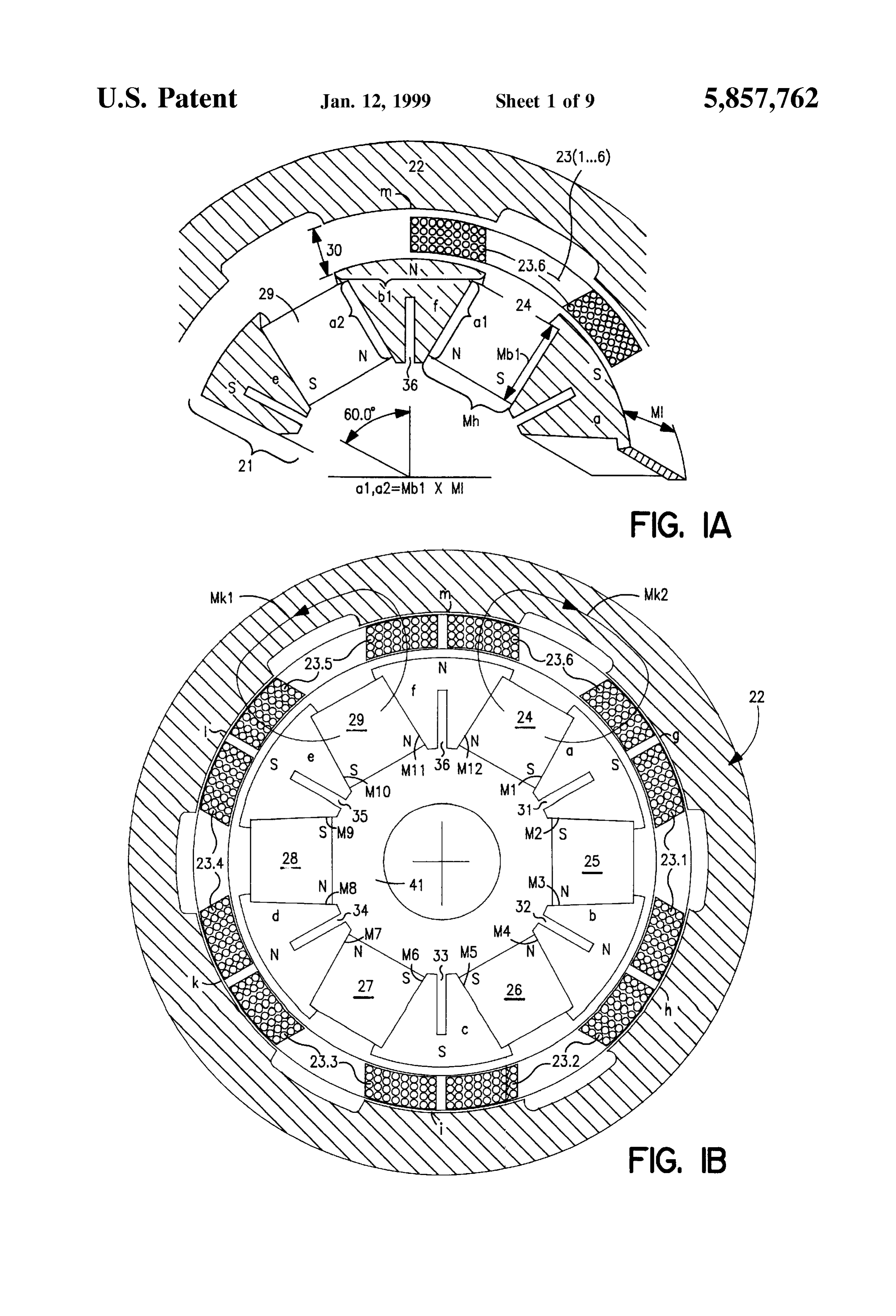
Simplify the now the drawings, it is to be understood that showing thereof, only enough of the con of the two magnet Surfaces adjacent to the related inner pole Struction of the exemplary embodiment of the bicycle light shoe is larger than the peripheral Surface of Said related inner ing System and generator has been illustrated therein as is pole shoe. needed to enable one skilled in the art to readily understand The air-core coil is divided per pole field into two the underlying principles and concepts of this invention. identical coil Sections pole-correctly connected in Series. 25 Turning attention now specifically to FIGS. 1a and 1b of Those skilled in the art will readily understand that the the drawings, a dynamo generator 1 illustrated therein by characteristics of the magnet arrangement and of the mag way of example and not limitation will be seen to comprise netic circuit Structure can be advantageously applied to and in concentric arrangement from the center to the circumfer used for electric motors, for instance, Servomotors. ence a rotating inner circuit 21, a Stationary air-core coil 23 BRIEF DESCRIPTION OF THE DRAWINGS and an outer circuit 22 synchronously rotating with the inner The invention will be better understood and objects other circuit 21. In the exemplary embodiment depicted in FIGS. than those set forth above will become apparent when comprise 1a and 1b, the inner circuit 21 and the outer circuit 22 each consideration is given to the following detailed description Six poles in identical pole pitch, the poles of the inner thereof. Such description makes reference to the annexed outer circuit 22, 35 circuit 21 thereby facing the respective poles of the drawings wherein throughout the various figures of these So that the resulting pole-pitch angle is 60. drawings, there have been generally used the same reference The six poles of the inner circuit 21 are structured in the characters to denote the same or analogous components and the form of Six pole shoes a, b, c, d, e and f, while the poles of wherein: outer circuit 22 are structured in the form of likewise six FIG. 1a is an enlarged detail showing of a part of a 40 the polepole Shoes g, h, i, k, l and m which are situated opposite to croSS-Sectional view of a dynamo generator illustrated in the latter,shoes a-f and which nose-shapedly project toward So that a Smallest possible air gap 30 is formed.
FIG. 1b,
FIG. 1b shows a cross-sectional view of a preferred The pole shoes a-f of the inner circuit 21 are made of soft exemplary embodiment of the dynamo generator con 45 circuitwhile iron, the carrier or Support of the inner magnetic is itself non-ferrous. The outer circuit 22 consists
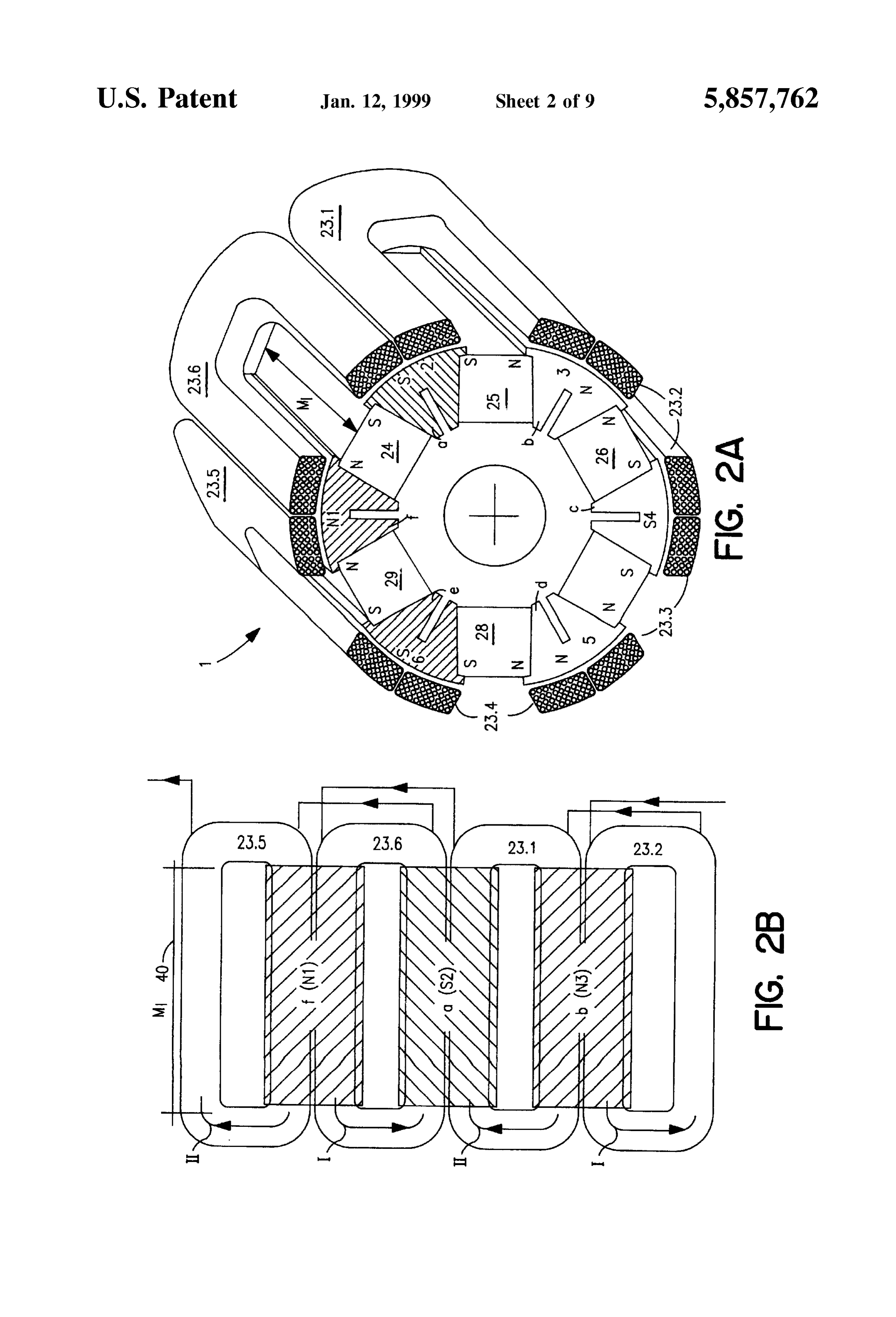
Structed in accordance with the present invention; entirely of Soft iron. The number of poles, namely six, is FIG. 2a Shows the inner magnetic circuit arrangement in Specified only by way of a preferred example. a perspective cross-sectional illustration;
FIG.2b shows the arrangment of the stationary coil in a areBetween the six pole shoes a-fof the inner circuit 21 there arranged six permanent magnets 24–29 in Such a manner
Stretched illustration of the coil arrangement; 50 that in each case they rest homopolar against both sides of FIG. 3 schematically shows a block diagram of a pre each pole Shoe. The result is that the two magnet Surfaces, ferred exemplary embodiment of the bicycle lighting System which in Fig. 1a are designated by reference characters a constructed according to the present invention whereby, in and a (magnet width) at the respective magnets 24 and 29, particular, the role of the proposed electronic circuitry project themselves upon a pole-shoe Surface b of the becomes apparent; 55 respective pole shoe f. The magnet lengths M (refer to FIG. FIG. 4a shows a Voltage--speed/variation-in-time dia 2a) of the permanent magnets 24-29 extending perpendicu gram; and larly with respect to the illustration in FIGS. 1a and 1b and FIGS. 4b, 4c, 4d and 4e depict voltage/time diagrams for the entire arrangement are determined Such, that in each case the purpose of explaining the function of the bicycle lighting the Sum of the respective magnet Surfaces a and a is far System according to the present invention; 60 larger than the respective pole-shoe Surface b. In this FIGS. 5a, 5b and 5c show voltage/speed diagrams to manner, the magnetic-flux density correspondingly further explain the function of the inventive dynamo System, increases toward the pole-shoe Surface b. This arrangement whereby FIG. 5a depicts operation with a discharged or is furthermore advantageous in that the Six pole shoes a-f of defective accumulator battery and FIG. 5c refers to opera the inner circuit 21 possess a relatively Small mass, So that tion with a normal functioning accumulator battery; 65 a Substantial weight reduction is rendered possible. FIG. 6 shows an exemplary accomplished embodiment of However, the entire rotating part of the dynamo generator the electronic circuitry of the bicycle lighting System con 1 possesses, mainly because of the rotating Outer circuit 22,
Page 14
a relatively high moment of inertia, So that the wheel plug-in component. This type of construction renders pos Slippage behavior is Substantially improved. Sible that the electronic part can be plugged in directly at the The magnetic flux from the pole shoes a-f of the inner housing bottom of the dynamo System. A further wiring is circuit 21 is divided across the respective nose-shapedly thus unnecessary. The wires of the Stationary air-core coil projecting pole shoes g-m of the Outer circuit 22 into two have been previously processed and require no Subsequent parts or portions as illustrated in FIG. 1b and designated by treatment or refinishing.
the reference characters MK1 and MK2. By virtue of the The process described hereinbefore renders possible a nose-shaped form of the pole shoes g-m of the outer circuit Stationary air-core coil 23 comprising a very low inductance, 22, Such form being also adapted to the periphery of the coil, i.e. preferably lower than 150 uH. In this manner, there is there results the air gap 30-indicated between a pole-shoe produced a negligible counter inductance by which the pole pair, namely the pole shoes f and m in FIG. 1a-as the sensitivity is hardly or not at all noticeable. The coil resis tance is preferably smaller than 1.6 ohms whereby-in the
Shortest path for the magnetic flux. The magnetic leakage case of an actually accomplished construction of the dynamo flux is thus reduced. generator 1-a resulting magnetic loading was larger than In order to reduce interaction of the homopolar magnets 15 0.6T. In this realized construction the average coil diameter 24-29 resting against both sides of the respective pole Shoes was 31 mm, the magnet length 30 mm and the outer diameter a-f of the inner circuit 21, these pole shoes a-fare provided approximately 44 mm. The present invention aims at pro each with a slot in the mid-portion thereof, Such slots Viding a shorter coil length of approximately 20 mm. Such forming radial air gaps 31-36. The advantage of this coil length has been designated by reference character 40 in arrangement is seen in a Small pole-shoe Volume in View of FIG.2b as well as in FIG. 7. By virtue of this shorter coil coincident large magnet heights. i.e. two magnet widths per length it is possible to also improve the essential inventive energy and power characteristics of the dynamo generator 1 pole with coincidentally the Smallest magnet Volume and the constructed double magnet-Surface. in accordance with the invention. The radial gaps 31-36 provided in the pole shoes a-f of the dynamo had
Having now the benefit of the foregoing description generator 1 as considered with respect to prevent interaction of the two homopolar magnet-face 25 FIGS. 1a, 1b, 2a and 2b, the
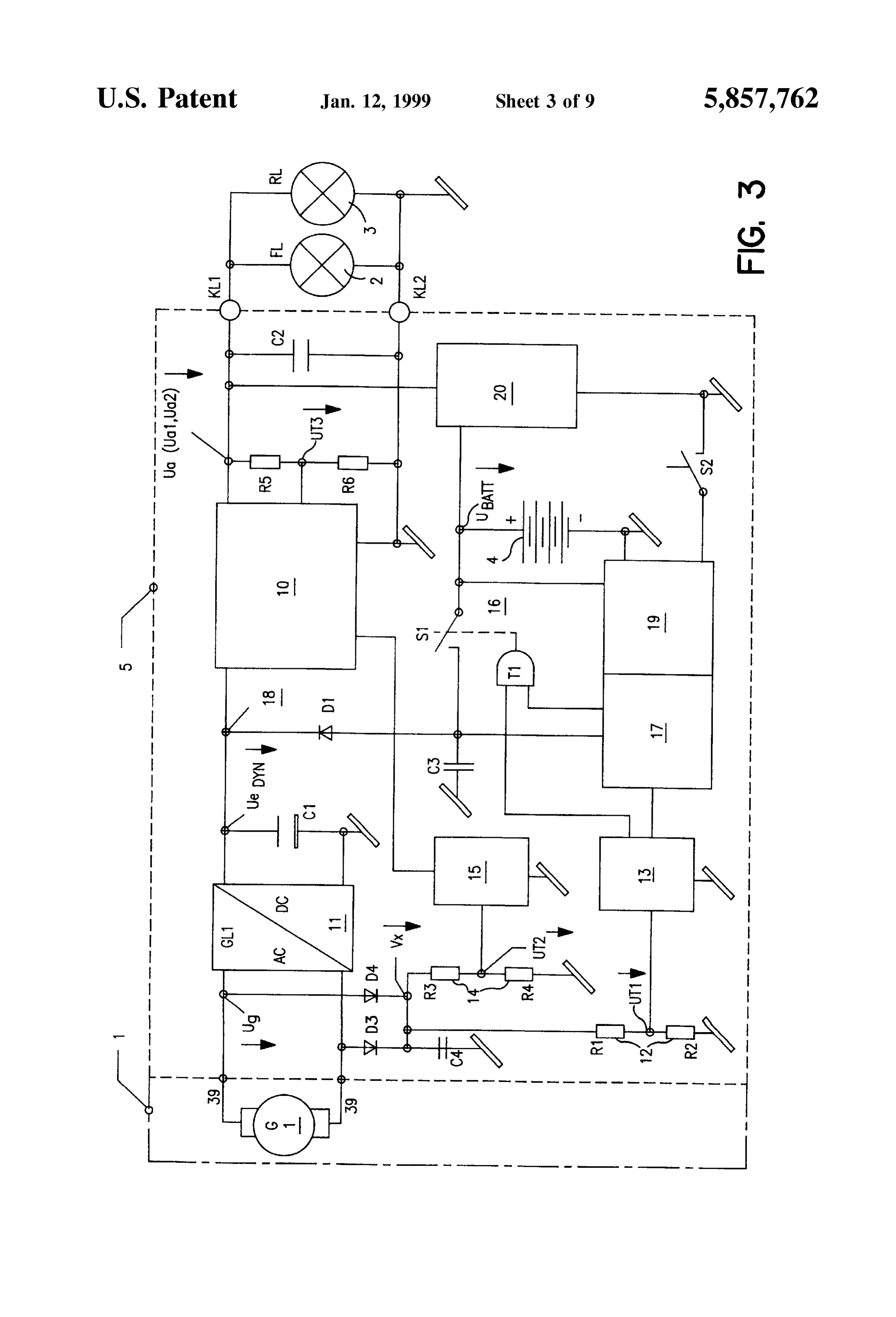
Surfaces, Since the magnetic flux flows in halves through the operation of the entire bicycleconstruction and the mode of lighting System and particu respective pole Shoe of the inner circuit 21 to the respective larly of a preferred embodiment of an electronic circuitry 5 pole shoe of the Outer circuit 22. The two magnetic-flux will be now explained by referring to FIGS. 3, 4 and 5. halves in each of the pole shoes a-fhave an optimally short FIG. 3 illustrates a block diagram of the electronic cir magnetic circuit path MK1 and MK2 depicted in FIG. 1b. cuitry 5 of a preferred exemplary embodiment of the bicycle The result is an optimal magnetic flux. A further advantage lighting System constructed in accordance with the inven is that, in this manner, a relatively Small dynamo generator tion. The electric alternating Voltage produced by the 1 with extremely high flux density, low weight, Small magnet Volume, homogeneous magnetic loading and a very dynamo manner generator 1 constructed in the foregoing described is rectified by a rectifier 11 and smoothed by a high efficiency can be realized. 35 capacitor C. At a circuit node 18 there is formed the sum of FIG.2a illustrates the inner magnetic circuit as well as the a rectified dynamo Voltage Uy and a battery Voltage coil arrangement of the preferred embodiment of the UA as will be hereinafter described. The combined volt dynamo generator 1 in a perspective cross-sectional view. In age Uy and UA produced at the circuit node 18 is FIG.2b there is shown in a stretched or unfolded arrange applied to the inputside of a Voltage-converting and energy ment a Segment of the wire-wound coil in the Sequence 23.2, 40 limiting device 10 which converts this voltage (power) to 6 23.1, 23.6 and 23.5, which together with the pole shoes b, a, V and 6.4 V, respectively. This Voltage-converting and fande form pole fields N3, S2 and N1. The coil connections energy-limiting device 10 possesses the characteristic fea and two winding directions I and II of the coil sections 23.2, ture of optimally adapting itself to the internal resistance of 23.1, 23.6 and 23.5 are schematically indicated in FIG.2b. the dynamo generator 1. In the case of a low input voltage Since normally one coil is guided over two heteropolar 45 due to a low traveling Speed, the Voltage-converting and poles, three coils are required for a six-polar arrangement energy-limiting device 10 Sets up the resulting Voltage not particularly illustrated in the drawings. In this manner, (power). In the case of a higher traveling speed and thus of the Stationary air-core coil arrangement 23, generally rep a high output Voltage and output power of the dynamo resented by reference character 23(1 . . . 6) in FIG. 1a, is generator 1, the Voltage-converting and energy-limiting divided per pole field into two identical coil Sections, So that 50 device 10 sets down the voltage available at the circuit node there are six coil sections 23.1-23.6 pole-correctly con 18 to preferably 6.4 V at an output side U and keeps this nected in Series. There is thus achieved a Substantially Voltage Substantially constant or Stabilized with a variation smaller overall height. As depicted in FIGS. 1a and 1b, there range of approximately +10 mV. By virtue of the provision are provided six coil Sections 23.1-23.6 mutually arranged and application of electronic components representing the at an angular pitch of 60. 55 latest State of the art, Such as Schottky diodes and power In order to fabricate the firm Stationary air-core coil or coil FETs (field effect transistors), there can be achieved an arrangement 23, the windings consisting of backlack copper efficiency of 85% and even better for the voltage-converting wire are wound in Self-contained manner and bent onto the and energy-limiting device 10. This efficiency is about 85% reference circle of the air-core coil arrangement. The coils in the case of low voltages, but can lie above 90% when are inserted in a Suitable plastic injection molding die. The 60 there are relatively high input Voltages, e.g. about 9 V, at the mutual coil connections are already connected and mounted circuit node 18.
at a connection pin plug shown, for instance, in FIG. 7 and The overall functioning and performance of the electronic designated by reference character 39. The plastic injection circuitry 5 will be better understood when consideration is molding die includes at the same time a housing base or now given to the function and mode of operation of a first bottom shown, for instance, in FIG. 7 and designated by 65 threshold-value Switch 13, a second threshold-value Switch reference character 37. Subsequently, the whole unit is 15, as well as a delay circuit 17 and a battery monitoring injection molded with plastic material to form a leadleSS circuit 19.
Page 15
FIRST THRESHOLD-VALUE SWITCH 13 operation. It is furthermore ensured that the Voltage does not The output Voltage of the dynamo generator 1 is rectified fall below 6 V when the energy of the dynamo generator 1 is insufficient.
by means of a rectifier consisting of two diodes D and D. At the output of the Voltage-converting and energy and Smoothed by a capacitor C. This voltage V is propor limiting device 10 there is connected a resistance Voltage tional to the traveling Speed. It is divided by means of a first divider Rs, R, which Supplies a control signal U for the voltage divider 12, which consists of two resistors R and control of the output voltage U (feedback). This control R, and applied as Voltage U to the input of the first voltage is influenced by the second threshold-value Switch threshold-value Switch 13. This first threshold-value Switch 15.
13 activates a gate circuit T at an input voltage higher than The functioning and mode of operation of the electronic V=0.8 V. This means that, by means of the gate circuit T, circuitry 5 schematically illustrated in FIG. 3 will be dis the Voltage of an accumulator battery 4 is Supplied to the cussed more fully hereinafter, particularly in conjunction Summing circuit node 18 by means of a Switch S of an with the description of FIGS. 4a to 4e and FIGS. 5a to 5c. electronic Switchgear 16 and via a protective diode D. A FIGS. 4a to 4e Schematically show in graphical represen further output of the first threshold-value Switch 13 sets the 15 tation the chronological dependence of the voltages U. delay circuit 17 to Zero (static). (approx. V.), Ur and U2 (a component Voltage of the If the input voltage at the first threshold-value Switch 13 voltage V), which are respectively produced by the first is lower than V=0.8 V, the delay circuit 17 is started. The voltage divider 12 and the second voltage divider 14 and latter comprises an oscillator and counting chains which are which are applied to the first threshold-value Switch 13 and here not particularly illustrated. The battery Voltage remains the second threshold-value Switch 15, respectively. The available at the Summing circuit node 18 by means of the approximately linear and Speed-proportional dependence of gate circuit t, the electronic Switchgear 16 and the protec these Voltages is thereby assumed Such that they rise from tive diode D until the output of the delay circuit 17 opens Zero starting at a moment of time t1(t1) up to a moment of the electronic Switchgear 16 by means of the gate circuit T. time t3(t3') in accordance with an assumed increase in Speed The battery voltage is then cut off. The gate circuit T is thus 25 from Zero to 30 kmph, and then again drop approximately activated with the first threshold-value Switch 13 and moves linearly from t3(t3) to a moment of time t5(t5). At the up with the start of the delay circuit 17. In case the moment of time t1(t1), at which the component voltage U. rechargeable accumulator battery 4 is completely discharged is reached at V=0.8 V, the first threshold-value Switch 13 is or defective or non-existent, the activation at the circuit node activated, and at the moment of time t5(t5) at which the 18 will be prevented by means of the battery monitoring aforementioned voltage U falls short at V=0.8 V, the first circuit 19. threshold-value Switch 13 is deactivated (start and travel
SECOND THRESHOLD-VALUE SWITCH 15
operation). Between the moments of time t1(t1) and t5(t5) the delay circuit remains inactive. At the moment of time
The Speed-proportional Voltage V of the dynamo gen t5(t5) the delay circuit 17 starts measuring the delay of, for erator 1 resulting at the capacitor C is Supplied via a Second 35 example, four minutes, which is terminated at a moment of Voltage divider 14, which consists of two resistors R and time t8 as depicted in FIG. 4c, and opens the electronic R, to the second threshold-value switch 15. The resulting Switchgear 16 by means of the gate circuit T and thereby input Voltage is designated by reference character U. The cuts off the battery Voltage. If the dynamo Voltage rises prior second threshold-value Switch 15 activates by means of an to the end of the delay time (for instance four minutes) output Signal the Voltage-converting and energy-limiting 40 t5-t1'as depicted in FIG. 4a, the delay circuit 17 is made device at a dynamo-generator output Voltage lower than 4.5 inactive by the first threshold-value Switch 13 and the V at V, whereby an output Voltage of the Voltage functions recommence as at the moment of time t1(t1'). converting and energy-limiting device 10 of (adjustable) 4.5 The second threshold-value Switch 15 (FIG. 3) is acti V to 6 V (U) is reached. If the output voltage of the Vated at a moment of time t2 by means of the Second Voltage dynamo generator 1 is above 4.8 V, the Voltage-converting 45 divider 14 (FIG.3), i.e. by the component voltage U, when and energy-limiting device 10 is Set by means of the output the voltage V, exceeds 4.8 V as shown in FIGS. 4a and 4d. signal of the second threshold-value Switch 15 in Such a When the voltage V falls short of 4.5V at a moment of time manner, that the Voltage-converting and energy-limiting t4 as Seen by again referring to FIGS. 4a and 4d, the Second device 10 produces 6.4 V (U) at the output thereof. This threshold-value Switch 15 is deactivated by the voltage U. implies that, by virtue of the function and mode of operation 50 and by means of the second voltage divider 14. During the of the preferred exemplary embodiment of the electronic activation period of the second threshold-value Switch 15, circuitry 5 depicted in FIG. 3, at an input Voltage U of the the Voltage-converting and energy-limiting device 10 (FIG. second threshold-value switch 15 when V of the latter is 3) converts the output voltage U to a preferred level of 6.4 lower than 4.5 V, voltage is procured from the battery 4 for V. This occurs as Soon as the traveling Speed exceeds the the purpose of producing Standstill, position or parking light, 55 range of 5 to 7 kmph (FIGS. 4a and 4e). In the inactive range and that at an input voltage U of the Second threshold of the second threshold-value Switch 15, i.e. when the value Switch 15 when V is higher than 4.8 V, output voltage, traveling Speed is lower than 3 kmph, the Voltage-converting i.e. traveling Voltage is procured from the dynamo generator and energy-limiting device 10 converts the output Voltage 1. Change-Over from battery operation to dynamo operation U to 4.5 V up to 6 V, but preferably stabilized and set to, occurs Smoothly. 60 for instance, 5.5 V as shown in FIG. 4e. To the output of the Voltage-converting and energy The Voltage-Speed/time diagram depicted in FIG. 4a and limiting device 10 there is connected a battery charging the four voltage/time diagrams depicted in FIGS. 4b to 4e device 20 which feeds the accumulator battery 4 as soon as are combined in a Voltage/speed diagram illustrated in FIG. the output voltage U, exceeds 6.1 V and rises to 6.4 V by 5a. The change-over from U=4.5 V to U=6.4V occurs at proportionally increasing in dependence on the charge con 65 a traveling Speed of approximately 5 to 7 kmph. dition of the accumulator battery 4. It is thereby ensured that The function/time diagrams illustrated in FIGS. 4a to 4e no battery charging occurs during battery Standstill-light depict, dependent on and Subject to the Voltage-speed/
Page 16
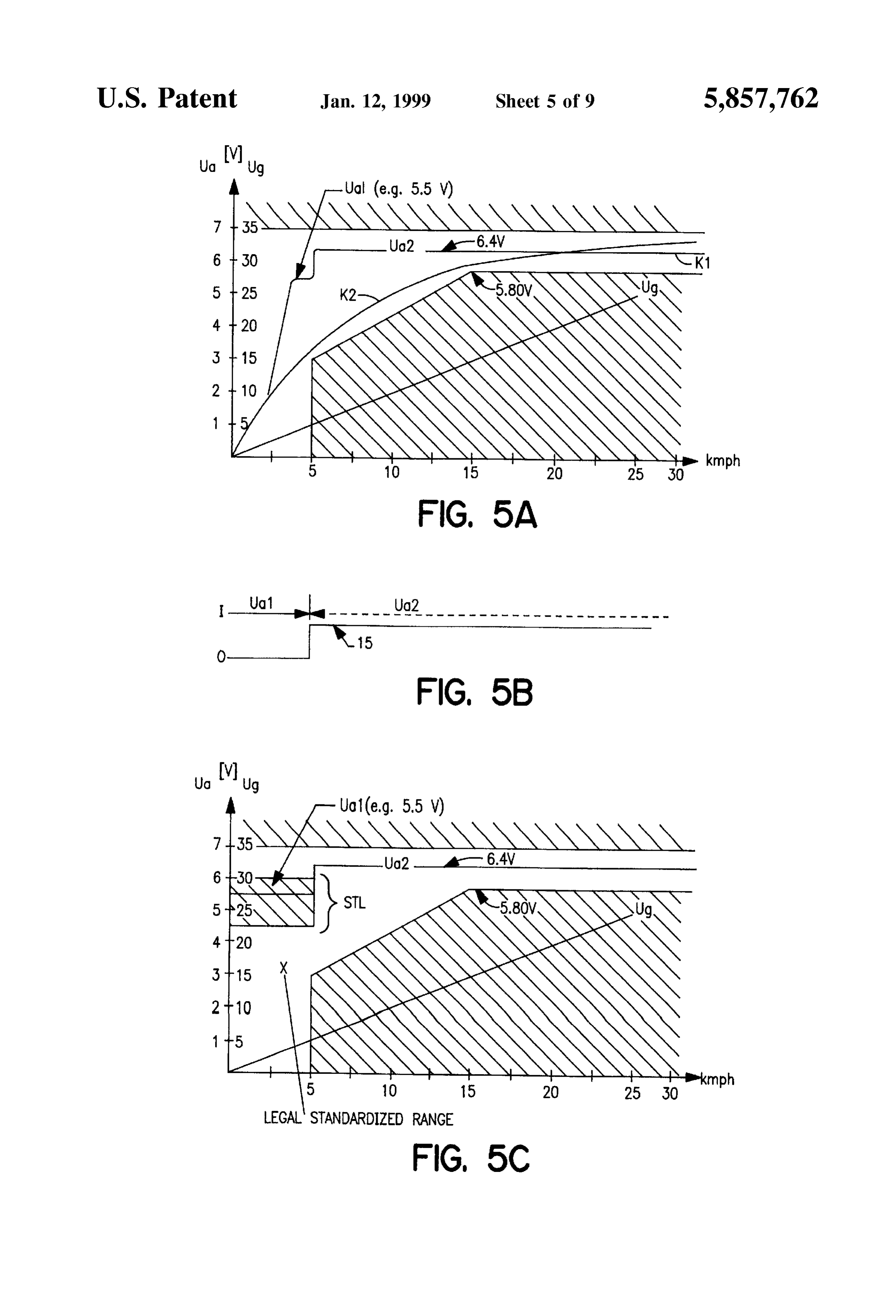
variation-in-time (FIG. 4a), the function of the first V, whereby the 80 V input voltage would correspond to threshold-value Switch 13 (FIG. 4b), the function of the a speed of approximately 80 kmph; delay circuit 17 (FIG. 4c), the function of the second energy apportioning in travel light and Standstill light is threshold-value Switch 15 (FIG. 4d) and the function of the thereby rendered possible in ratioS of 1-2:1, i.e. one output voltage U, i.e. U and U2 (FIG. 4e). to-two units travel light and one unit Standstill light, The delay circuit 17 is activated when the threshold irrespective of the travel Speed. Such apportioning voltage V falls short of approximately 0.8 V. In other words, ratioS are currently still rather limited by the charging the bicycle comes to a stop. The delay circuit 17 now capacity of rechargeable accumulator batteries. The Supplies by means of gate circuit T and Switch S1 the ratio can be Substantially reversed in the case of an Voltage of the battery 4 during a period of four minutes to the improved charging capacity and could be, for instance, circuit node 18 and thus to the Voltage-converting and a ratio of 1:2. However, Such batteries are still not energy-limiting device 10. The latter now produces the available or have other drawbacks; output Voltage for Standstill lighting. At the end of the time the inventive bicycle lighting System meets by far all legal interval of four minutes, the Switch S is opened and the requirements, Standards and Specifications relating to entire system is thereby switched off. In case the first 15 the dynamo/travel power curve, because constant and threshold-value Switch 13 exceeds the control signal V, adequate energy for lighting as well as battery charging when during the delay interval the voltage V is equal to 0.8 is non-intermittently available; V, the delay circuit 17 is set back to zero and there com by virtue of the effected division of the output voltage of mences the normal traveling program as described herein the Voltage-converting and energy-limiting device 10 before under the title “First threshold-value Switch 13”. of the electronic circuitry 5 to provide, on the one hand, In short, this means that when the bicycle comes to a Stop, an output voltage of 4.5 V up to 6 V below a speed of the Standstill or parking light will burn at least four minutes around 5 kmph and, on the other hand, a “travel long. Upon Starting anew, the lighting System changes over voltage” of 6.4 V, the Standard exacting 3 W for without interruption to the traveling program. Standstill and travel at any Speed is perfectly fulfilled; The battery monitoring circuit 19 depicted in FIG. 3 25 the battery charging balance is very reliably ensured; monitors the charge condition of the accumulator battery 4 by virtue of the comparatively superior efficiency of the and the operational capability of the latter. In case the battery entire inventive bicycle lighting System there is is discharged or defective, the battery monitoring circuit 19 achieved a Substantially lower riding resistance. In will prevent the connection of the accumulator battery 4 to other words, the cycling or pedaling energy required on the circuit node 18, So that the System is run and operated the part of the bicycle rider to actuate and drive the according to FIG. 5a directly by the dynamo generator 1 dynamo System is Substantially reduced in Spite of (voltage U.), in such case without bicycle-standstill light, increased dynamo power;
and by the Voltage-converting and energy-limiting device the application of the air-core coil 23 in the generator 1 10. It is thereby ensured that such accumulator batteries are 35 eliminates magnetic ripple formation; protected against total discharge. the dynamo generator 1 has extremely low inductive In FIGS.5a, 5b and 5c there is illustrated the course of the losses requires no sliding contacts and is, therefore, output voltage U achieved by the bicycle lighting System better and more reliable; and finally constructed in accordance with the invention. The course or progression of Such output voltage U is depicted in the form 40 the rotary motion of the entire magnetic circuit, i.e. the of a curve K extending between two areas defined by legal inner circuit 21 and the outer circuit 22, eliminates the Standards and shown in a hatched representation. The course magnetic losses of the dynamo generator 1. FIG.
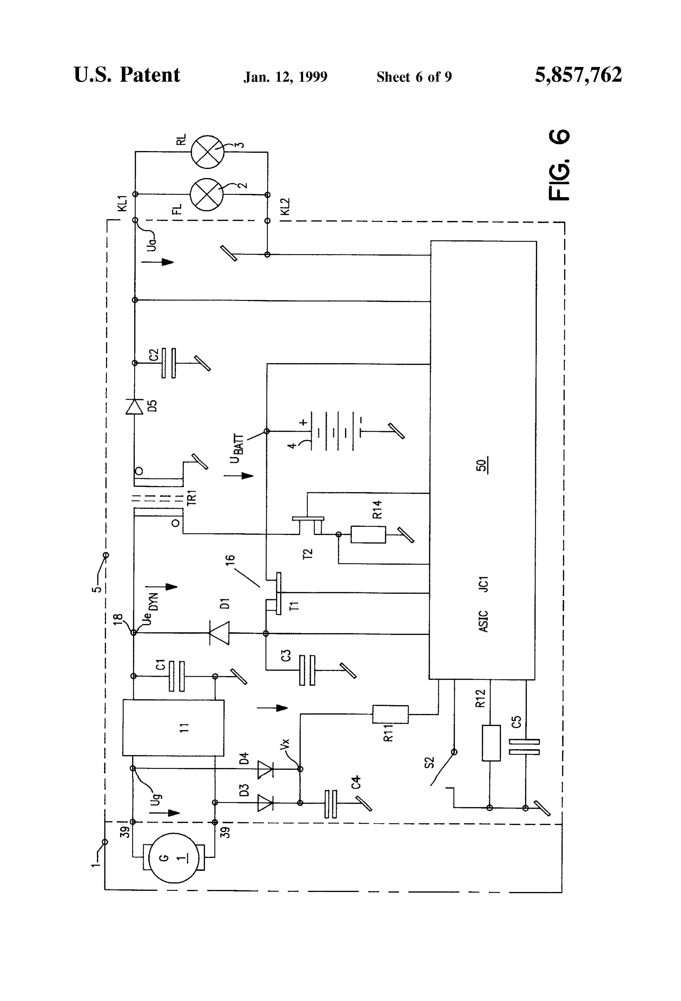
of the output voltage is designated by the reference charac the electronic6 shows an exemplary preferred accomplishment of ters U and U as will be recognized in FIG. 5b. On the State, integratedcircuitry 5 by means of a customized, Solid Switching circuit 50, at pins of which there other hand, in FIG. 5a there is depicted a curve K showing 45 are connected external circuit or control elements of the the course of the output Voltage of a conventional bicycle converter circuit.
lighting System. The bicycle Standstill-light area is conve Since all electronic functions are complex and costly and niently designated by reference character STL in FIG. 5c and Since the construction, which includes integrated Standard extends over a speed range from Zero to approximately 5 Switching circuits, would require a large number of compo kmph. 50 nents and component parts as well as a great deal of Space, The aforedescribed bicycle lighting System and the dynamo System in accordance with the invention thus have there digital are Sensibly and efficiently realized all functions, and analog functions, together in a One-Chip-ASIC in particular the following advantages: suitably also designated by reference character 50. Abicycle the dynamo generator 1 disposes of a comparatively very lighting System being a mass-produced or bulk article, it is high efficiency which provides a power output of more 55 evident that mass production of Such customized, Solid-State than 4.5 W at travel speeds of approximately 5 to 7 and integrated Switching circuit 50 is also economically kmph; Worth-while. The components that cannot be integrated or at a travel Speed above around 5 kmph, the dynamo cannot be Sensibly integrated, Such as the rectifier 11, the generator power is converted to 6.4 V and kept Stabi capacitors C to C, a transformer, a power output transistor lized by means of the converter of the electronic 60 and further component parts, are connected to the pins of the circuitry having a Voltage Set-up and Voltage Set-down customized, Solid-state and integrated Switching circuit 50 in mode of operation; the circuit arrangement illustrated in FIG. 6. this energy is directly available, on the one hand, for By virtue of the provision of a customized, Solid-state, rapidly charging the rechargeable accumulator battery integrated Switching circuit 50 for the electronic functions of and, on the other hand, for producing light; 65 the electronic circuitry 5, there is rendered possible a very the electronic circuitry 5 operates already from 2 V with compact and comparatively Small electronic circuitry which, an input Voltage Starting from 1.5V and going up to 80 together with the accumulator battery 4, can be accommo
Page 17
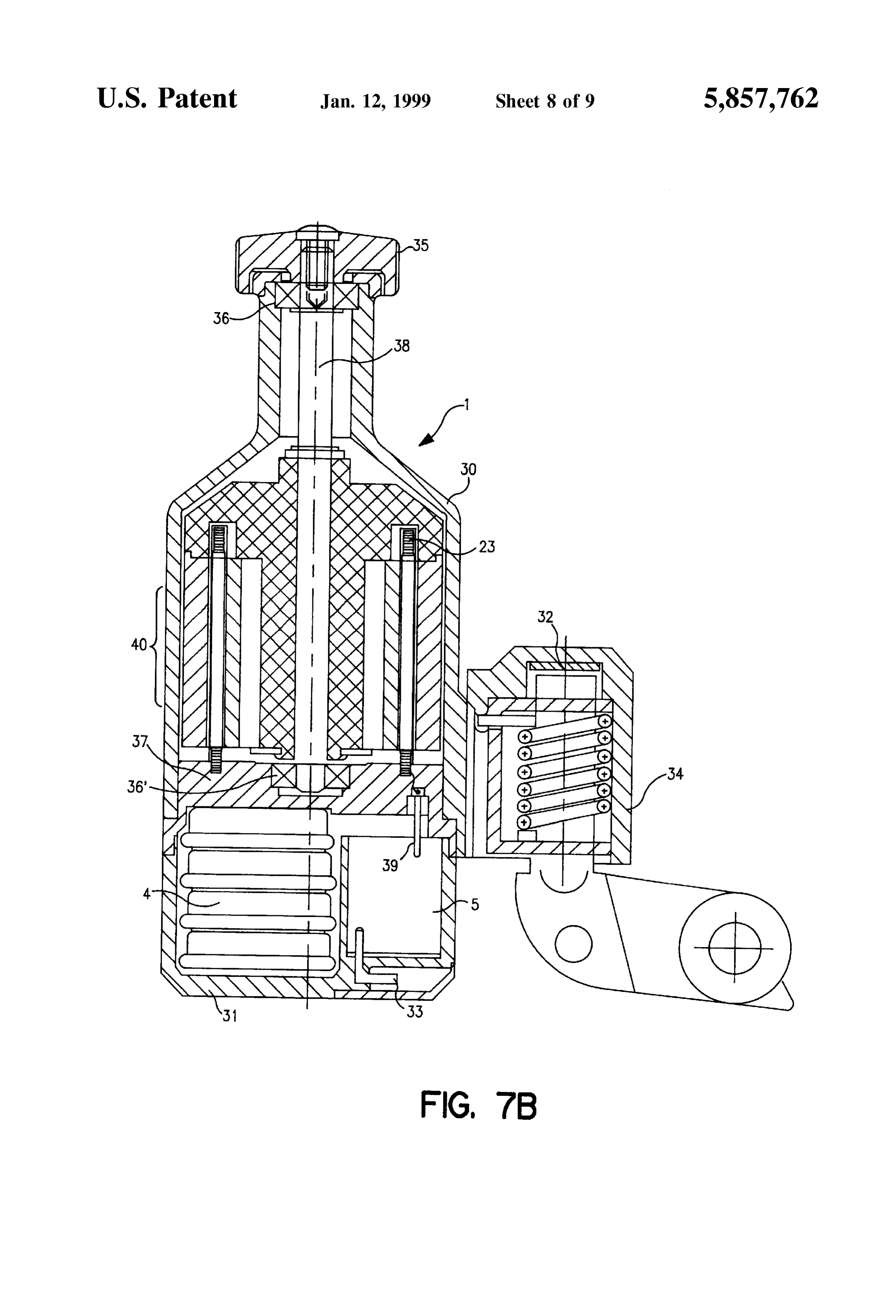
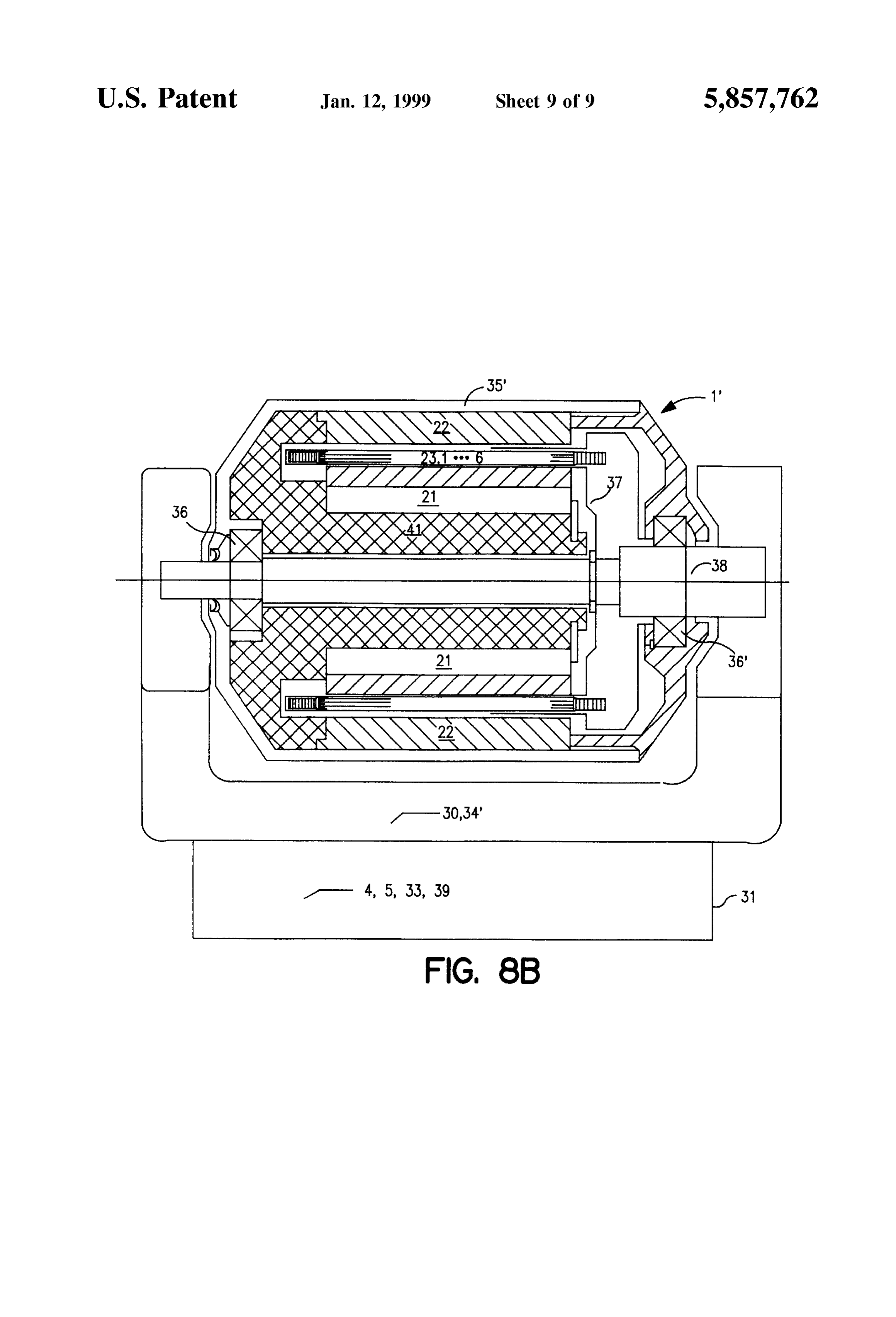
dated in an adequately Small housing which is either inte The Swivel arm 34' partially represents the upper housing grated with the dynamo generator housing or Separately portion 30 which encompasses the rotatable circuits 21, 22 mountable thereon. and the stationary coil sections 23.1 through 23.6. The lower In FIG. 7a there is schematically illustrated a standard or housing portion 31 is fixedly connected to the upper housing conventional bicycle provided with the dynamo generator 1 portion 30 and encompasses the battery 4 and the electronic Structured as a Side dynamo and with a lighting System circuitry 5. The stationary coil sections 23.1 through 23.6 are including a Standard front lamp 2 and a Standard rear lamp integrally formed with the housing base 37. 3. To facilitate the illustration, cables provided to connect A driving friction wheel 35' for frontally engaging the tire the dynamo generator 1 to Said Standard lamps 2 and 3 are of the rear bicycle wheel is fixedly mounted on the coaxially not particularly illustrated. In FIGS. 3 and 6, these lamps 2 rotatable dynamo shaft 38 which is rotatably mounted in the and 3, Schematically depicted and conveniently also desig pivot bearings 36 and 36". The driving friction wheel 35' nated by reference characters FL and RL, are fed by the thereby encases the outer circuit 22 and the inner circuit 21. electronic circuitry 5 in a Standard Specified parallel circuit. The dynamo shaft 38 is fixedly coupled to the non-ferrous FIG. 7b shows a longitudinal sectional view of an exem Support core 41 of the inner magnetic circuit 21. plary embodiment of the dynamo generator 1 constructed in 15 As shown in FIG. 6, it is evidently possible to provide an accordance with the present invention as a Side dynamo alternative exemplary embodiment of the dynamo System in including the accumulator battery 4 and the electronic that the electronic circuitry 5, the external components or circuitry 5. The dynamo system is mounted in known component parts thereof and the battery 4 are kept apart manner on a Swivel arm 34 and comprises an upper housing from the dynamo generator 1 and arranged quite Separately portion 30, which encompasses the rotatable inner and outer on the bicycle.
circuits 21 and 22 as well as the Stationary coil Sections 23.1 While there are shown and described present preferred through 23.6, and a lower housing portion 31 which encom embodiments of the invention, it is to be understood that the passes the integrated accumulator battery 4 and the inte invention in not limited thereto, but may be otherwise grated electronic circuitry 5, Such lower housing portion 31 variously embodied and practiced within the Scope of the being fixedly connected to the upper housing portion 30. The following claims. ACCORDINGLY, coil sections 23.1 through 23.6 are integrally formed with a 25 I claim:
housing base or bottom 37, and the electronic circuitry 5 is 1. A bicycle lighting System for pedal-driven vehicles, connected by means of guide pins 39 with the coil sections especially a bicycle, comprising:
23.1 through 23.6. Connections or leads 33 to the front lamp a dynamo System to produce electric power; 2 and the rear lamp 3 are located in the lower part of the at least one electric front lamp and at least one electric lower housing portion 31. rear lamp;
A Sensor 32, designated by reference character S. in Said at least one electric front lamp and Said at least one FIGS. 3 and 6, is advantageously accommodated in the electric rear lamp being conventionally mounted on the housing of the Swivel arm 34. Such sensor 32 detects that the bicycle, the latter having wheels each comprising a rim complete dynamo System is not ready for operation in the and a tire;
idle position thereof and Supplies a signal to the electronic 35 Said dynamo System being fixedly mounted on the bicycle circuitry 5, thereby immediately interrupting the existing or and having rotatably mounted Shaft means fitted with lit Standstill or parking lights. In other words, the Sensor 32 friction means,
Serves to deemergize the entire bicycle lighting System when Said friction means engaging the rim and/or the tire of at the dynamo on the Swivel arm 34 is tilted away from the side least one of Said wheels and thereby being rotatably of a tire or rim of the bicycle. Adriving friction wheel 35 for 40 driven when the bicycle is in motion; engaging Such bicycle tire or rim is fixedly fitted with a Said dynamo System comprising a dynamo generator dynamo arbor or shaft 38 which, in turn, is connected to the Serving to generate an electric power output, a support core 41 of the inner circuit 21. This dynamo shaft 38 rechargeable accumulator battery for Storing electric is freely rotatably mounted in an upper pivot bearing 36 and power, and an electronic circuit comprising a converter a lower pivot bearing 36". 45 for controlling input voltage from Said electric power
Although the dynamo System as shown in the longitudinal output;
sectional view in FIG. 7 is constructed as a side or laterally Said at least one electric front lamp and Said at least one mounted dynamo System, it will be readily clear to those electric rear lamp being Supplied with Said electric skilled in the art that the aforementioned characteristics of the dynamo System according to the present invention are 50 power either from Said dynamo generator or from Said also applicable for roller-dynamo and hub-dynamo Systems. rechargeable accumulator battery; In FIG. 8a there is schematically illustrated a standard or the bicycle in motion having a minimum travel Speed conventional bicycle provided with the dynamo generator between approximately 5 to 7 kmph; Structured as a roller dynamo. The lighting System includes Said dynamo generator being structured Such that Starting the standard front lamp 2 and the standard rear lamp 3 which 55 from Said minimum travel Speed Said electric power are fed by the electronic circuitry 5 in a Standard Specified output is adequate for rapid charging of Said recharge parallel circuit as depicted in FIGS. 3 and 6. able accumulator battery and for Simultaneously ener FIG. 8b shows a longitudinal sectional view of a second gizing Said at least one electric front lamp and Said at exemplary embodiment of the dynamo generator conve least one electric rear lamp to maintain a predetermined niently designated by reference character 1" and Structured as 60 illumination level;
a roller dynamo including the battery 4 and the electronic Said dynamo generator accordingly comprising an inner circuitry 5. The dynamo System is mounted on a bow-shaped circuit and an outer circuit; Swivel arm 34' arranged in front of the rear wheel of the Said dynamo generator further comprising a Stationary bicycle such that the rotational axis of the dynamo shaft 38 air-core coil comprising coil Sections, is Substantially perpendicular to the plane of the bicycle 65 Said inner circuit and Said outer circuit being mounted on frame or, in other words, parallel to the axle of Said rear Said Shaft means for Synchronous rotation about Said wheel. Stationary air-core coil;
Page 18
Said inner circuit and Said outer circuit each comprising in Said n inner pole Shoes each comprise a peripheral Sur poles in identical pole pitch; face; and
Said converter of Said electronic circuitry being Structured Said Sum of Said two lateral magnet faces being Substan Such that said input Voltage fed from Said dynamo tially larger than Said peripheral Surface. generator is converted into a determinate stabilized 5 7. The bicycle lighting System as defined in claim 1, output voltage; wherein:
Said converter accordingly comprising a Voltage Set-up Said Stationary air-core coil of Said dynamo generator and Voltage Set-down mode of operation Such that, for comprises an inductance lesser than 150 uH. Said determinate Stabilized output voltage, Said input 8. The bicycle lighting system as defined in claim 7, Voltage may be lesser than, equal to, or greater than Said wherein:
determinate Stabilized output Voltage, and Said Stationary air-core coil comprises a coil resistance Said input voltage for said converter being additionally lesser than 1.5 ohms, and provided by Said rechargeable accumulator battery as Said dynamo generator possesses an internal resistance long as Said minimum travel Speed is not reached. 5 likewise lesser than 1.5 ohms.
2. The bicycle lighting System as defined in claim 1, 1. 9. The bicycle lighting system as defined in claim 1, wherein: wherein:
Said n poles of Said inner circuit constitute n inner pole Said Stationary air-core coil comprising coil Sections shoes and Said n poles of Said outer circuit constitute in forms together with Said n inner pole Shoes respective outer pole shoes, and 2O pole fields;
Said in outer pole Shoes being Substantially oppositely Said coil Sections being divided per pole field into two located with respect to Said n inner pole Shoes. identical coil Sections, and 3. The bicycle lighting System as defined in claim 2, Said two identical coil Sections per pole field being further including: pole-correctly connected in Series. magnetic poles provided in pairs between said n inner 25 10. The bicycle lighting system as defined in claim 1, pole Shoes, wherein:
Said n inner pole shoes each comprising two lateral Sides, Said number of poles in represents at least four poles, and and
Said at least four poles being preferably six poles.
Said pairs of magnetic poles being arranged in Such a 11. The bicycle lighting System as defined in claim 1, manner that, in each case, Said magnetic poles rest in wherein:
homopolar configuration against Said two lateral Sides the bicycle in motion has a slow-moving Speed range of each of Said n inner pole Shoes. which is even below said minimum travel speed 4. The bicycle lighting System as defined in claim 3, between approximately 5 to 7 kmph; wherein: 35 Said Slow-moving Speed range lying between approxi Said in outer pole shoes extend nose-shapedly toward Said mately 3.5 and 5 kmph;
n inner pole shoes and thereby define, in each case, an Said electric power output at Said slow-moving Speed air gap between Said n inner pole Shoes and Said in outer range between approximately 3.5 and 5 kmph and pole Shoes, and under a load of 3 ohms amounts to at least 3 W; and Said air gaps each being a shortest possible path for a 40 Said electric power output at Said minimum travel Speed magnetic flux. between approximately 5 and 7 kmph amounts to at 5. The bicycle lighting system as defined in claim 3, least 4.5 W.
wherein:
12. The bicycle lighting System as defined in claim 1, the provision of Said magnetic poles in pairs between Said wherein:
n inner pole shoes entails providing n permanent mag 45 Said generated electric power output of Said dynamo netS, generator varies by approximately 0.8 V to 1.2 V per 1 Said in permanent magnets being positioned in Such a kmph variation in travel Speed of the bicycle. manner that, in each case, Said in permanent magnets 13. The bicycle lighting System as defined in claim 1, bear in homopolar configuration against Said two lateral 50 wherein:
Sides of each of Said n inner pole shoes, Said dynamo System comprising Said dynamo generator, Said n inner pole shoes each comprise a mid-portion Said rechargeable accumulator battery and Said elec Structured to have a slot extending in a direction tronic circuitry is constructionally realized as a Side Substantially radial with respect to Said Synchronous dynamo.
rotation of Said inner circuit together with Said outer 55 14. The bicycle lighting System as defined in claim 1, circuit; and wherein:
Said slots each defining an air gap and thereby reducing Said dynamo System comprising Said dynamo generator, mutual interference of Said in permanent magnets lat Said rechargeable accumulator battery and Said elec erally bearing, in each case, in homopolar configuration tronic circuitry is constructionally realized as a friction against Said n inner pole Shoes. 60 roller dynamo.
6. The bicycle lighting system as defined in claim 5, 15. The bicycle lighting system as defined in claim 1, wherein: wherein:
Said in permanent magnets each comprise two lateral Said converter of Said electronic circuitry comprises a magnet faces, Voltage-converting and energy-limiting device for con lateral Surface area of Said in permanent magnets laterally 65 Verting Said input voltage into Said determinate Stabi bearing against Said n inner pole shoes is, in each case, lized output voltage and for limiting converted energy a Sum of Said two lateral magnet faces, to a determinate maximum energy value;
Page 19
Said electronic circuitry further comprises a threshold limiting device by means of Said electronic Switchgear value device and an electronic Switchgear; when said rectified and Smoothed dynamo output volt Said electronic circuitry providing a rectified and age exceeds a first threshold Voltage detected by Said Smoothed dynamo output voltage having a determinate first threshold-value Switch, said first threshold voltage minimum voltage; 5 corresponding with Said determinate minimum Voltage; Said rechargeable accumulator battery providing a battery and
Voltage output, and Said Second threshold-value Switch Supplying to Said Said threshold-value device being Structured to detect Said Voltage-converting and energy-limiting device a Signal rectified and Smoothed dynamo output voltage to Switch over Said output Voltage of Said Voltage whereby, in case Said threshold-value device detects 1O converting and energy-limiting device from Said first constant output voltage range to Said Second constant that Said determinate minimum Voltage is exceeded, output voltage range and Vice versa, whenever Said Said battery Voltage output is fed, in addition to Said Second threshold-value Switch detects that said Second rectified dynamo output Voltage, by means of Said threshold Voltage is exceeded or no longer exceeded, electronic Switchgear to Said Voltage-converting and energy-limiting device. 15 20"E lighti t defined in claim 19 16. The bicycle lighting system as defined in claim 15 wherein. e DIcycle IIgnung System as dellned In claim ly, wherein: - - -
Said determinate Stabilized output Voltage lies, during Said electronic circuitry comprises a delay circuit con battery operation, within a first constant output voltage 20 nected to an output of said first threshold-value switch range and, during dynamo operation, within a Second and to Said electronic Switchgear; constant output Voltage range; a time delay of Said delay circuit defining a predetermined Said Second constant output Voltage range lying above period of time;
Said first constant output Voltage range; Said delay circuit being activated when Said rectified and Said electronic circuitry comprises a battery charging 25 Smoothed dynamo output Voltage falls Short of Said first threshold Voltage, and thereby opening Said electronic device; Switchgear to Supply Said battery Voltage output to Said Said battery charging device having a determinate charg Voltage-converting and energy-limiting device; ing output voltage above which Said battery charging Said Voltage-converting and energy-limiting device device is activated; and 3O thereby producing output voltage which, in case of Zero Said determinate charging output Voltage lying between travel Speed, provides Standstill lighting during Said Said first constant output Voltage range and Said Second predetermined period of time; constant output Voltage range. said electronic Switchgear Switching off Said battery volt 17. The bicycle lighting system as defined in claim 16, age output from the input of Said Voltage-converting wherein: 35 and energy-limiting device at the end of Said predeter Said first constant output voltage range of Said electronic mined period of time;
circuitry lies in a range from 4 V to 6 V, but preferably Said battery charging device of Said electronic circuitry is from 4.5 V to 5 V; and provided with an output Side coupled to Said Voltage Said determinate charging output voltage is preferably 6.1 converting and energy-limiting device; and V. - 0 said battery charging device remaining, also in the case of The bicycle lighting System as defined in claim 16, battery operation, activated for charging Said recharge WCC able accumulator battery.
Said Voltage-converting and energy-limiting device limits 21. The bicycle lighting system as defined in claim 20, Said electric power output of Said electronic circuitry wherein:
invariably between 4W and 6 W, preferably invariably 45 Said dynamo generator is provided with Sensor means for between 4.5 W and 5 W. detecting that Said dynamo generator in an idle position 19. The bicycle lighting system as defined in claim 16, thereof is not ready for operation; wherein: Said Sensor means thereby transmitting to Said electronic Said electronic circuitry further comprises: 50 circuitry a signal to put out Said Standstill lighting if a rectifier circuit for producing Said rectified and existing, and
Smoothed dynamo output Voltage which is Supplied to Said idle position being brought about by tilting away Said Said Voltage-converting and energy-limiting device; dynamo generator from engaging Said rim and/or Said a first Voltage divider network for converting a first tire of at least one of Said bicycle wheels. rectified and Smoothed output voltage of said dynamo is wherein: 22. The bicycle lighting system as defined in claim 19, generator, Said output voltage being proportional to the travel Speed, into a first component Voltage, and for Said electronic circuitry comprises a customized, Solid Supplying this first component Voltage to a first State and integrated Switching circuit. threshold-value Switch of said threshold-value device; 23. The bicycle lighting System as defined in claim 1, a second voltage divider network for converting said 60 further including:
rectified and Smoothed output Voltage of Said dynamo a housing located apart from Said dynamo generator, and generator, Said output voltage being proportional to the Said electronic circuitry together with Said rechargeable travel Speed, into a Second component Voltage, and for accumulator battery being arranged in Said housing. Supplying this Second component Voltage to a Second 24. The bicycle lighting System as defined in claim 1, threshold-value Switch of said threshold-value device; 65 further including:
said first threshold-value Switch feeding said battery volt- a housing provided for Said electronic circuitry together age output to Said Voltage-converting and energy- with Said rechargeable accumulator battery;
Page 20
Said dynamo generator being accommodated in a dynamo 27. The generator as defined in claim 26, wherein: housing, and Said n inner pole shoes each comprise a mid-portion Said housing being mounted on Said dynamo housing. Structured to have a slot extending in a direction which 25. The bicycle lighting system as defined in claim 1, is Substantially radial with respect to Said Synchronous further including: rotation of Said inner circuit together with Said outer a two-parted housing to accommodate Said electronic circuit, and circuitry and Said rechargeable accumulator battery Said slots each defining an air gap in order to reduce together with Said dynamo generator. mutual interference of Said in magnets laterally bearing 26. A generator, comprising: in each case in homopolar configuration against Said in inner pole shoes.
an inner circuit and an outer circuit; 28. The generator as defined in claim 27, wherein: a Stationary air-core coil comprising coil Sections, Said in magnets each comprise two lateral magnet faces, Said inner circuit and Said outer circuit being rotatably Surface area of Said in magnets laterally bearing against mounted for Synchronous rotation about Said Stationary 15 Said n inner pole shoes is, in each case, a Sum of Said air-core coil; two lateral magnet faces,
Said inner circuit comprising n inner pole shoes in iden Said n inner pole Shoes each comprise a peripheral Sur tical pole pitch; face; and
Said outer circuit comprising in Outer pole shoes in iden Said Sum of Said two lateral magnet faces being Substan tical pole pitch; tially larger than Said peripheral Surface. Said in outer pole Shoes being Substantially oppositely 29. The generator as defined in claim 26, wherein: located with respect to Said n inner pole Shoes, Said Stationary air-core coil comprising coil Sections con n magnets respectively provided between Said n inner Stitutes with Said n inner pole shoes respective pole pole Shoes in Said identical pole pitch; 25 fields;
Said n inner pole shoes each comprising two lateral Sides, Said coil Sections being divided per pole field into two identical coil Sections, and
Said in magnets being positioned in Such a manner that, in Said two identical coil Sections per pole field being each case, Said in magnets rest in homopolar configu pole-correctly connected in Series. ration against Said two lateral Sides of each of Said in 30. The generator as defined in claim 26, wherein: inner pole shoes, Said number n defining the number of inner pole shoes, Said in outer pole shoes being Structured to extend nose Outer pole shoes and magnets represents an even num shapedly toward said n inner pole shoes and thereby ber; and define, in each case, an air gap between said in outer Said in magnets are preferably Structured as n permanent pole Shoes and Said n inner pole shoes, and 35 magnets.
Said air gaps being in each case a shortest possible path for a magnetic flux.
Page 21
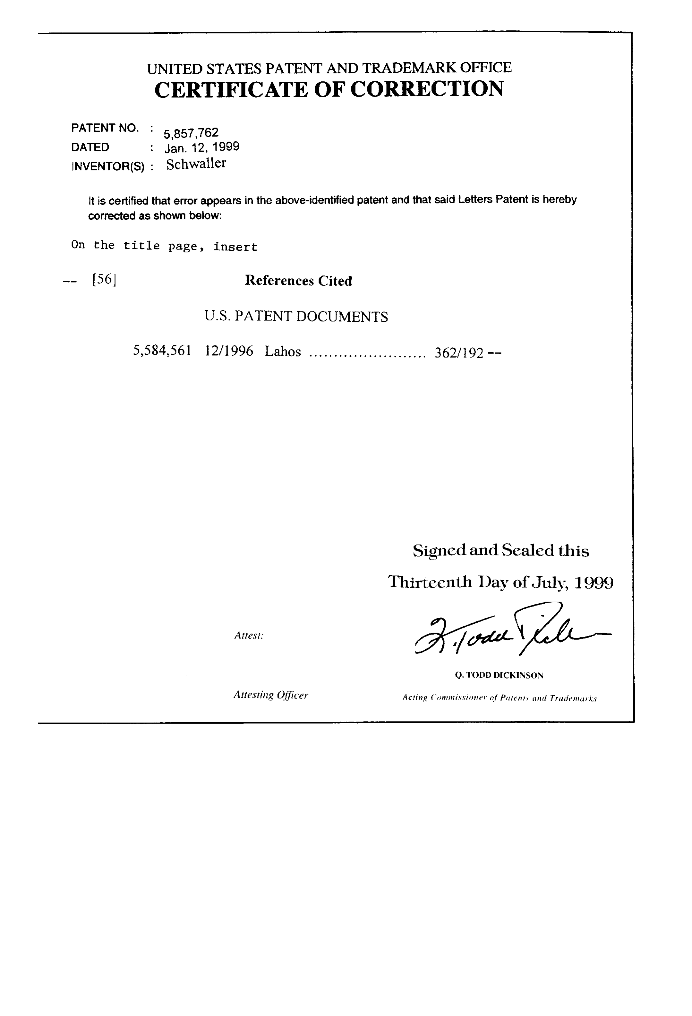
UNITED STATES PATENT AND TRADEMARK OFFICE
CERTIFICATE OF CORRECTION
PATENT NO. :: Jan.
DATED
INVENTOR(S) : Schwaller it is certified that error appears in the above-identified patent and that said Letters Patent is hereby corrected as shown below:
On the title page, insert
Signed and Sealed this
Thirteenth Day of July, 1999
Q. TODD DICKNSON
Attesting Officer Acting Commissioner of Patents and Tradenarks
Provenance
- Collection
- Cited prior art
- Original PDF
- patentimages.storage.googleapis.com →
- Filed
- 1995-01-11
- Pages
- 21
- Method
- pdftotext (the PDF's own text layer) + pdftoppm 300dpi page scans
- Source
- Google Patents bibliographic record
- Granted
- 1999-01-12
- Inventors
- Edwin Schwaller
- Transcribed from
- patentimages.storage.googleapis.com →