patent · US4694654
Exhaust energy recovery and generator for use with an engine
22 September 1987
Page 1 — bibliographic record
United States Patent (19) 11 Patent Number: 4,694,654 Kawamura 45 Date of Patent: Sep. 22, 1987 54 EXHAUST ENERGY RECOVERY AND 2.941240 4/1981 Fed. Rep. of Germany ........ 60/597 GENERATOR FOR USE WITH AN ENGINE 2499326 8/1982 France .
75) Inventor: Hideo Kawamura, Samukawa, Japan 192652 11/1937 Switzerland . 73 Assignee: Isuzu Motors Limited, Tokyo, Japan 1437532 5/1976 United Kingdom........... 4.5/212. A
(21) Appl. No.: 666,058 2063368 6/1981 United Kingdom.
Primary Examiner-Douglas Hart 30 Foreign Application Priority Data Attorney, Agent, or Firm-Staas & Halsey Oct. 29, 1983 JP Japan ................................ 58-203238 57 ABSTRACT Oct. 31, 1983 JP Japan .. ... 58-204569
Mar. 7, 1984 JP Japan .................................. 59.51558 An engine is composed of an exhaust turbine rotatable by the exhaust energy of an exhaust gas discharged 51) Int. Cl. .............................................. FO2B37/00 from the engine, a generator coupled to the exhaust 52 U.S. C. ........................................ 60/605; 60/602; turbine, and a motor drivable by the generator. The 290/52; 310/102 R; 310/156; 310/168; 363/37; energy recovered from the exhaust gas by the exhaust 415/212 R turbine is fed back to an output shaft of the engine 58 Field of Search ................. 60/602, 605, 624, 597; through the generator and the motor. The engine may 310/156, 168, 68 R, 102 R, DIG. 3, 113; have a second exhaust turbine located downstream of 290/52; 415/212 R, 214; 363/37 the first-mentioned exhaust turbine in an exhaust pas 56) References Cited sage for driving an intake air compressor. The exhaust
turbine by a bypass passage. In a generator device used 3,007,302 11/1961 Vincent ............................. 60/605 R with the engine, the generator includes a rotor shaft 3,062,979 11/1962 Jarret et al. . coupled coaxially with a turbine wheel shaft of the 3,217,194 11/1965 Terry et al. . exhaust turbine. The turbine wheel, the wheel shaft, and 3,529,222 9/1970 Gaitten .................................. 363/37 3,849,682 11/1974 Binns ................................... 30/156 the rotor shaft are constructed of ceramics preferably as 3,968,390 7/1976 Yasuda ................................ 310/156 an integral structure. The rotor shaft is rotatably sup 4,253,031 2/1981 Frister ................................... 290/52 ported by oil floating bearings. On the rotor shaft, there 4,280,797 7/1981 Pfeil....... ., 41.5/212 R is mounted a magnet rotor of a rare earth metal kept in 4,391,098 7/1983 Kosuge. ... 60/60S R position by holder plates held against opposite axial 4,394,582 7/1983 Kreissl................................... 290/52 ends of the magnet rotor. A carbon wire is coiled 4,406,958 9/1983 Palmero .............................. 310/156 around the magnet rotor. Alternatively, a magnet hous 4,408,959 10/1983 Long ................................... 4.5/214 ing is mounted on the rotor shaft and comprises a plural 4,545,464 10/1985 Nomura ................................ 363/37 ity of housing members held axially together, and a
FOREIGN PATENT DOCUMENTS magnet of a rare earth metal is accommodated in reces 0057544 2/1981 European Pat. Off. . ses in each pair of housing members. -
197483 4/1907 Fed. Rep. of Germany . 8 Claims, 8 Drawing Figures
NVERTER
Page 2
Drawing sheet — no readable text.
Page 3
Drawing sheet — no readable text.
Page 4
Drawing sheet — no readable text.
Page 5
Drawing sheet — no readable text.
Page 6
Drawing sheet — no readable text.
Page 7
rotative power from the exhaust turbine is applied
EXHAUST ENERGY RECOVERY AND through a train of gears to the crankshaft of the engine. GENERATOR FOR USE WITH AN ENGINE With the above exhaust energy recovery process, however, the turbine cannot respond well to variations
BACKGROUND OF THE INVENTION 5 in the speed of flow of the exhaust gas. The speed re The present invention relates to an exhaust energy ducer required to reduce the high speed of rotation of recovery and generator device for use with an engine the exhaust turbine has not yet been practically avail able since it would be highly complex in construction (referred to hereinafter as a "generator device'). and reduce the efficiency of transmitting power. Internal combustion engines, such as gasoline engines and diesel engines, produce a power output by combust tors to behave
There heretofore been used induction genera ing fuel in cylinders to generate an energy with which generators having by driven exhaust turbines, the induction permanent magnet rotors to with the pistons are lowered. An exhaust gas produced by stand centrifugal forces applied thereto. However, limi the combustion of the fuel in the cylinder is discharged tations have been imposed on the speed of rotation of through an exhaust manifold into the atmosphere. The 15 the rotor due to the strength of the magnet and weak exhaust gas has a high temperature and a high pressure magnetic forces thereof when the rotor is to be rotated and still retains a considerable amount of energy. at high speeds. As a consequence, it has been difficult to There has recently been developed a thermally insu manufacture a high-power generator of this type. lative internal combustion engine with various parts Generators generate greater electric power as the constructed of ceramics, including an outer wall of an 20 rotor rotates at a higher speed. Therefore, the genera exhaust manifold, a cylinder liner, a heat-insulative tors as they are driven by exhaust turbines rotated at plate on a cylinder head, an exhaust valve, and a piston, high speeds by the exhaust energy are most effective for example. This type of internal combustion engine is means for efficiently utilizing the exhaust energy. not designed to radiate heat generated therein to cool For driving a synchronous generator with an exhaust the engine, but is rather designed to recover the energy 25 turbine and supplying regenerative energy to an inter of an exhaust gas which is of a higher temperature than nal combustion engine, it has been customary to pick up that of the exhaust gas emitted from conventional en an induced voltage from a rotor winding through a gines, thus increasing the operation efficiency of the brush or from a stator winding disposed around the engine. One conventional exhaust energy recovery de permanent magnet rotor. Such an arrangement causes vice includes a turbine disposed near an exhaust port no problem if incorporated in an ordinary generator and rotatable by an exhaust gas for producing excessive having a rotor speed of about 3,000 rpm. However, if a rotative power which is reduced in speed by a number rotor speed were 20,000 rpm or higher, then the genera of speed reducer gears and fed back to a crank shaft. tor would be damaged due to increased friction, or However, the prior exhaust energy recover device has frictional or sliding shocks.
been disadvantageous and ineffective in that it is com 35 The generator with the permanent magnet cannot plex in overall construction, making the internal com generate a sufficiently large amount of electric power bustion engine costly, has a poor operation efficiency, and hence cannot have a large power generation capac ity since the permanent magnet of metal produces only and cannot be used under a partial load. small magnetic forces.
There is known another exhaust energy recovery device for use with an ordinary engine having an engine SUMMARY OF THE INVENTION cooling device, rather than with the thermally insula It is an object of the present invention to provide an tive engine. The exhaust energy recovery device has a exhaust energy recovery and generator device for use turbine disposed near an exhaust port and rotatable by with an engine system with an capable of highly effi an exhaust gas, and an air compressor rotatable by the 45 ciently recovering the energy of an exhaust gas for turbine for feeding air under pressure into an intake increasing the operation efficiency of the engine and manifold to increase the engine operation efficiency making a supercharging operation effective, the genera when the engine rotates at a high speed and under a tor device being capable of high-speed rotation and high load. The turbine is required to operate at high producing a sufficiently large amount of electric power. speeds for supplying compressed air effective for high 50 Another object of the present invention is to provide engine rotational speeds. However, the turbine fails to a generator device of the foregoing type having a rotor Supply such effective compressed air when the exhaust shaft coupled coaxially with the turbine impeller shaft gas flows at a low speed, that is, the turbine cannot feed of an exhaust turbine for high-speed rotation. air into the engine when the engine rotates at a low Still another object of the present invention is to speed and under a high load. Another drawback is that 55 provide a generator device of the type described above, when the engine rotates at a high speed, the turbine which has a generator of sufficient mechanical strength tends to supply an excessive amount of air under pres to provide against high-speed rotation and includes a sure into the engine, and it is necessary to discharge a rotor for producing stroke magnetic forces, thus en portion of the exhaust gas through a bypass passage into abling the generator to produce a high power output the atmosphere. Such a bypass passage discharges the and operate highly efficiently.
entire exhaust energy into the atmosphere when the A still further object of the present invention is to engine rotates at a low speed. Accordingly, the exhaust provide a generator device of the type described above energy recovery device fails to utilize the exhaust en including a reluctance generator having a mechanism ergy effectively. strength large enough to withstand high-speed rotation. According to the process of recovering the exhaust 65 - According to the present invention, there is provided gas energy from an internal combustion engine in the an exhaust energy recovery and generator device for an form of a torque or power, as described above, the engine including an exhaust turbine disposed in an ex exhaust turbine is rotated by the exhaust gas energy, and haust passage of the engine and rotatable by the energy
Page 8
of an exhaust gas discharged from the engine, a genera DESCRIPTION OF THE PREFERRED tor having a rotor shaft connected to a turbine shaft of EMBODIMENTS the exhaust turbine, a motor drivable by the generator,
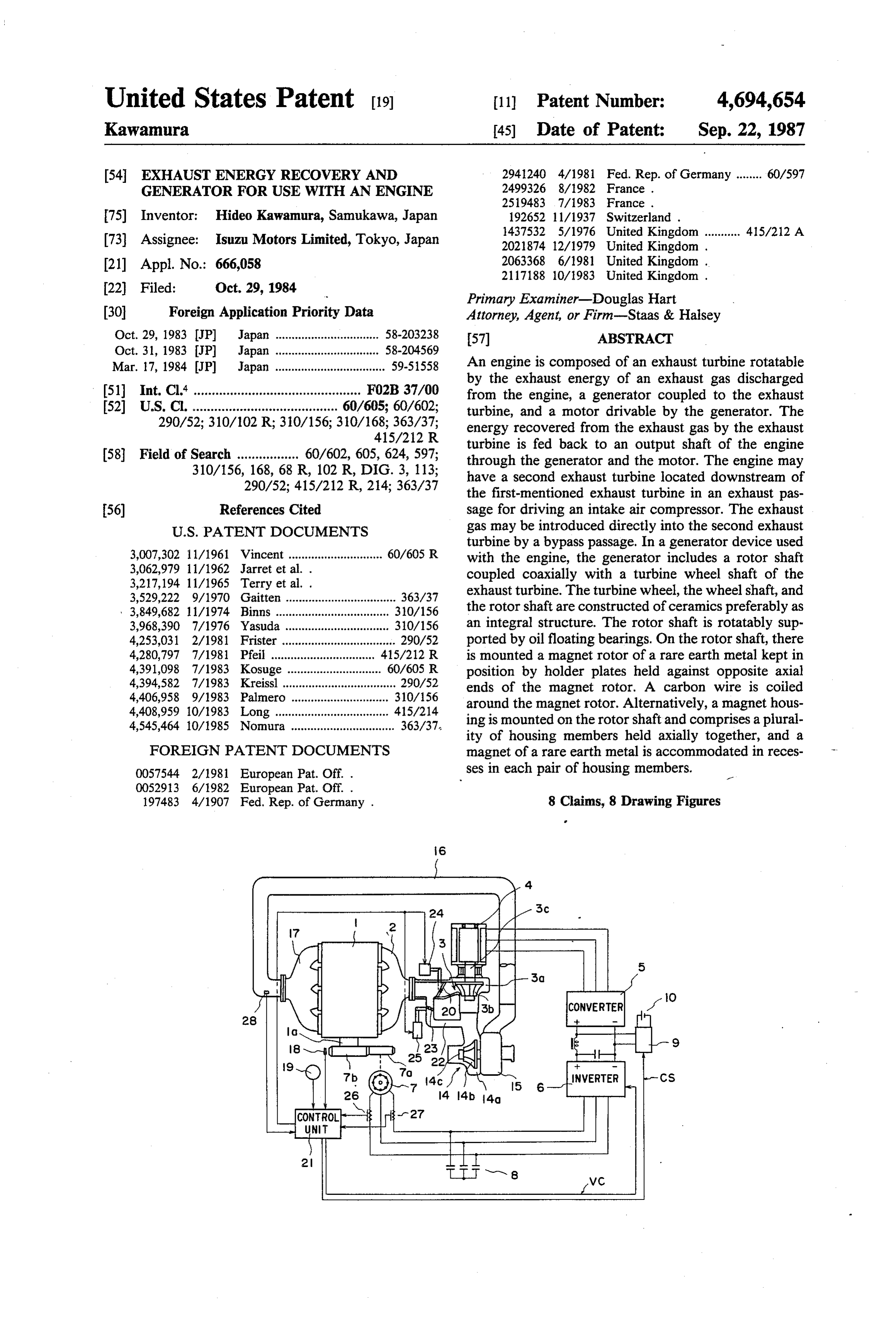
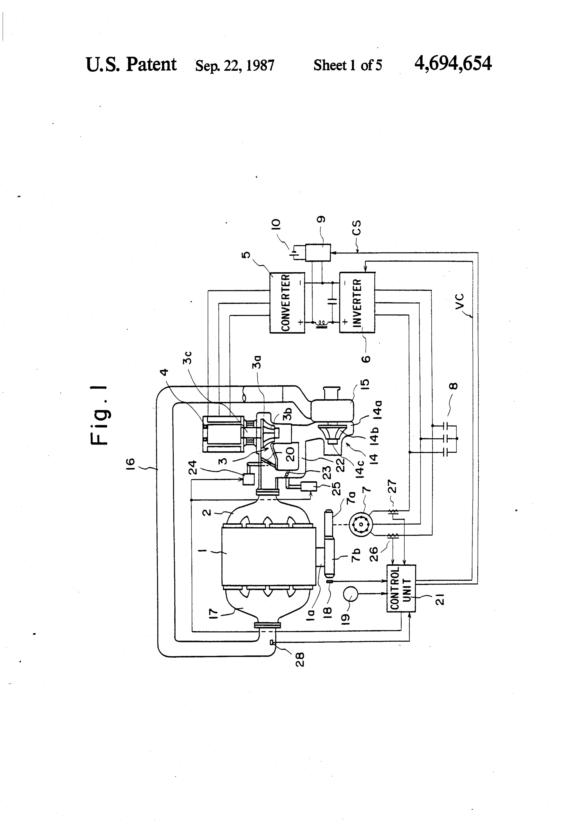
FIG. 1 illustrates a thermally insulative engine ac and means connecting a rotatable shaft of the motor to 5 cording to the present invention. The thermally insula an output shaft of the engine, whereby the energy of the tive engine exhaust gas recovered by the exhaust turbine can be fed is mounted typically on an automobile. The thermally insulative engine, indicated by the back to the output shaft of the engine through the gen reference erator and the motor, the exhaust turbine including a numeral 1, have various parts made of ceram turbine wheel having a wheel shaft coupled coaxially ics, the parts including a cylinder liner, a heat-insulative with the rotor shaft of the generator. plate for a cylinder head, an exhaust valve, and a piston, The turbine wheel of the exhaust turbine is con for example. An exhaust manifold 2 has a heat-insulative structed of ceramics. The rotor shaft of the generator first construction with its outer wall made of ceramics. A also is constructed of ceramics. Preferably, the turbine haustexhaust turbine 3 is coupled to an end of the ex manifold 2. The first exhaust turbine 3 is of the wheel, the wheel shaft, and the rotor shaft are con 15 high-speed type which produces an effective output structed integrally of ceramics. The rotor shaft of the when rotating at a high speed since a high-temperature, generator is rotatably supported by oil floating bear high-speed exhaust gas from the exhaust manifold 2 ings. passes through the first exhaust turbine 3. The first The generator device further includes a magnet rotor exhaust turbine 3 includes a turbine swirl chamber 3a in of a rare earth metal fitted over the rotor shaft of the 20 which a turbine wheel 3b is rotatably disposed. generator, holder members mounted on the rotor shaft A high-voltage AC generator 4 has a rotatable shaft and held against opposite ends of the magnet rotor, and coupled directly with a turbine shaft 3c of the exhaust a carbon wire coiled around a circumferential surface of turbine 3. The AC generator 4 comprises a bipolar AC the magnet rotor. generator having a rotor constructed of a permanent Alternatively, the generator device further includes a 25 magnet and a stator on which an armature winding is magnet housing fitted over the rotor shaft of the genera mounted. Since the AC generator 4 is driven by the tor and composed of housing members held axially exhaust turbine 3 to rotate at up to about 100,000 rpm, together and each having a central hole through which the rotor is of a slender configuration elongated in the the rotor shaft extends and a recess defined in at least axial direction of the rotatable shaft to reduce centrifu one surface thereof, and a magnet of a rare earth metal 30 gal forces imposed on the rotor as it rotates at a high disposed in the recesses in each pair of housing men speed, thus preventing the rotor from being damaged or bers. broken. The AC generator 4 as it rotates at a high speed The generator device further includes a body of sili generates an alternating voltage of about 200v, which is consteel fitted over the rotor shaft of the generator, and high for automotive use, at a frequency of about 3.5 a stator coil for passing an armature current which is 90' 35 KHz. A converter 5 composed of a thyristor bridge advanced in phase through a winding which generates a serves to convert an alternating current generated by no-load induced electromotive force, whereby the gen the AC generator 4 into a direct current (including erator serves as a reluctance generator. ripples). The thyristors of the converter 5 are high-fre The above and other objects, features and advantages 40 quency thyristors designed to sufficiently operate at the of the present invention will become more apparent frequency of about 3.5 KHz. The direct current pro from the following description when taken in conjunc duced by the converter 5 is converted by an inverter 6 tion with the accompanying drawings in which pre into an alternating current. The inverter 6 generates an alternating current having a frequency commanded by a ferred embodiments of the present invention are shown command signal VC supplied from a control unit 21, by way of illustrative example. 45 described later, the frequency being in the range of from BRIEF DESCRIPTION OF THE DRAWINGS a few tens Hz to a few hundreds Hz dependent on the FIG. 1 is a schematic representation of a thermally has rotational speed of the engine 1. An induction motor 7 insulative engine according to the present invention; a rotatable shaft coupled to an output shaft 1a of the engine 1 through two gears 7a, 7b. Designated in FIG.
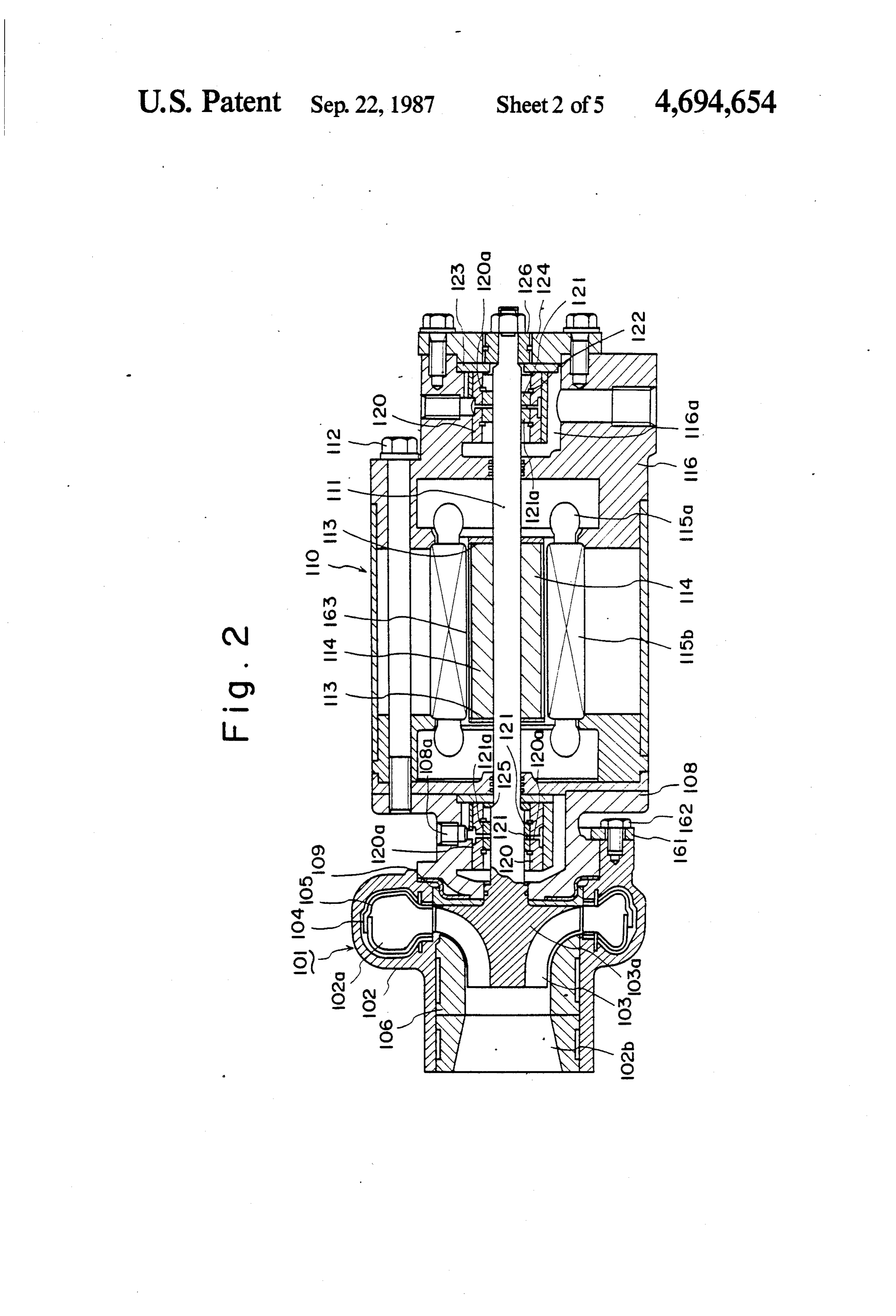
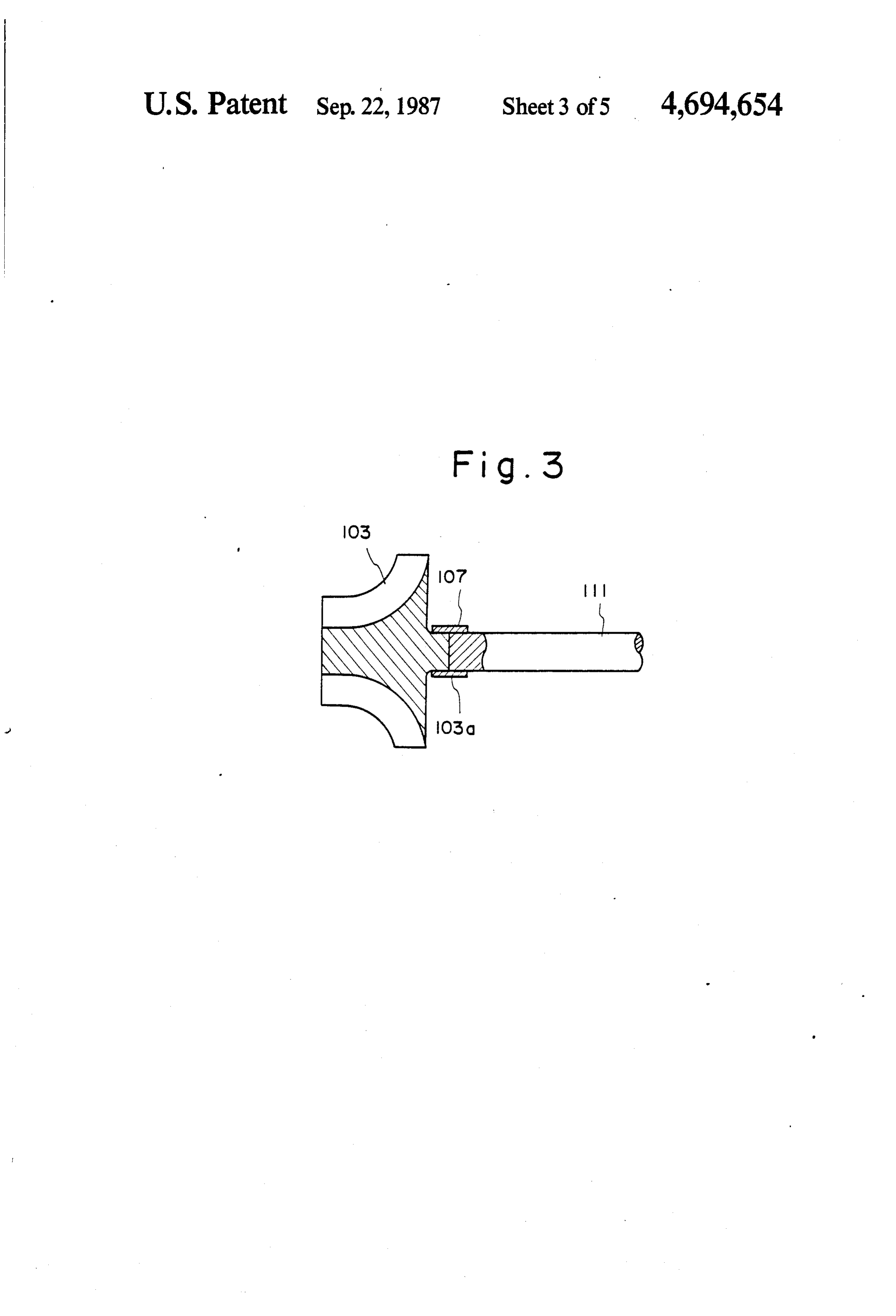
FIG. 2 is a longitudinal cross-sectional view of a 1 is element 8 phase-advancer capacitors; 9 a switching generator device according to the present invention; 50 circuit controlled to be turned on and off by a control FIG. 3 is a cross-sectional view of a coupling mecha signal CS from the control unit 21; and 10 a high-volt nism by which a turbine impeller and a generator rotor age battery 10.
shaft are interconnected in the generator device of the A second exhaust turbine 14 is connected to an outlet invention; 55 end of the first exhaust turbine 3 for recovering residual FIG. 4 is a front elevational view, partly in cross exhaust gas energy. The second exhaust turbine 14 is of section, of a rotor according to another embodiment of the low-speed type for producing most effective com the invention; pressed air when the exhaust gas flows therethrough at FIG. 5 is an enlarged fragmentary cross-sectional a relatively low speed. The second exhaust turbine 14 view of the rotor illustrated in FIG. 4; 60 includes a turbine swirl chamber 14a in which a turbine FIG. 6 is an enlarged side elevational view of the wheel 14b is rotatably disposed. An intake air compres rotor of FIG. 4; sor 15 has a rotatable shaft directly coupled to a turbine FIG. 7 is an enlarged fragmentary cross-sectional shaft 14c of the second exhaust turbine 14. Air com view of a rotor according to still another embodiment; pressed by the intake air compressor 15 is supplied and 65 under pressure into an intake manifold 17 through a FIG. 8 is a circuit diagram of a control circuit for a pipe 16. An exhaust bypass passage or circuit 22 serves reluctance generator in the generator device of the to direct an exhaust gas from the exhaust manifold 2 present invention. directly to the second exhaust turbine 14. A main valve
Page 9
20 is disposed in a passage between the exhaust manifold higher temperature under a higher pressure, and hence 2 and the first exhaust turbine 14 and can be opened and the energy of the exhaust gas having passed through the closed by an actuator 24. A bypass valve 23 is disposed first exhaust turbine 3 and reached the second exhaust in the bypass passage 22 and can be opened and closed turbine 14 is increased. The pressure of air supplied to by an actuator 25. A speed sensor 18 comprising a 5 the intake manifold 17 through the pipe 16 is also in pickup coil, for example, is positioned adjacent to the creased to approach an intercept point. The control unit gear 7b for counting the number of teeth thereofhaving 21 detects such an air pressure increase through the moved past the speed sensor 18. A load detector 19 signal from the air pressure sensor 28, and applies a serves to detect the load imposed on the engine 1 based command signal VC to the inverter 6 to operate the on a rack position or the extent to which an accelerator O induction motor 7 in a maximum power mode. Thus, pedal is depressed. the energy fed back to the engine 1 is maximized to The control unit 21 is responsive to data supplied increase the load on the first exhaust turbine 3. Then, from the speed sensor 18 and the load detector 19 for the speed of rotation of the second exhaust turbine 14 is calculating the amount of an exhaust gas to be fed to the reduced to keep the air pressure in the intake manifold first exhaust turbine 3 and the amount of an exhaust gas 15 17 below the intercept point. When the air pressure in to be fed directed to the second exhaust turbine 14 while the intake manifold 17 is further increased as the load on bypassing the first exhaust turbine 3. Signals indicative the engine 1 is increased, the switching circuit 9 is ener of the amounts of the exhaust gases are supplied from gized to store energy in the battery 10, so that the load the control unit 21 to the actuators 24, 25, respectively, on the first exhaust turbine 3 is increased and the speed for controlling the opening of the main and bypass 20 of rotation of the second exhaust turbine 14 is reduced; valves 20, 23. The control unit 21 is also responsive to thereby lowering the air pressure in the intake manifold output signals from current detectors 26, 27 for issuing 17.
a command signal VC for operating the inverter 6 in a It is generally known that when the engine 1 rotates power or regenerative mode and also for issuing a con at a low speed and under a high load, e.g., when the trol signal CS to turn on or off the switching circuit 9. 25 automobile runs up a sloping road with a low gear, the Denoted at 28 is an air pressure sensor. amount of air drawn from the intake manifold 17 tends When the engine 1 is to be started, the main valve 20 to be lower than an ideal amount of air to be drawn in. is fully open and the bypass valve 23 is fully closed, so Under this condition, the supply of the exhaust gas into that an exhaust gas discharged from the engine 1 will the first exhaust turbine 3 is limited by the main valve flow entirely into the exhaust turbine 3. 30 20, and the bypass valve 23 is opened to supply the When the engine 1 starts rotating, the exhaust gas of exhaust gas directly into the second exhaust turbine 14. a high temperature is fed under pressure into the first Therefore, an amount of compressed air optimum for exhaust turbine 3 to start rotating the turbine wheel 3b fuel combustion is fed under pressure into the intake of the first exhaust turbine 3. The AC generator 4 is manifold 17. Since the second exhaust turbine 14 is of now driven to generate AC electric power having a 35 the low-speed type, an effective amount of air can be high frequency. The AC electric power is converted by supplied thereby into the engine.
the converter 5 into DC electric power which is then The main valve 20 and the bypass valve 23 are converted by the inverter 6 into an alternating current opened and closed under the control of the control unit of a low frequency capable of energizing the induction 21. The control unit 21 reads data from the speed sensor motor 7. However, since the speed of rotation of the 18 and the load detector 19, computes the extent to first exhaust turbine 3 is low at this time, the output which the main valve 20 and the bypass valve 23 are to power from the AC generator 4 is small and cannot be opened to meet the speed of and the load on the energize the induction motor 7. engine 1 at the time, and issues control signals indicative As the speed of rotation of the engine 1 is increased to of the extent of such valve openings to the correspond discharge an exhaust gas under a higher pressure at a 45 ing actuators 24, 25.
higher temperature, the output power from the AC Generator devices according to preferred embodi generator 4 is increased. When the output power from ments of the present invention will be described with the inverter 6 becomes greater than a counterelectro reference to FIGS. 2 through 8.
motive force of the induction motor 7, the inverter 6 In FIG. 2, an exhaust turbine 101 comprises a turbine operates in a power mode thereby to drive the induction SO housing 102 having a scroll 102a and a turbine wheel or motor 7. Since the induction motor 7 drives the output impeller 103 rotatably disposed in the turbine housing shaft 1a in a direction to increase the output therefrom, 102. The scroll 102a is coupled to the exhaust pipe of an the energy of the exhaust gas is recovered and fed back internal combustion engine for introducing an exhaust to the output shaft 1a of the engine 1. gas from the exhaust pipe to rotate the turbine wheel When the engine 1 operates under a partial load, a 55 103 with the energy of the exhaust gas. The exhaust gas considerable amount of energy remains in the exhaust having rotated the turbine wheel 103 is discharged gas which has rotated the first exhaust turbine 3. The through an axial outlet port 102b and an exhaust pipe residual exhaust energy that has not been recovered by coupled therewith.
the first exhaust turbine 3 then passes through the sec On an inner wall surface of the scroll 102a, there is ond exhaust turbine 14, whereupon the turbine wheel 60 mounted a heat-insulative wall 105 made of a heat 14b starts to rotate. The intake air compressor 15 cou resistant metal, such as stainless steel, with a heat insula pled with the turbine wheel 14b is then driven to supply tor 104, such as of ceramic fibers, interposed between compressed air through the pipe 16 into the intake mani the wall 105 and the inner wall surface of the scroll fold 17. Under the partial engine load, however, no 102a. A heat-insulative guide 106 made of a heat-insula significant amount of air is fed under pressure into the 65 tive material, such as ceramics, is disposed on an inner intake manifold 17. When the engine 1 rotates at a surface of an tubular exhaust portion of the housing 102 higher speed under a full load at the time the automobile for preventing thermal radiation of the exhaust gas runs at a high speed, the exhaust gas is discharged at a through the housing 102.
Page 10
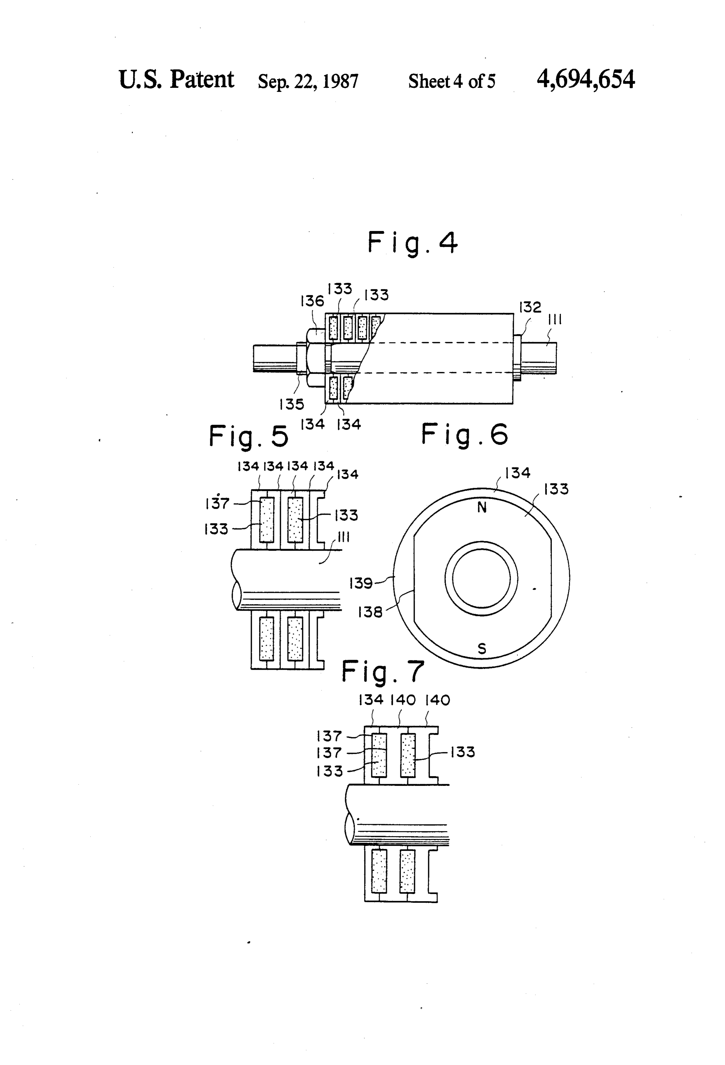
The turbine wheel 103 is made of ceramics such as The rotor includes a shoulder 132 integral with the silicon nitride having a high strength against heat, the rotor shaft 111, magnets 133, housing members 134 turbine wheel 103 having an integral wheel shaft 103a. housing the magnets 133, a threaded portion 135 on the A generator 110 includes a rotor shaft 111 disposed rotor shaft 111, and a nut 136 threaded over the coaxially with the wheel shaft 103a, the rotor shaft 111 threaded portion 135. The housing members 134 as they being integrally formed of ceramics with the turbine are held axially together are retained on the rotor shaft wheel 103 and the wheel shaft 103a. The wheel shaft 111 between the nut 136 and the shoulder 132. Each of 103a and the rotor shaft 111 may be separately formed the magnets 133 is made of a rare earth metal having a of ceramics as shown in FIG. 3. With such an alterna high magnetic force and a high coercive force. As tive, they are interconnected by a connecting sleeve 107 10 shown in FIG. 6, each magnet 133 is substantially disk and made of a metal such as Kovar having substantially shaped with a central hole defined therein. After the the same coefficient of thermal expansion as that of magnet 133 has been magnetized, it is accommodated in ceramics, the connecting sleeve 107 being first fitted recesses in the confronting pair of housing members over the wheel shaft 103a and the rotor shaft 111 and 134. As illustrated in FIGS. 5 and 6, each housing mem then joined to them by being metallized. It is preferable 15 ber 134 comprises a disk-shaped member having a cen that the rotor shaft 111 beformed of a ceramics material tral hole in which the rotor shaft 111 is fitted. With the such as cermet having a large Young's modulus. A housing members 134 alternately oriented in opposite bearing housing 108 is fixed to a side of the turbine directions, the paired housing members 134 define a housing 102 with a heat insulator 109 interposed there hollow space 137 serving to accommodate the magnet between. The bearing housing 108 is secured in position 20 133. The housing members 134 are made, such as of by an attachment plate 161 fastened by a bolt 162. The PSZ (partially stabilized zirconia), having a strength to generator 110, in turn, is secured in position to the bear withstand high-speed rotation. Since PSZ has a deflec ing housing 108 by bolts, such as 112. tive strength of 130 Kg/mm or more and a modulus of The generator 110 comprises, in addition to the rotor elasticity comparable to that of iron, it also has a shaft 111, a magnet rotor 114 fitted over the rotor shaft 25 strength against fastening forces. The housing members 111 and made of a rare earth metal capable of producing 134 have flat surfaces 138 in their inner spaces for align stroke magnetic forces, stator coils 115a and stator coils ing the magnets 133 housed therein, and marks 139 11.5b mounted on the magnet rotor 114 in diametrically impressed on outer surfaces thereof. The threaded por opposite positions, and a bearing housing 116 by which tion 135 may be formed directly on the rotor shaft 111 one end of the rotor shaft 111 is rotatably supported. 30 or may be mounted by metallizing or force-fitting an The magnet rotor 114 produces much stronger mag alloy such as one of titanium. After the housing mem netic forces than those of ordinary magnets, and having bers 134 and the magnets 133 have been fitted over the a residual flux density Br ranging from 5,000 to 9,500 rotor shaft 111 as shown in FIGS. 4 and 5, the nut 136 wb/cm and a coercive force ranging from 4,500 to 9,500 is threaded over the threaded portion 135 to fasten the A/m. Although the magnet motor 114 is best suited for 35 housing members 134 and the magnets 133. The mag use as a magnet, it could not be used solely as a magnet nets 133 have a thickness slightly larger than the axial rotor in a high-speed generator subjected to large cen depth of the hollow space in the combined pair of hous trifugal forces since the magnet rotor 114 has quite a ing members 134. Therefore, when fastened together by small deflective and tensile strength. Therefore, the the nut 136, the magnets 133 are held under axial com magnet rotor 114 is firmly mounted on the rotor shaft 40 pression.
111 by ring-shaped holder plates 113 held against axial FIG. 7 shows a rotor according to still another em ends of the magnet rotor 114 and made of a high bodiment of the present invention. The rotor of FIG. 7 strength material such as titanium or an aluminum alloy. is of substantially the same construction as the rotor of A carbon wire 163 such as one made of carbon fibers, FIGS. 3 through 6, except that there are two types of is coiled around the magnet rotor 114 and connected to 45 housing members used. More specifically, the housing the holder plates 113, the coils of the carbon wire 163 members 134 shown in FIG. 4 are disposed at the ends having a layer thickness in the range of from 1 mm to 2 of the rotor, but housing members 140 having recesses defined in opposite surfaces thereof are mounted on the
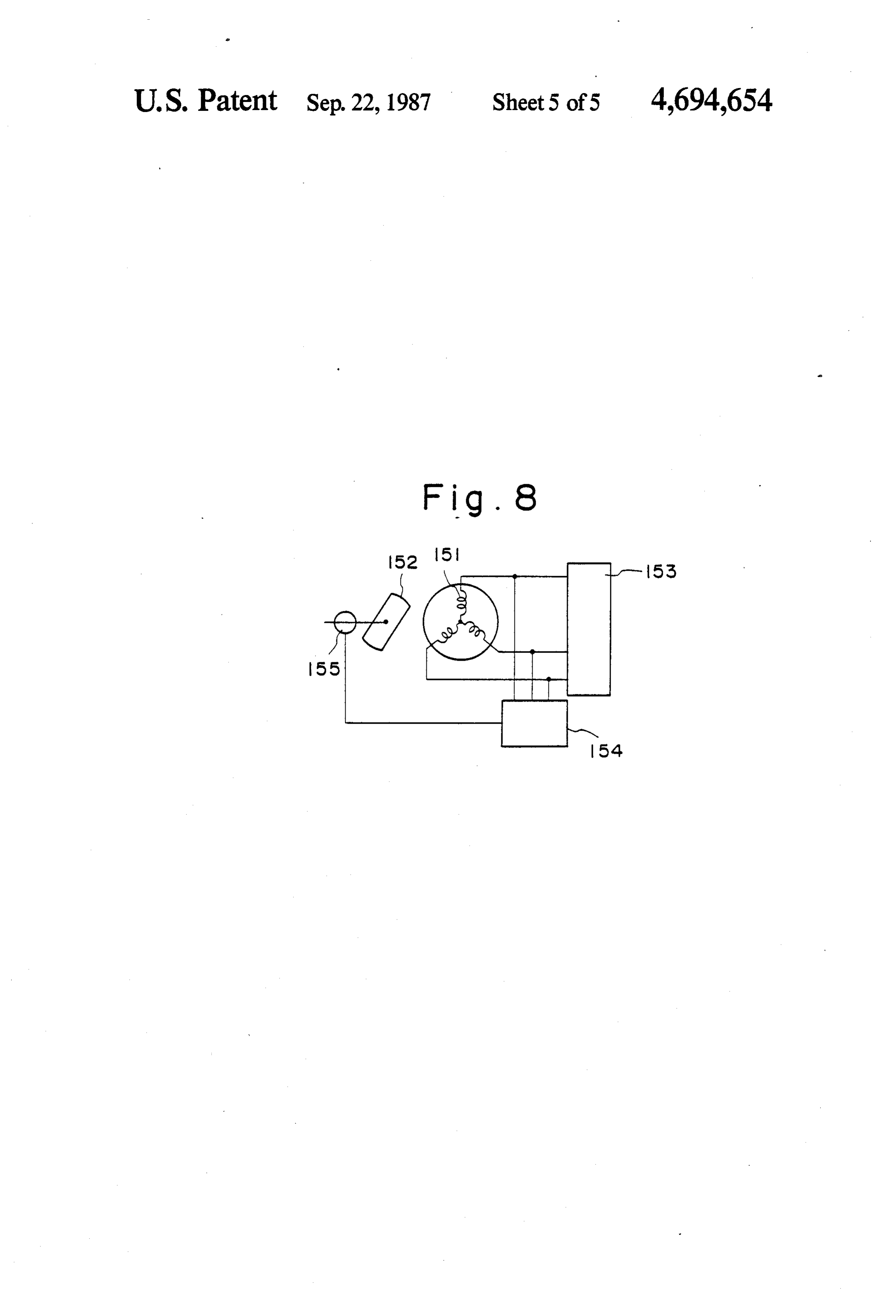
Each of the bearing housings 108, 116 accommodate rotor shaft axially between the housing members 134. a fixed bearing 120 and a floating bearing 121. The axial 50 A control circuit for controlling the generator device ends of the rotor shaft 111 are rotatably supported by of the present invention will be described with refer the floating bearings 121 which are rotatably disposed ence to FIG. 8. According to the present invention, a in the fixed bearings 120, respectively. The fixed bear reluctance generator can be used in place of the syn ings 120 and the floating bearings 121 have respective chronous generator using permanent magnets shown in lubricant passages 120a, 121a and the bearing housings 55 FIGS. 1 through 7. The reluctance generator of the 108, 116 have main lubricant conduits 108a and 116.a for invention will briefly be described. It is assumed that a supplying a lubricant to lubricate and cool sliding sur rotor composed of permanent magnets or a field coil faces of the bearings 120, 121 and the sliding surfaces of rotates within a three-phase armature winding. If an the floating bearings 121 and the rotor shaft 111. induced armature current is in phase with an electromo The floating bearings 21 are prevented by snap rings 60 tive force, then a magnetomotive force is generated by 122 from sliding in axial directions. Designated by 123 is the armature current in a position which is 90 delayed a thrust bearing for the rotor shaft 111, and 125 a posi from a magnetic flux produced by the permanent mag tioning ring therefor. The bearing assembly on the nets or the field coil.
righthand end (FIG. 2) of the rotor shaft 111 is covered In view of this, a current which is 90' advanced in by a cover 124 with an oil seal ring 126 mounted 65 phase from a no-load induced electromotive force is therein. Cover 124 supports the rotor shaft 111. generated at all times to provide a condition equivalent FIGS. 4 through 6 are illustrative of a rotor accord to the adjustment of a field current in an ordinary syn ing to another embodiment of the present invention. chronous generator. Thus, a reluctance generator hav
Page 11
ing the same function as that of the synchronous genera produce high output at a high efficiency. Since the tor can be achieved without any field coil and perma magnet housing is composed of a plurality of housing nent magnets. members of identical shape held together and fastened The control circuit shown in FIG. 8 for such a reluc under axial compression to the rotor shaft, the rotor can tance generator includes armature coils 151 of the reluc 5 therefore be manufactured in a simple process and at a tance generator, a rotor 152, a load 153, a source 154 of reduced cost.
advanced-phase reactive power, and a rotational posi The turbine wheel 103, the wheel shaft 103a, and the tion sensor 155. The rotational position sensor 155 de rotor shaft 111 are constructed of ceramics, and hence tects a rotation 21 position of the rotor 152 for enabling are lightweight. The shafts 103a, 111 are also prevented the source 154 to supply an excitation current to the O effectively from being deformed under centrifugal armature coils 151. Rotation of the rotor 152 causes the forces. The generator device is therefore highly effi armature coils 151 to induce electromotive forces for thereby supplying electric power to the load 153. cient in operation. Where the rotor shaft 111 is formed The thermally insulative engine of the present inven of a ceramics material having a large Young's modulus, tion is capable of supplying air under pressure to the 15 itit isis prevented rotated at from being deformed eccentrically when a high speed.
engine cylinders when the engine rotates at a low speed and under a high load, unlike the conventional engine in and the rotor shaft 111wheel
Where the turbine 103, the wheel shaft 103a, which compressed air can be supplied to the engine ics, they are not requiredaretoformed integrally of ceram cylinders only when the engine rotates at a high speed are less susceptible to malfunctioning. together, and be assembled and under a high load. When the engine rotates at a Furthermore, a reluctance generator using perma medium speed and under a medium load or at a medium nent magnets or a field coil and rotatable at high speeds speed and under a low load, at which time it is not can be provided.
necessary to supply air under pressure to the engine cylinders, the exhaust energy can effectively be recov Although certain preferred embodiments have been ered and fed back to the engine output shaft. The ar 25 shown and described, it should be understood that rangement for recovering the exhaust energy and feed many changes and modifications may be made therein ing it back to the engine output shaft is subjected to a without departing from the scope of the appended lower frictional loss than would be the conventional claims.
mechanical exhaust energy recovery device. In addi What we claim is:
tion, any loss in the recovered energy due to an electric 30 1. An exhaust energy recovery and generator device circuit resistance can be reduced by increasing the cir for a thermally insulative engine having an exhaust cuit voltage. Therefore, the combustion efficiency of passage and an output shaft, the device comprising: the engine can be highly increased. The energy recov (a) a first exhaust turbine disposed in the exhaust ery device of the invention is quite simple in overall passage of the thermally insulative engine and ro construction. 35 tatable by the energy of an exhaust gas discharged As described above, the exhaust gas emitted from the from the thernally insulative engine, said first ex internal combustion engine is introduced into the scroll haust turbine having a wheel and a wheel shaft; 102a of the exhaust turbine 101 and acts on the turbine (b) a generator having a rotor shaft coupled coaxially wheel 103, and then is discharged out of the outlet port with the wheel shaft of said first exhaust turbine; 102b. At this time, the turbine wheel 103 is rotated at a 40 (c) a converter operatively connected to said genera high speed by the energy of the exhaust gas. The rota tor for converting alternating current into direct tion of the turbine wheel 103 is directly transmitted to current;
the rotor shaft 111 integral with the wheel shaft 103a. (d) an inverter operatively connected to said con Therefore, the magnet rotor 114 rotates at a high speed verter for converting direct current into alternat for highly efficient power generation. 45 ing current;
Since the magnet rotor 114 is made of a rare earth (e) a motor having a rotatable shaft and drivable by metal, it has a strong magnetic force, and the generator said generator via said converter and said inverter; can produce a large amount of electric power when the (f) means connecting the rotatable shaft of said motor rotor 114 rotates at a high speed. to the output shaft of the thermally insulative en The rare earth magnet rotor 114 is covered on its 50 gine, whereby the energy of the exhaust gas recov outer circumference with the carbon wire 133, and ered by said first exhaust turbine can be fed back to hence can be prevented from being displaced or de the output shaft of the thermally insulative engine formed radially outwardly. The magnet rotor 114 can through said generator, said converter, said in also be prevented by the holder plates 113 from being verter and said motor;
displaced or deformed in axial directions. Accordingly, 55 the magnet rotor 114 which is made of a mechanically (g) a body of silicon steel fitted over the rotor shaft of weak rare earth metal is of a thin configuration and a the generator; and high strength by being surrounded by the holder plates (h) a stator coil, having a winding, for passing an 33 and the carbon wire 33. armature current which is 90 advanced in phase Since the magnet rotor 114 is of a cylindrical shape 60 through the winding to generate a no-load induced fitted over the rotor shaft 111, it produces a reduced electromotive force, said generator thereby serving windage loss and thus serves as an ideal generator rotor. as a reluctance generator. The rotor shown in FIGS. 3 through 5 includes mag 2. A device according to claim 1, wherein the turbine nets of a rare earth metal accommodated in the housing wheel of said exhaust turbine is constructed of ceramic fitted over the rotor shaft, and has a high magnetic force 65 material.
and can withstand high-speed rotation. Therefore, the 3. A device according to claim 1, wherein the rotor rotor is effective for use in a high-speed generator, and shaft of said generator is constructed of ceramic mate the generator with the rotor incorporated therein can rial.
Page 12
4. A device according to claim 1, wherein the turbine aligned in an axial direction so that a first plane wheel, the wheel shaft, and the rotor shaft are con passes through the rotor shaft of said generator and structed integrally of ceramic material. the first magnetic pole of each of said magnets and 5. A device according to claim 1, further including oil a second plane passes through the rotor shaft of floating bearings rotatably supporting the rotor shaft of 5 said generator and the second magnetic pole of said generator. each of said magnets.
6. A device according to claim 1, further including: 8. A device according to claim 1, wherein the engine a magnet rotor of a rare earth metal fitted over the has an intake manifold and the device further including: rotor shaft of said generator, said magnet rotor a second exhaust turbine connected to said first ex having a circumferential surface; 10 haust turbine and the exhaust passage of the ther holder members mounted on the rotor shaft and held mally insulative engine and rotatable by the energy against opposite ends of said magnet rotor; and of exhuast gas discharged from the thermally insu a carbon wire coiled around the circumferential sur face of said magnet rotor. lative engine and from said first exhaust turbine; 7. A device according to claim 1, further comprising 15 an intake air compressor connected to said second a magnet housing fitted over the rotor shaft of said exhaust turbine for supplying compressed air to the generator, including: intake manifold of the thermally insulative engine; housing members held axially together, each of said and housing members having a central hole through control means for selectively connecting the exhaust which the rotor shaft extends and a recess defined 20 passage of the thermally insulative engine to said in at least one surface thereof; and first and second exhaust turbines and for regulating magnets, each of said magnets disposed in the reces said motor in accordance with predetermined con ses of a pair of said housing members and having ditions,
first and second magnetic poles, said magnets being
Provenance
- Collection
- Cited prior art
- Original PDF
- patentimages.storage.googleapis.com →
- Filed
- 1984-10-29
- Pages
- 12
- Method
- pdftotext (the PDF's own text layer) + pdftoppm 300dpi page scans
- Source
- Google Patents bibliographic record
- Granted
- 1987-09-22
- Inventors
- Hideo Kawamura; Isuzu Motors Ltd
- Transcribed from
- patentimages.storage.googleapis.com →