patent · US5765538
Pump device for a fuel vapor retention system of an internal combustion engine
16 June 1998
Page 1 — bibliographic record
United States Patent (19) 11 Patent Number: 5,765,538 Krimmer et al. 45 Date of Patent: Jun. 16, 1998 54 PUMP DEVICE FOR A FUEL WAPOR 52 U.S. C. ............................................. 1231516; 123/519 RETENTION SYSTEM OF AN INTERNAL 58) Field of Search ................................... 123/516, 518. COMBUSTON ENGINE 123/519, 520, 521: 417/413.1 75 Inventors: Erwin Krimmer, Pluederhausen; 56 References Cited Helmut Denz, Stuttgart; Wolfgang U.S. PATENT DOCUMENTS
Schulz. Bietigheim-Bissingen; Ernst
Wild, Oberriexingen; Winfried Kuhnt, 5,499,614 3/1996 Busato et al. ........................... 123/520 Stuttgart; Helmut Schwegler. 5,603,359 2/1997 Harris.............. ... 123/519 Pleidelsheim; Andreas Blumenstock, 5,635,630 6/1997 Dawson et al....... ... 123/520 Ludwigsburg; Tilman Miehle, Kernen; 5,651,350 7/1997 Blomquist et al. ..................... 123/520 Manfred Zimmermann, Bad Primary Examiner-Thomas N. Moulis
Rappenau, all of Germany Attorney, Agent, or Firm-Edwin E. Greigg; Ronald E. Greigg 73 Assignee: Robert Bosch GmbH. Stuttgart,
Germany 57 ABSTRACT (21) Appl. No.: 793,581 A pump device for performing a leak diagnosis of a fuel 22) PCT Filled: May 10, 1996 vapor retention system. The pump device is provided for a fuel vapor retention system of an internal combustion 86) PCT No.: PCT/DE96/00815 engine, having a pump membrane driven by an electromag net and a magnetic armature, which membrane defines a
S371 Date: May 15, 1997 supply chamber that has valve devices, wherein a first valve S 102(e) Date: May 15, 1997 can be connected to ambient air via a delivery line and can be connected via a second valve to a feed pipe that has an 87 PCT Pub. No.: WO97/02421. adsorption filter, and having a stop valve between the PCT Pub. Date:Jan. 23, 1997 delivery line and the feed pipe, which valve is embodied so that it can be electromagnetically actuated. The pump device 30 Foreign Application Priority Data according to the invention is provided for a fuel vapor Jun. 30, 1995 DE Germany ........................ 195239350 retention system of an internal combustion engine. (51 Int. Cl. .................... FO2M 37/04 14 Claims, 6 Drawing Sheets
sSls
Page 2
Drawing sheet — no readable text.
Page 3
Drawing sheet — no readable text.
Page 4
Drawing sheet — no readable text.
Page 5
Drawing sheet — no readable text.
Page 6
Drawing sheet — no readable text.
Page 7
Drawing sheet — no readable text.
Page 8
PUMP DEVICE FOR A FUEL WAPOR in the sleeve so that the determination of the size of the RETENTION SYSTEM OF AN INTERNAL leakage opening is only possible in an imprecise manner. COMBUSTON ENGINE A pump device driven by a vacuum prevailing in the intake pipe is usually provided in the vicinity of the adsorp
PRIOR ART tion filter, which is preferably disposed in the region of the The invention is based on a pump device for a fuel vapor fuel tank of a vehicle. The fuel tank is ordinarily accom modated in the rear region of the vehicle, resulting in a retention system of an internal combustion engine. A pump relatively device has already been disclosed (WO 94/15090) which is adsorptionlong vacuum hose from the pump device on the filter to the intake pipe of the engine. Since a leak provided for leak testing a fuel vapor retention system in O or a tear in the vacuum hose would put the pump device out order to deliver a definite volume of air via a ventilation connection of an adsorption filter to a fuel tank of the engine in of commission, a vacuum hose of this kind must be placed by means of the pump device so that a pressure increase is a particularly protected manner on the bottom of the produced. In order to determine whether the fuel vapor vehicle, though, which creates considerable costs. retention system is pressure tight, some time is allowed to 15 The pump device driven by the vacuum of the intake pipe pass after the pressure increase finishes in order to indicate has the disadvantage, moreover, that a leak diagnosis can a leak when there is a pressure decrease in the fuel vapor only be carried out when there is a sufficient vacuum in the retention system, wherein the time elapsed for the pressure intake pipe. The leak diagnosis is therefore essentially decrease is a measure for the size of the leakage opening. limited to the idling range of the engine, which is charac Furthermore, the fuel vapor retention system includes a terized by a high vacuum. In the upper partial load range or regenerating valve provided between the adsorption filter in the full load range as well as when the engine is switched and an intake pipe of the engine to introduce the fuel vapor off. there is not sufficient vacuum to drive the pump device temporarily stored in the adsorption filter into the intake pipe so that a leak diagnosis is not possible. by means of the regenerating valve. Furthermore, during the leak diagnosis. air is aspirated The pump device disclosed in the prior art has a pump 25 from the pump chamber into the intake pipe with each membrane which is acted upon alternatingly with vacuum switching procedure of the on-off valve, at the transition and ambient pressure to drive the pump device. When the from ambient pressure to vacuum. This can lead to fluctua engine is running, the vacuum is taken from the intake pipe tions of the air quantity flowing in the intake pipe, though, of the engine via a vacuum hose, and via an on-off valve, which is already apportioned by a throttle mechanism dis which is embodied for example in the form of a solenoid posed in the intake pipe, upstream of the withdrawal point valve, is delivered to a pump chamber of the pump device, of the vacuum connection so that in particular in the critical which chamber is defined by the on-off valve and the pump region of the idling of the engine, the pulsating introduction membrane. By switching the on-off valve, vacuum and of air can produce difficulties in the preparation of a fuel-air ambient pressure are alternatingly set in the pump chamber. ratio to be precisely maintained in the combustion chambers When the pump chamber is acted upon with vacuum, the 35 of the engine.
pump membrane moves counter to the compression force of ADVANTAGES OF THE INVENTION a pump spring, wherein air flows out of a delivery line into a supply chamber disposed opposite the pump chamber, The pump device according to the invention, has the which supply chamber is closed off by the pump membrane advantage over the prior art that a leak diagnosis can be and two stop valves, a suction relief valve and a pressure carried out at any time in a simple manner with the pump relief valve. With the subsequent impingement of ambient device according to the invention, independent of the opera pressure on the pump chamber, the pump membrane moves tional regions of the engine and even when the engine is in the opposite direction, supported by the compression switched off. The vacuum connection on the pump device force of the pump spring, wherein the air enclosed in the that is required in the prior art can be eliminated, by means supply chamber is compressed. When a certain excess 45 of which the pump device according to the invention is more pressure is reached in the supply chamber, the pressure relief fail-safe and more reasonably priced. It is particularly valve opens so that the ambient air compressed in the supply advantageous that with the pump device according to the chamber flows into the ventilation connection of the adsorp invention, even extremely small leakage openings of less tion filter via the feed pipe in order to produce a pressure than a millimeter in diameter can be detected. The leak increase in the fuel tank. 50 diagnosis can be advantageously achieved by the pump In the prior art indicated, the switching process by means device according to the invention, without an air supply into of the on-off valve is controlled by a so-called reed switch, the intake pipe thus preventing a disadvantageous influence which is known to one skilled in the art. The reed switch is on the mixture preparation.
actuated by magnetic forces and is attached for example to Advantageous improvements and updates of the pump an outer surface of a sleeve in which a pump plunger 55 device are possible by means of the measures set forth attached to the pump membrane is guided so that the pump hereafter. The pump device according to the invention plunger can move longitudinally. A permanent magnet is distinguishes itself, moreover, by means of a particularly provided on an end of the sleeve opposite from the reed compact construction in which the electrical components are switch in order to produce a corresponding change of the accommodated in a protected manner in the housing so that magnetic field of the permanent magnet on the reed switch when water or fuel penetrates into the pump device, a failure depending on the position of the pump plunger in the sleeve of the pump device need not be feared. Furthermore, the so that when the end position of the pump plunger is high pump frequency of the pump device that is provided, in reached, the reed switch is correspondingly actuated. The connection with a particularly precise position determina position determination of the pump plunger by means of the tion of the pump membrane by means of contact tabs reed switch, though, is connected with high tolerances and 65 provided and a contact disk attached to the pump plunger, thus does not permit a precise determination of the position permits a precise determination of extremely small leakage of the pump membrane or the position of the pump plunger openings, wherein the operating noise of the pump device is
Page 9
only slight. It is particularly advantageous that essential The regenerating valve 10 is closed for leak testing the control functions of the pump device are executed automati fuel vapor retention system 1. Then, a definite volume of air cally by means of a contact plate in the housing, outfitted is supplied to the fuel tank 4 by means of the pump device with electrical components so that among other things, only 2 via the adsorption filter 6 in order to produce a pressure a few connecting lines to an external electronic control increase. After the pressure increase finishes, some time is device are required. Furthermore, the pump device accord allowed to pass until the pressure has decreased again, ing to the invention also permits the detection of larger possibly due to a leak in the fuel vapor retention system 1, leakage openings of the fuel vapor retention system, which wherein the time elapsed for the pressure decrease is a can, for example, be attributed to a missing gas cap on a fuel measure for the size of the leakage opening in the fuel vapor tank of the engine. 10 retention system 1. This leak testing of the fuel vapor retention system 1, also known as the excess pressure
BRIEF DESCRIPTION OF THE DRAWINGS method, permits leakage openings to be detected on an order of magnitude of less than one millimeter in diameter. If the
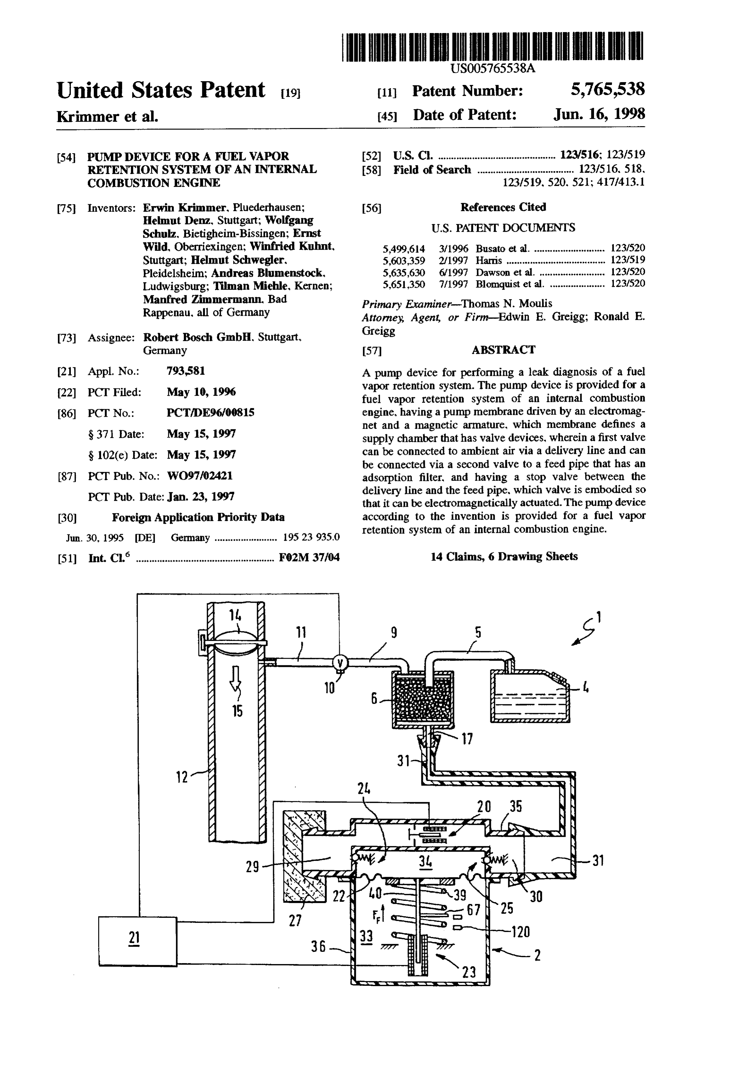
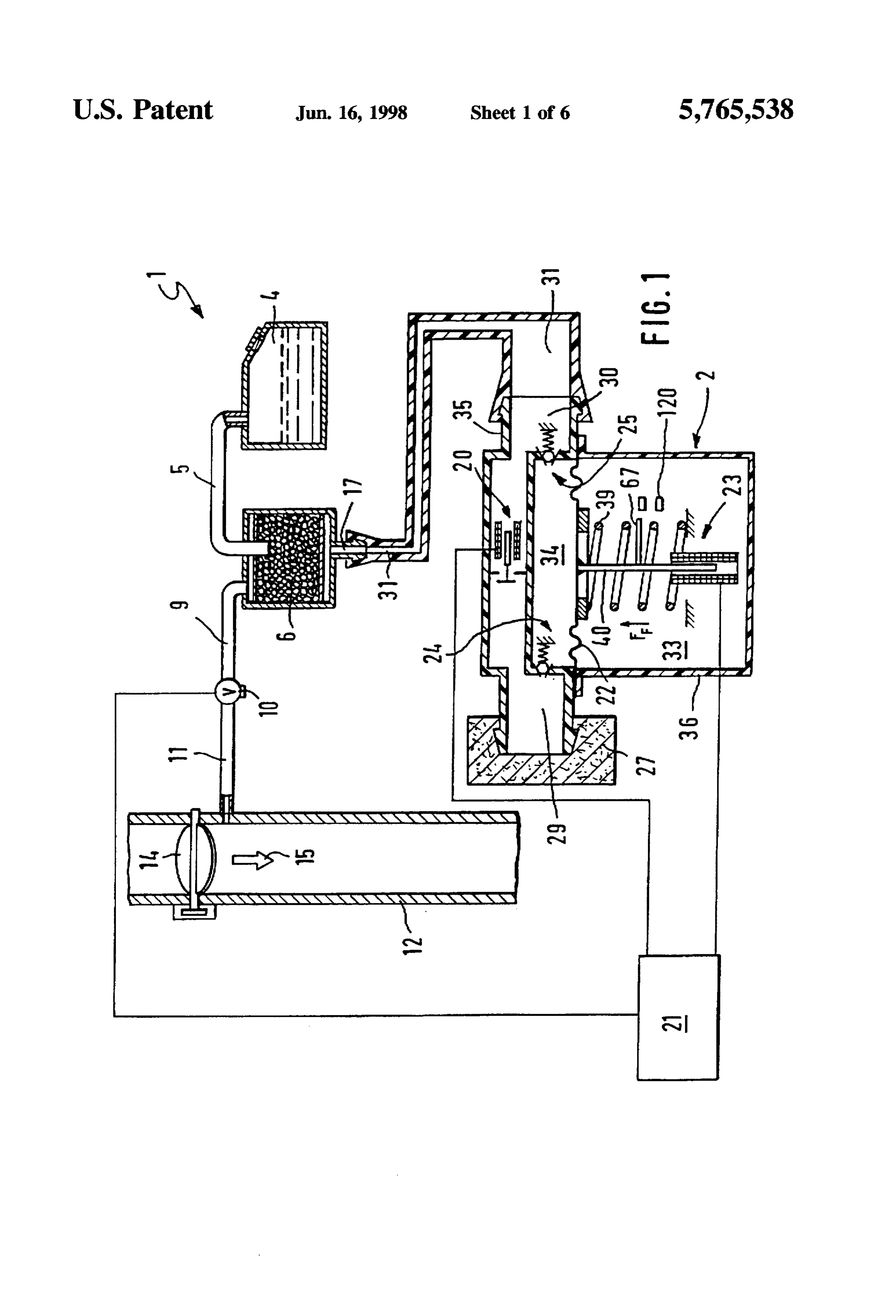
An exemplary embodiment of the invention is shown in excess pressure in the fuel vapor retention system 1 does not simplified fashion in the drawings and explained in detail in 15 reach the pump membrane 22 even after a particular number the description below. of pump strokes, then a large leak or a missing gas cap on FIG. 1 shows a fuel vapor retention system for an internal the fuel tank 4 can be indicated. In the event of this, it is combustion engine, which system has a pump device possible for the electronic control device 21 connected to the according to the invention that is depicted in a schematically pump device 2 to trigger an indicator device, for example on simplified fashion, the inside of the vehicle, to inform the driver in this manner FIG. 2 shows a side view of the pump device according about the malfunction occurring in the fuel vapor retention to the invention, system 1.
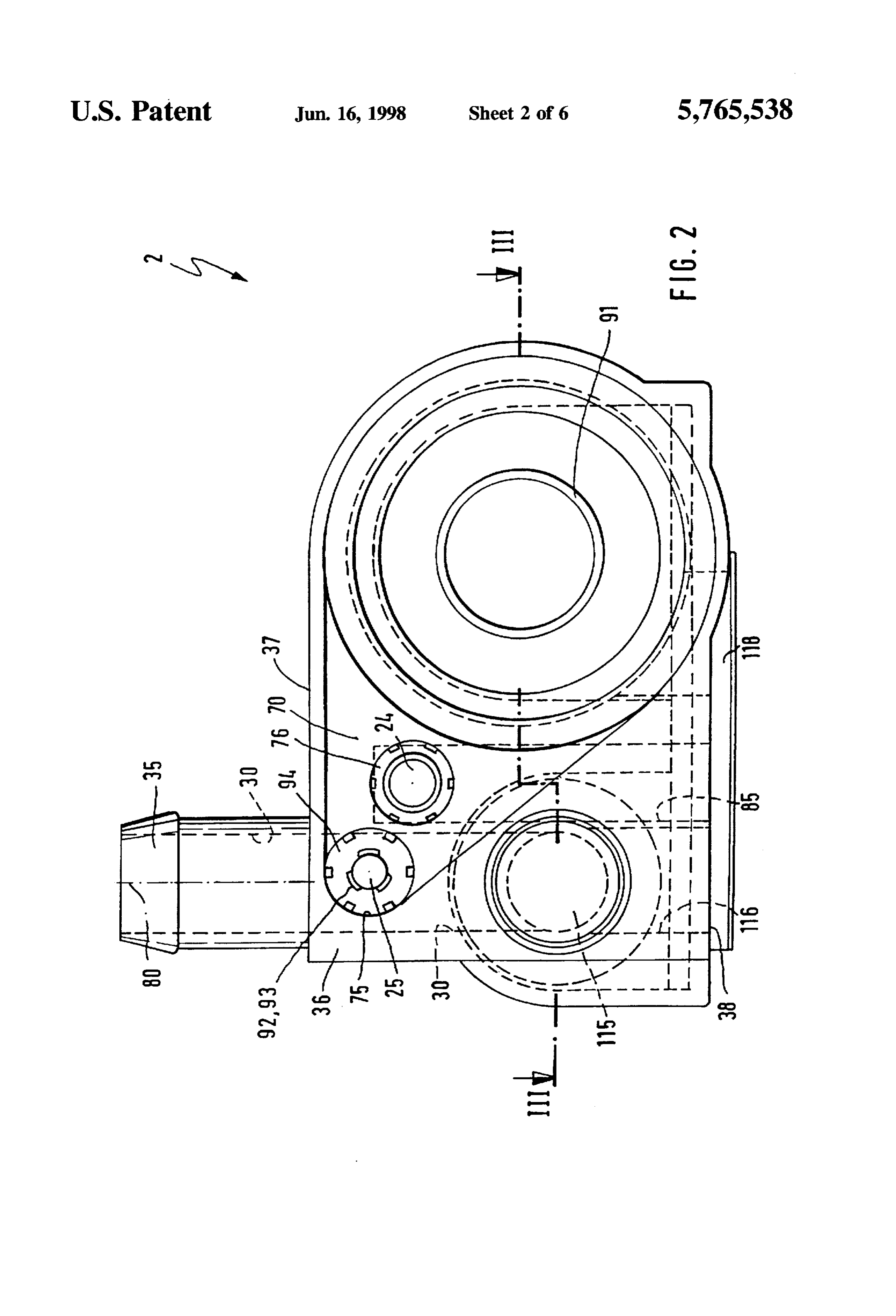
FIG. 3 shows a section along a line III-III in FIG. 2, The excess pressure required for testing purposes is supplied
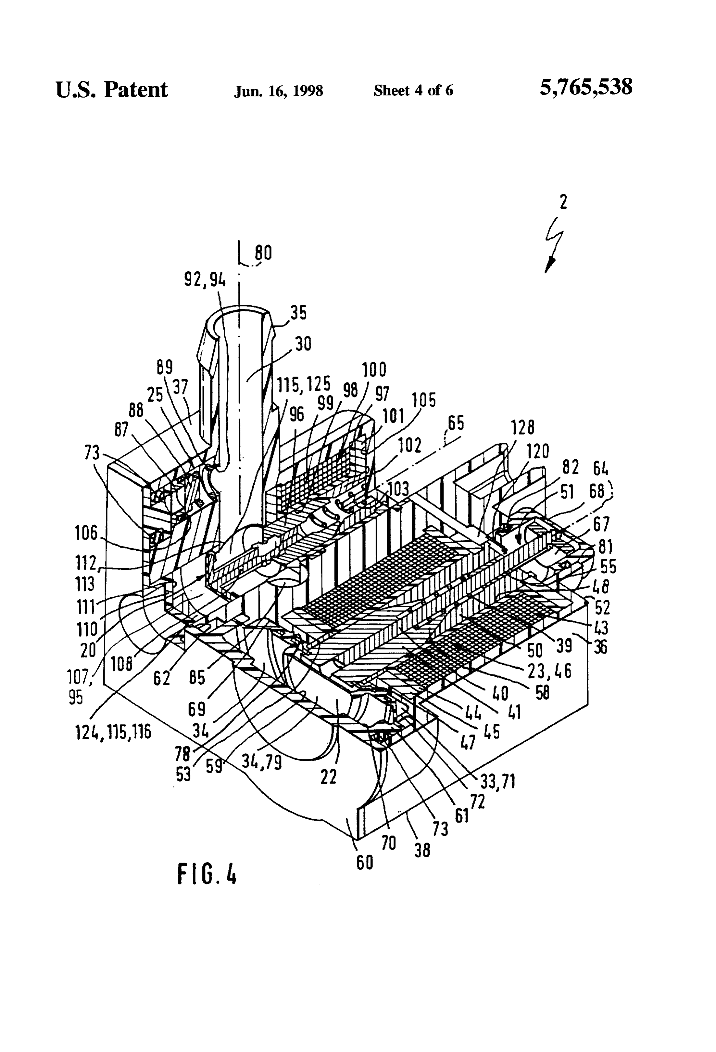
FIG. 4 shows a partial cutaway view of the pump device which aspirates by the pump device 2 according to the invention, according to the invention in a perspective representation, 25 pumping ambient air into a delivery line 29 in the process, for example via an ambient air filter 27
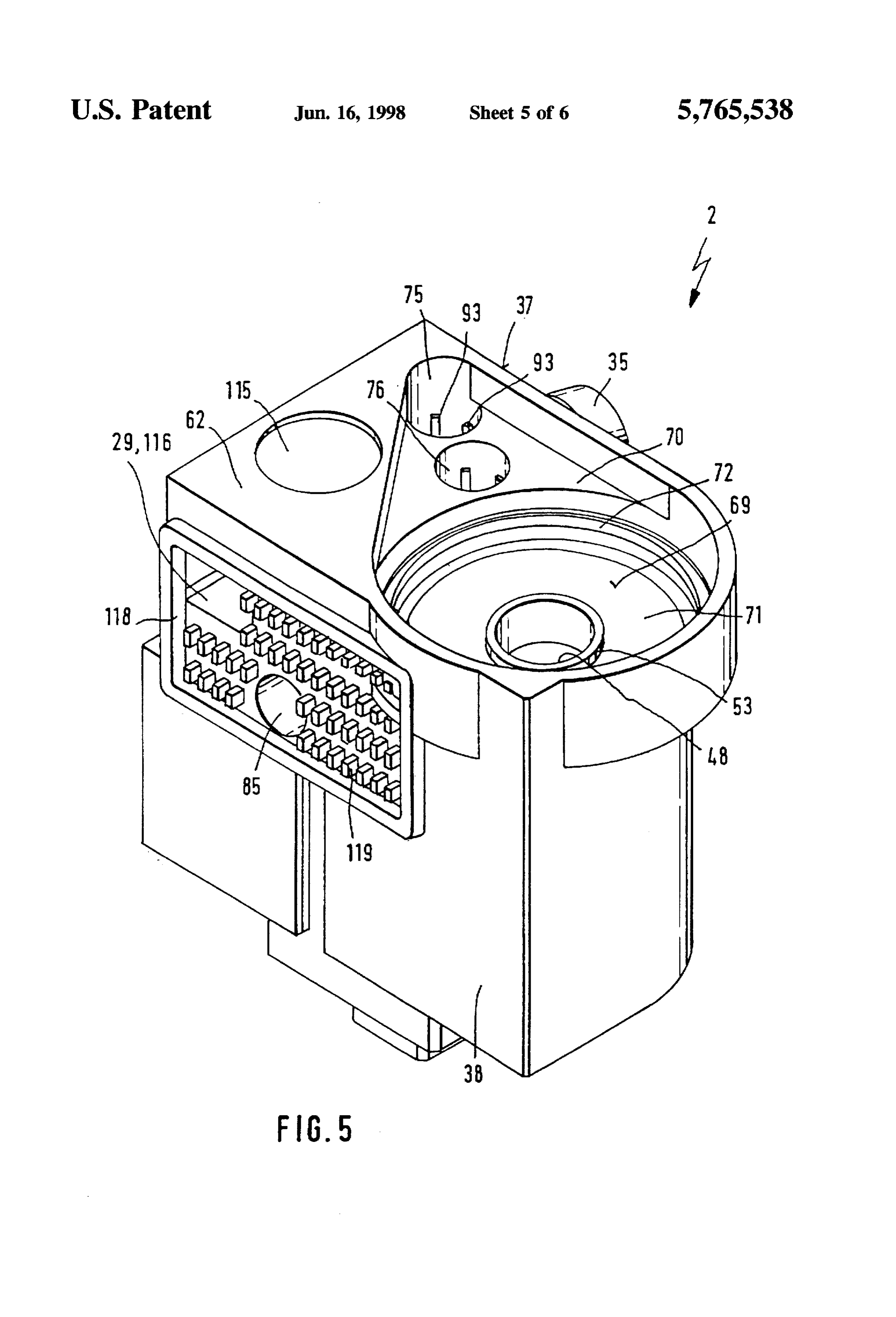
FIG. 5 shows a perspective rear view of the pump device disposed in or on a housing 36 of the pump device 2, in order according to the invention, and to then pump this air at increased pressure into a feed pipe FIG. 6 shows a perspective view of a component of the 30. The feed pipe 30 is connected to the ventilation con pump device according to the invention. nection 17 of the adsorption filter 6, for example via a
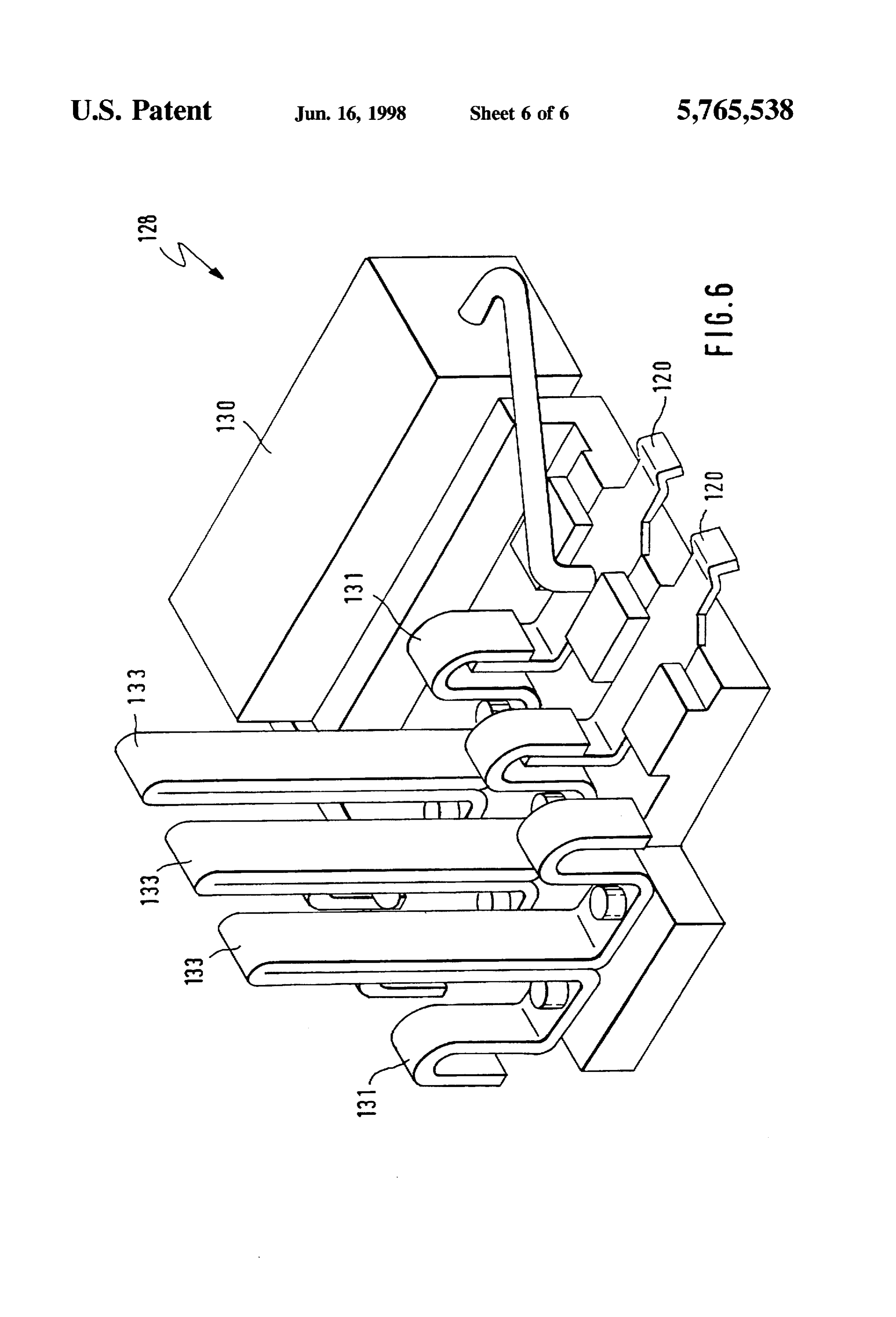
DESCRIPTION OF THE EXEMPLARY
separate line 31. The pump device 2 is composed of a
EMBODMENT
number of individual components that are functionally sepa rate from one another, which are accommodated in the
FIG. 1 shows a fuel vapor retention system, which is housing 36 and essentially comprise a pump part 23 and a identified with 1... which is for an internal combustion engine 35 stop valve 20 that can be electromagnetically actuated. The not shown in detail, and is equipped with a pump device 2 pump part 23 is provided for compressing ambient air and is according to the invention depicted in a schematically composed of a pump membrane 22, a pump plunger 40, a simplified fashion, which produces an excess pressure for device 67. 120 that detects the position of the pump plunger diagnostic purposes in the fuel vapor retention system 1. The 40, a pump spring 39, and a valve device constituted by a fuel vapor retention system 1 also includes a fuel tank 4 for suction relief valve 24 and a pressure relief valve 25. The supplying the engine with fuel and an adsorption filter 6 pump membrane 22 divides the pump part 23 into a pump connected to the fuel tank 4 via a tankline 5. The adsorption chamber 33 shown beneath the pump membrane 22 in FIG. filter 6 is filled with an adsorption medium, in particular with 1 and a supply chamber 34 shown above the pump mem activated charcoal, and connected via a connecting line 9 to brane 22. The supply chamber 34 is sealingly closed off from a regenerating valve 10 that is connected to an intake pipe 45 the environment by the pump membrane 22, the suction 12 of the engine via a valve line 11. The valve line 11 is relief valve 24, and the pressure relief valve 25. connected downstream of a throttle valve 14 that is rotatably During the operation of the pump device 2, the stop valve inserted into the intake pipe 12 of the engine, in which an air 20 connected in parallel to the valves 24, 25, between the or fuel-air mixture flows in the direction of an arrow 15 in delivery line 29 and the feed pipe 30 assumes a closed the drawing. During operation of the engine, a vacuum 50 position in order to interrupt a flow connection of the prevails in the intake pipe 12, with whose aid the fuel vapors delivery line 29 to the feed pipe 30. If an operation of the are aspirated from the fuel tank 4 when the regenerating pump device 2 or a leak test of the fuel vapor retention valve 10 is open. The fuel vapors travel from the fuel tank system 1 is not desired, then the stop valve 20 remains in the 4 via the tankline 5 into the adsorption filter 6 and from the open position shown in FIG. 1. In the open position of the adsorption filter into the connecting line 9, wherein ambient 55 stop valve 20, when the regenerating valve 10 is open for air is aspirated by means of the vacuum in the intake pipe 12 regenerating the adsorption filter 6, ambient air can flow via via a ventilation connection 17 provided on the adsorption the ambient air filter 27 provided at the delivery line 29 into filter 6 so that the fuel temporarily stored in the adsorption the feed pipe 30 and from this, can flow into the adsorption filter 6 is entrained in the air. The fuel vapors temporarily filter 6 via the line 31 and the ventilation connection 17. stored in the adsorption filter 6 mix with the ambient air As is shown in FIG. 2, a side view of the pump device 2, flowing in via the ventilation connection 17. Via the regen the pump device 2 has a heavy, compact, one-piece, box erating valve 10, which is embodied for example so that it shaped housing 36 that is embodied essentially as a block. can be electromagnetically actuated and is cyclically con with a neck-shaped connection 35 that protrudes from an trolled by an electronic control device 21, the fuel vapors upper limiting face 37. The connection 35 connects with the travel via the regenerating valve 10 and the valve line 11 into 65 feed pipe 30 shown in FIG. 1 and is used to connect the the intake pipe 12 in order to then be combusted in at least pump device 2 to the ventilation connection 17 of the one combustion chamber of the engine. adsorption filter 6, for example via a line 31 slid onto the
Page 10
connection 35 or directly, without a line 31. The housing 36 brane 22 is pressed by the spring force of the pump spring of the pump device 2 is made of plastic, for example using 39 against an inner wall 59 of a housing cover 60 of the plastic injection molding technology, and has the required housing 36 of the pump device 2 and assumes the position openings. raised areas, and hollowed places. shown with dashed lines in FIG. 3. When the trip coil 43 is As is shown in FIG. 3, a section along a line II-III in supplied with current, the pump membrane 22 rests against FIG. 2, the pump part 23 and the stop valve 20 are accom an inner surface 69 of a pump recess 70 that defines the modated in the housing 36. According to the invention, the pump membrane 22 and assumes the position shown with pump part 23 is embodied in such a way that this drives the solid lines in FIG. 3.
pump membrane 22 in the form of an electromagnetic drive The embodiment of the amature 41 and the core 50 as mechanism, wherein the stop valve 20 is also embodied so O well as the dimensioning of the pump spring 39 is such that that it can be electromagnetically actuated. To this end, the when the pump membrane 22 rests against the inner surface pump part 23 has a magnetic armature 41 attached to the 69 of the pump recess 70, there is always a slight axial pump plunger 40, which armature can be moved by mag spacing of the armature 41 from the conical inner surfaces netic forces of an electromagnet 46 that is provided in a of the stop recess 56 of the core 50 in order, to as large an cylindrical coil housing 44 and constituted by a trip coil 43, 15 extent as possible, to prevent the armature 41 from resting in order to thus electromagnetically drive the pump mem against the inner surfaces of the stop recess 56 during brane 22, preferably with a relatively high pump frequency. operation, which reduces the operating noise of the pump The coil housing 44 is preferably comprised of plastic. The device 2. The pump membrane 22 is disk-shaped and has at trip coil 43 is accommodated lying in the cylindrical coil least one concentric contact bead 90 running around the housing 44 and is fastened along with the coil housing 44 to longitudinal axis 64 on an end face 78 oriented toward the a bracket-shaped magnet housing carrier 45. The pump inner surface 69 of the pump recess 70 and has a contact membrane 22 is connected to the armature 41 for example bead 91 respectively on an end face 79 oriented toward the via a diskpiece 47. The diskpiece 47 is provided to give the housing cover 60. When the pump membrane 22 rests pump membrane 22 a certain rigidity. The pump membrane against the inner surface 69 of the pump recess 70 or against 22 is manufactured, for example, as an injection-molded part 25 the inner wall 59 of the housing cover 60, the contact bead made of plastic and is additionally reinforced, for example, 90 or the contact bead 91 deforms elastically, by means of by means of fluosilicone cloth. which it is possible to further reduce the operation noise of The pump plunger 40, along with its armature 41, is the pump device 2.
accommodated so that the pump plunger can move longi As is shown in FIG. 5, a perspective rear view of the pump tudinally in a cylindrical through opening 48 that is provided 30 device 2 without the pump membrane 22 and without the in the coil housing 44, is encompassed by the trip coil 42, housing cover 60, the pump recess 70 has a teardrop-shaped and extends along a longitudinal axis 64 of the pump plunger outer contour which encloses the pump membrane 22 and 40. A first support sleeve 53, which is attached to the coil valve openings 75, 76 of the valves 24, 25. The pump recess housing 44 and the magnet housing carrier 45 in such a way 70 is hollowed out from an end face 62 of the housing and that it is fixed to the housing is provided for supporting the 35 in the provided region of the pump membrane 22, is recessed armature 41. Moreover a core 50, which is accommodated in toward the coil housing 44 until the inner surface 69, and is the through opening 48 in the coil housing 44 and in which embodied as the region encompassing the valve openings a second support sleeve 55 is accommodated, is provided to 75, 76 in order to contain the pump membrane 22 in a for support the pump plunger 40 connected to the armature 41. example cylindrical partial recess 71 that corresponds to the With a contact end 51, the pump plunger 40 protrudes out shape of the pump membrane 22. The partial recess 71 is from the magnet housing carrier 45 via a side face 52 of the defined via a circular edge 72 of the pump recess 70 in order housing 36 and is encompassed by a sleeve-shaped forma to clamp the pump membrane 22, which extends slightly tion 81 of the housing 36. On its contact end 51, the pump beyond the edge 72, between the edge 72 and a strut 61 that plunger 40 has a device that detects the position of the pump protrudes from the inner wall 59 on the housing cover 60 and plunger 40, which device is for example constituted by 45 partially engages with the edge 72. The strut 61 is shown in contact tabs 120 and a contact disk 67 that can be screwed FIGS. 3 and 4, which show the pump device 2 in a partially onto an external thread 66 on the contact end 51, which tabs cutaway view. The housing cover 60 that is preferably made can be electrically connected by the contact disk 67. A of plastic covers the end face 62 of the housing 36 and is closing cover 68 that can be inserted into the sleeve-shaped held in the partial recess 71, for example, by means of formation 81 seals of the contact end 51 of the pump SO clamping or detent engagement of the strut 61. However, it plunger 40, which is disposed in the formation 81, from the is also possible to fasten the housing cover 60 in another environment, for example via a sealing ring 82. manner, for example by gluing it to the end face 62, by The core 50 accommodated in the coil housing 44 has a ultrasonic welding to the housing 36, or the like. A sealing stop recess 56 that enlarges conically toward the pump ring 73 on the housing cover 60, which is embodied for membrane 22; the armature 41 can dip partway into this stop 55 example in the form of an O-ring, sealingly closes off the recess. To this end, an end region of the armature 41 remote pump recess 70 from the environment. The pump membrane from the pump membrane 22 has an end 58 that is embodied 22 accommodated in the partial recess 71 divides the space extending conically toward the pump plunger 40 in order to enclosed between the partial recess 71 and the housing cover be able to rest against the correspondingly conical inner 60 into two chambers 33, 34 that are divided from each other surface of the stop recess 56 of the core 50. The pump spring in a pressure tight manner, wherein the chamber 33 repre 39 is provided around the pump plunger 40 and is accom sents the pump chamber 33 and the chamber 34 represents modated inside the armature 41 and the core 50. The pump the supply chamber 34 in FIG. 1. The pump chamber 33 is spring 39 is supported on one end against a core stop 54. closed off by the pump membrane 22 and the inner surface which is provided inside the core 50 and formed by the 69 of the pump recess 70. The supply chamber 34 is closed second support sleeve 55, and is supported on the other end 65 off by the pump membrane 22, the wall of the pump recess against a stop shoulder 57 provided inside the armature 41. 70, and the inner wall 59 of the housing cover 60 and In the currentless state of the trip coil 43, the pump mem extends to the valves 24, 25.
Page 11
The supply chamber 34 is connected via the pressure 98 that is provided in the coil housing 97, is encompassed by relief valve 25, shown on the left in FIG. 2, to the feed pipe the trip coil 99, and extends along the valve axis 65 of the 30 which extends in the housing 36, along a longitudinal stop valve 20. A sleeve-shaped magnet core 102 is inserted fitting axis 80 of the connection 35 drawn in FIG. 4 into the opening 98 and is fastened to the magnet housing perpendicular to the longitudinal axis 64. The pump cham carrier 101 of the stop valve 20 in such away that it is fixed ber 33 communicates with the environment or with ambient to the housing. From an inner wall 105 in the housing 36, a pressure via a ventilation connection, not shown in detail, pin 103 protrudes into the sleeve-shaped magnet core 102; provided in the housing 36. The suction relief valve 24 a spring 104 is disposed around this pin and is supported on communicates with the environment via an intake conduit one end against the inner wall 105 of the housing 36 and on 85 provided in the housing 36, parallel to and offset from the 10 the other end against a stop 109 provided on the inside of the longitudinal fitting axis 80. The intake conduit 85 extends armature 96. The magnet housing carrier 101 of the stop from the upper limiting face 37 to a lower limiting face 38 valve 20 and the magnet housing carrier 45 of the pump part of the housing 36 disposed opposite the upper limiting face 23 are embodied for example as being of one piece and 37. being embedded in the plastic of the housing 36. The pressure relief valve 25 shown in FIG. 4 is essentially 15 The valve closing member 95 of the stop valve 20 is composed of a valve sleeve 87that is inserted into the valve formed by a disk-shaped part 107, which is formed onto a opening 75 and is embodied as stepped, a disk-shaped valve plunger 108, for example of one piece with it. The plunger closing body 88 comprised of an elastic material, a valve 108 is fastened for example on the inside of the magnetic spring 89, and a valve spring receptacle 92. The valve spring armature 96. As shown in FIG. 3, the disk-shaped part 107 receptacle 92 is, for example, constituted by pins 93 that can 20 is also covered by an elastic material, for example silicone, be seen in FIGS. 2 and 5, that protrude into the valve and is accommodated in a lateral conduit 115 so that it can opening 75 and form an annular shoulder 94 in the feed slide longitudinally along the valve axis 65. The lateral region between the valve opening 75 and the feed pipe 30, conduit 115 extends inside the housing 36 from the end face against which shoulder the valve spring 89 provided around 62 in the direction of the valve axis 65 toward the coil the pins 93 can be supported on its one end. On its other end, 25 housing 97 of the stop valve 20. The lateral conduit 115 is the valve spring 89 is supported against the disk-shaped composed of a part 124 with a cylindrical cross section and valve closing body 88, which is pressed by the spring force a part 125 with a cross section that extends conically toward of the valve spring 89 against an annular sealing seat 106 of the coil housing 97. The disk-shaped part 107 of the valve the valve sleeve 87 in order to seal the valve opening 75 so closing member 95 is accommodated in the cylindrical part that a flow connection from the supply chamber 34 to the 30 124 of the lateral conduit 115, and is guided in it so that it feed pipe 30 is interrupted. Only after there is excess can move longitudinally along the valve axis 65. As shown pressure in the supply chamber 34, which pressure is a in FIGS. 2 and 4, a flow conduit 116, which for example has function of the dimensioning of the valve spring 89, does the a rectangular cross section, flows into the cylindrical part valve closing body 88 lift off from the sealing seat 106 on 124 of the lateral conduit 115. The flow conduit 116 extends the valve housing 87 in order to release the air, which is in 35 inside the housing 36 from the cylindrical part 124 of the the supply chamber 34 and is compressed by the pump lateral conduit 115, parallel to and offset from the intake membrane 22, into the feed pipe 30 via the valve opening 75 conduit 85 and the longitudinal fitting axis 80 of the neck opened by the pressure relief valve 25 when the suction shaped connection 35, and ends at the lower limiting face 38 relief valve 24 is closed. The design of the suction relief of the housing36. The conical part 125 of the lateral conduit valve 24 is carried out in a manner that corresponds to that 115 turns into the feed pipe 30 in the direction of the of the pressure relief valve 25, with the difference that the longitudinal fitting axis 80, which feed pipe 30 extends valve closing body has a valve closing direction that is along the longitudinal fitting axis 80 from the conical part reversed in comparison to the pressure relief valve 25, in 125 of the lateral conduit 115 to the connection 35. order to lift up from its sealing seat when there is a particular In the currentless state of the electromagnet 100 of the vacuum in the supply chamber 34, which vacuum is a 45 stop valve 20, the disk-shaped part 107 is pressed by the function of the dimensioning of the valve spring, so that air spring force of the spring 104 against an indentation 110 on can be aspirated from the intake conduit 85 into the supply the housing cover 60, which indentation extends slightly chamber 34 via the valve opening 76 opened by the suction into the lateral conduit 115, and rests against an inner wall relief valve 24. 111 of the indentation 110. In the currentless state, the stop Furthermore, the stop valve 20 is accommodated inside valve 20 is open so that ambient air can flow via the flow the housing 36 of the pump device 2 as shown in FIGS. 3 conduit 116 into the cylindrical part 124 to the conical part and 4. The stop valve 20 has a valve closing member 95 that 125 of the lateral conduit 115 and from this via the feed pipe is disposed in the housing 36 laterally offset to the pump part 30 into the adsorption filter 6. In the state of the electro 23, with a valve axis 65 running approximately parallel to magnet 100 in which current is supplied, which is shown in the longitudinal axis 64 of the pump plunger 40 so that there 55 FIG. 3, the stop valve 20 assumes a closed position. When are two movement axes 64, 65 that are independent of each the electromagnet 100 is supplied with current, the disk other. The stop valve 20 is embodied according to the shaped part 107 is moved away from the inner wall 111 of invention so that it can be electromagnetically actuated and the indentation 110 toward the coil housing 97 in order to to this end, has a magnetic armature 96 which is attached to seal off the cylindrical part 124 of the lateral conduit 115 the valve closing member 95 and can be moved by magnetic from the conical part 125 of the lateral conduit 115 by forces of an electromagnet 100 that is provided in a cylin resting against a valve seat 112 so that a flow connection drical coil housing 97 of the stop valve 20 and is constituted from the lateral conduit 115 to the feed pipe 30 is inter by a trip coil 99. The trip coil 99 is accommodated lying in rupted. The cylindrical part 124 of the lateral conduit 115 is the cylindrical coil housing 97 and fastened along with the embodied as having a slightly larger cross section than the coil housing 97 to a bracket-shaped magnet housing carrier 65 conical part 125 of the lateral conduit 115 so that a valve seat 101. The coil housing 97 is preferably comprised of plastic. face 113 is produced that runs around in an annular shape, The armature 96 is accommodated in a cylindrical opening against which the valve closing member 95 can sealingly
Page 12
rest with its disk-shaped part 107, for example with an If there is no leakage in the fuel vapor retention system 1, elastic covering. Because of the partially conical embodi then the pump membrane 22 remains pressed against the ment 125 of the lateral conduit 115, the advantage arises that inner surface 69 of the pump recess 70 counter to the spring water or fuel that penetrates from the adsorption filter 6 into force of the pump spring 39 because of the excess pressure the feed pipe 30 via the connection 35 cannot get into the prevailing then in the supply chamber 34 as well when the region of the electromagnet 100 of the stop valve 20, but pressure relief valve 25 is open. However, if there is a leak flows out from the housing 36 under the influence of gravity in the fuel vapor retention system 1, then the excess pressure because of the conical embodiment 125 of the lateral conduit decreases and the pump membrane 22, supported by the 15. spring force of the pump spring 39, moves toward the As shown in FIGS. 2 and 5, the flow conduit 116 and the O housing cover 60, wherein the contact disk 67 on the pump intake conduit 85 feed into a filter formation 118 provided on plunger 40 assumes a position shown in FIG. 3 with dashed the lower limiting face 38 on the housing 36. The filter lines.
formation 118 that rises up from the lower limiting face 38 In the position of the contact disk 67 shown with dashed has a rectangular form, for example, and encloses a number lines, for example two electrical contact tabs 120 are elec of nubs 119 that protrude from the lower limiting face 38. trically connected to each other, with the aid of which a The nubs 119 are provided to accommodate the ambient air 15 renewed pumping process can be triggered until a particular filter 27 with spacing from the lower limiting face 38, excess pressure has built up again in the fuel vapor retention between the nubs 119 and a filter cover, not shown in detail, system 1. The time required between the for example that can be placed on the filter formation 118. The for multiple actuation of the pump device 2 and the reinstate example rectangular ambient air filter 27, not shown in detail ment of the excess pressure is a measure for the size of the in FIG. 5, is used to purify the ambient air aspirated by the leakage opening that has occurred. However, if no excess pump device 2, which flows into the supply chamber 34 via pressure is adjusted even after multiple pumping processes, the rectangular flow conduit 116 to the stop valve 20 and via then this can be attributed to a particularly large leakage the intake conduit 85 to the suction relief valve 24. opening or to a missing gas cap on the fuel tank 4. The operation of the pump device 2 is described below. At The contact tabs 120 are accommodated in the housing the beginning of the diagnosis, the regenerating valve 10 25 36, on a contact plate 128 represented in perspective in FIG. closes and the stop valve 20 is supplied with current in order 6, in the region of the contact end 51 of the pump plunger to interrupt a flow connection of the feed pipe 30 to the 40. As shown in FIGS. 3 and 4, the two contact tabs 120 environment in the closed position. Subsequently to or at the protrude outside the coil housing 44 of the pump part 23 into same time as the supplying of current to the stop valve 20. the chamber defined by the formation 81 and the closing the trip coil 43 of the pump part 23 is alternatingly excited 3. cover 68 used. In the position of the contact disk 67 shown by electric current, preferably with a relatively high with dashed lines in FIG. 3, both contact tabs 120 are frequency, and de-energized again so that the pump mem connected to each other at a contact surface 129 of the brane 22 moves back and forth in the pump recess 70. When contact disk 67, which surface is oriented toward the coil the trip coil 43 of the pump part 23 is supplied with current, housing 44 so that an electrical connection is produced. To the magnetic armature 41 of the pump part 23 is attracted and moves with the pump membrane 22 counter to the 35 this end, the contact disk 67 has a finely machined contact surface 129 in order to permit a great number of electrical spring force of the pump spring 39 toward the coil housing 44, by means of which a vacuum is set in the supply chamber contacts, in particular without sparking. Furthermore, as shown in FIG. 6, the contact plate 128 has a number of 34 when the valves 24, 25 are closed. At a particular electrical components 130 that are provided, for example, in vacuum, the suction relief valve 24 opens in order to aspirate air from the environment into the supply chamber 34 via the the form of electrical resistors for triggering the pump part intake conduit 85. In the subsequent, currentless state of the 23 and the stop valve 20. To this end, the electrical com trip coil 43, the pump membrane 22 moves in the opposite ponents 130 of the contact plate 128 are connected via direction toward the housing cover 60 due to the spring force angled contact brackets 131 and are connected to the elec of the pump spring 39, wherein the suction relief valve 24 tromagnet 100 of the stop valve 20 and the electromagnet of closes again. When the pump membrane 22 moves toward 45 the pump part 23 via contact pins 132 shown in FIG. 3. The the housing cover 60, the air enclosed in the supply chamber contact plate 128 can furthermore be electrically contacted 34 is compressed until an opening excess pressure is reached by an electrical plug that can be coupled to the plug that can be predetermined by the embodiment of the pres receptacle 134 via plug tabs 133, which are engaged in a sure relief valve 25. When the opening excess pressure in the plug receptacle 134 formed on the upper limiting face 37 on supply chamber 34 is reached, the pressure relief valve 25 50 the housing 36. The plug produces a connection of the pump opens in order to release the compressed air in the supply device 2 to the electronic control device 21 that is provided, chamber 34 into the adsorption filter 6 via the feed pipe 30. for example, externally and is provided, for example, for the The pumping process by means of the pump membrane 22 cyclical triggering of the regenerating valve 10, for trigger is only provided for a short while until after a particular ing the stop valve 20 and the pump part 23, as well as for number of pump movements of the pump membrane 22, a 55 evaluating the electrical signals emitted by the pump device particular excess pressure has built up in the fuel vapor 2. By means of the electrical components 130, it is possible retention system 1, whereupon the electromagnetic drive to carry out essential control functions of the pump device mechanism or the pump part 23 of the pump membrane 22 2, in particular of the pump part 23 and of the stop valve 20 is switched off. This is occurs when the spring force of the automatically, that is, without the aid of the electronic pump spring 39 is no longer sufficient to move the pump control device 21 so that only a few connecting lines to the membrane 22 downward counter to the compression force of electronic control device 21 are required. However, it is also the excess pressure in the supply chamber 34 and thus to possible to accommodate a corresponding evaluation circuit close the contact tabs 120 by means of the contact disk 67. in the housing 36 itself. which is embodied for example in As a result, in comparison to a leak diagnosis by means of hybrid construction and is attached for example to the vacuum, the advantage arises that an otherwise conventional 65 contact plate 128.
pressure sensor in the fuel vapor retention system 1 can be The foregoing relates to preferred exemplary embodi eliminated. ments of the invention, it being understood that other
Page 13
variants and embodiments thereof are possible within the 7. A pump device according to claim 2, in which the spirit and scope of the invention, the latter being defined by delivery line (29) is constituted by first and second separate the appended claims. conduits (85, 116) provided in the housing (36). What is claimed and desired to be secured by Letters 8. A pump device according to claim 2, in which the pump Patent of the United States is: membrane (22) is disposed in a recess (70,71) provided on 1. A pump device for a fuel vapor retention system of an an end face (62) of the housing (36) and can be sealingly internal combustion engine, comprising a pump membrane closed by a housing cover (60) that can be placed on an end that defines a supply chamber with a valve device. a first face (62) of the housing (36).
valve and a second valve by means of said first valve, the (67.9. A pump device according to claim3, in which a device 120) that detects a position of the pump plunger (40) is supply chamber can be connected to ambient air via a provided on an end (51) of the pump plunger (40) disposed delivery line and by means of said second valve, the supply opposite from the pump membrane (22). chamber can be connected to an adsorption filter via a feed 10. A pump device according to claim 9, in which the pipe, a stop valve provided between the delivery line and the position detection feed pipe, said pump membrane (22) is embodied so that the (67) attached to andevice (67, 120) is constituted by a disk pump membrane can be moved by an electromagnetic drive 5 includes at least twoendelectrical (51) of the pump plunger (40) and contacts (120) that can be mechanism (23) and the stop valve (20) is embodied so that electrically connected to each other by the disk (67). it can be electromagnetically actuated. 11. A pump device according to claim 2, in which means 2. A pump device according to claim 1, in which the pump (128, 130) are provided in the housing (36) or on the housing membrane (22) with the electromagnetic drive mechanism (36) and are for triggering the electrical drive mechanism (23) and the stop valve (20) that can be electromagnetically (23) of the pump membrane (22) and triggering the stop actuated are accommodated in a common housing (36) of valve (20) that can be electromagnetically actuated. the pump device (2). 12. A pump device according to claim 10, in which 3. A pump device according to claim 1, in which a pump electrical components (130) of a contact plate (128) are plunger (40) is attached to the pump membrane (22) and has electrically connected to the first electromagnet (46) of the a first magnetic armature (41) that can be moved by a first 25 electrical drive mechanism (23) and electrically connected electromagnet (46). to the second electromagnet (100) of the stop valve (20) and 4. A pump device according to claim 2, in which the stop permit a triggering of the first electromagnet (46) of the valve (20) has a valve closing member (95) to which a electrical drive mechanism (23) and a triggering of the second electromagnet (100). of the stop valve (20) via the second magnetic armature (96) is attached that can be contact tabs (120) by means of the disk (67). moved by a second electromagnet (100). 30 13. A pump device according to claim 11, in which 5. A pump device according to claim 4. in which the valve electrical closing member (95) of the stop valve (20) is embodied as electricallycomponents (130) of a contact plate (128) are connected to the first electromagnet (46) of the disk-shaped and is accommodated in a first part (124) of a electrical drive mechanism (23) and electrically connected lateral conduit (115) provided in the housing (36), said first part has a cylindrical cross section and transitions into a 35 to the second electromagnet (100) of the stop valve (20) and second part (125) of the lateral conduit (115) that has a permit a triggering of the first electromagnet (46) of the electrical drive mechanism (23) and a triggering of the conical cross section, wherein a valve seat (112) of the valve second electromagnet (100) of the stop valve (20) via the closing member (95) is embodied at a transition point of a contact tabs (120) by means of the disk (67). cylindrical first part (124) to a conical second part (125). 14. A pump device according to claim 1, in which a filter 6. A pump device according to claim 2, in which the stop (27) is provided to purify the ambient air aspirated by the valve (20) and the electromagnetic drive mechanism (23) of pump device (2).
the pump membrane (22) have movement axes (64. 65) in the housing (36) that are independent of each other.
Provenance
- Collection
- Cited prior art
- Original PDF
- patentimages.storage.googleapis.com →
- Filed
- 1996-05-10
- Pages
- 13
- Method
- pdftotext (the PDF's own text layer) + pdftoppm 300dpi page scans
- Source
- Google Patents bibliographic record
- Granted
- 1998-06-16
- Inventors
- Erwin Krimmer; Helmut Denz; Wolfgang Schulz; Ernst Wild; Winfried Kuhnt; Helmut Schwegler; Andreas Blumenstock; Tilman Miehle; Manfred Zimmermann; Robert Bosch GmbH
- Transcribed from
- patentimages.storage.googleapis.com →