patent · US3758399
Pulse imparter
11 September 1973
Page 1
Drawing sheet — no readable text.
Page 2
Drawing sheet — no readable text.
Page 3
United States Patent Office 1. 2
Patented Sept. 11, 1973
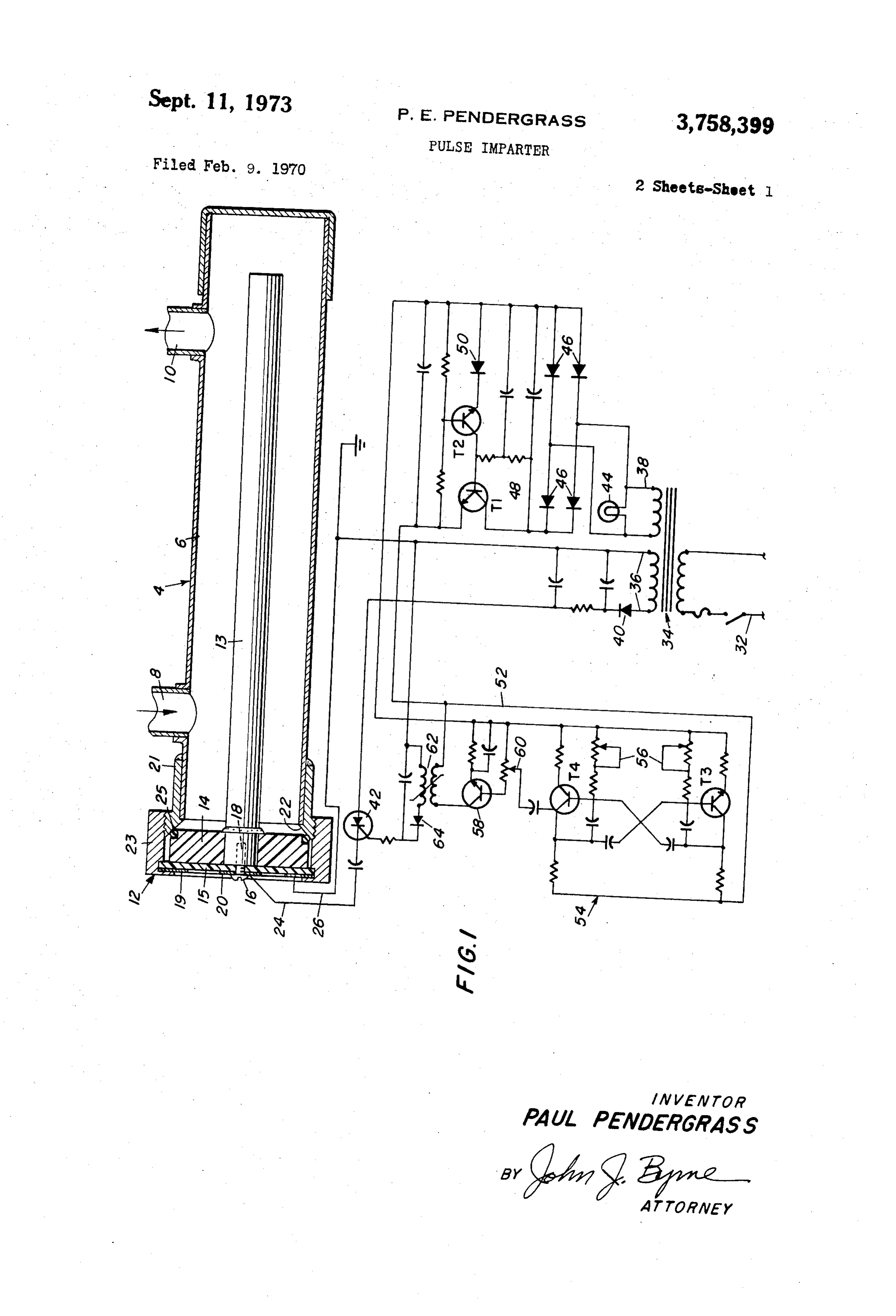
secondary windings of the transformer 34. The circuit 36 3,758,399 leads through a rectifying diode 40 and a silicon controlled PULSE IMPARTER rectifier 42 to the electrode conductor 24 and returns Paul E. Pendergrass, Billings, Mont, assignor to through the return conductor 26. The circuit 38 includes Tri-Tron International, Billings, Mont. a pilot light 44, a rectifier composed of rectifying diodes Filed Feb. 9, 1970, Ser. No. 9,743 46 and a regulator 48 made up of transistors T1 and T2 nt. Cl. B01k 3/00; C22d I/02 and a Zener diode 50. The above components made up
by the described circuitry are known in the art and the particular circuitry is a matter of choice as is well known
ABSTRACT OF THE DISCLOSURE O to the designer skilled in the art, so long as a direct cur An apparatus for imparting an electrical pulse to a rent signal of controlled voltage level is provided. flowing stream of water having an inlet and outlet, a A conductor 52 connects the voltage regulator 48 to a cathode within said housing in the path of said stream free-running multi-vibrator 54 which, through transistors and an electric pulse generating means connected to said T3 and T4, provides a square wave signal, the frequency 5 and/or shape of which is controlled by mechanically inter cathode.
connected variable resistors 56. The signal from the
An objective of this invention is to impart a series of multi-vibrator is transmitted to an amplifier 58 where the electric pulses to a chamber in which a fluid is disposed. conductive level is controlled by variable resistor 60. The More specifically, this invention provides means for im 20 output from the amplifier 58 transmitted to a pulse trans former which transmits a spike pulse through a diode 64 parting said pulses to a moving stream of water. to the silicon controlled rectifier 42 for transmission to Another objective of this invention is to provide an im the electrode 16through the conductor 24. proved cathode assembly with sealing means for sealing In operation, the pulse rate and intensity excitation is the water chamber and having different means for carry determined and set into the circuitry through the proper ing the pulse to the cathode within the chamber. adjustment of the control for the multi-vibrator 54 and the These and other objects of the invention will become 25 conductive level adjustment for the amplifier 58. A fluid more obvious to tose skilled in the art by reference to is circulated through the inlet 8 in the tank 6 and the elec the following detailed description when viewed in light trode is energized so that electrostatic pulses of the de of the accompanying drawings wherein like components sired rate and amplitude is imported to the fluid between thereof are indicated by like numerals throughout the fig 30 the anode 13 and the wall of tank 6. ures and wherein:
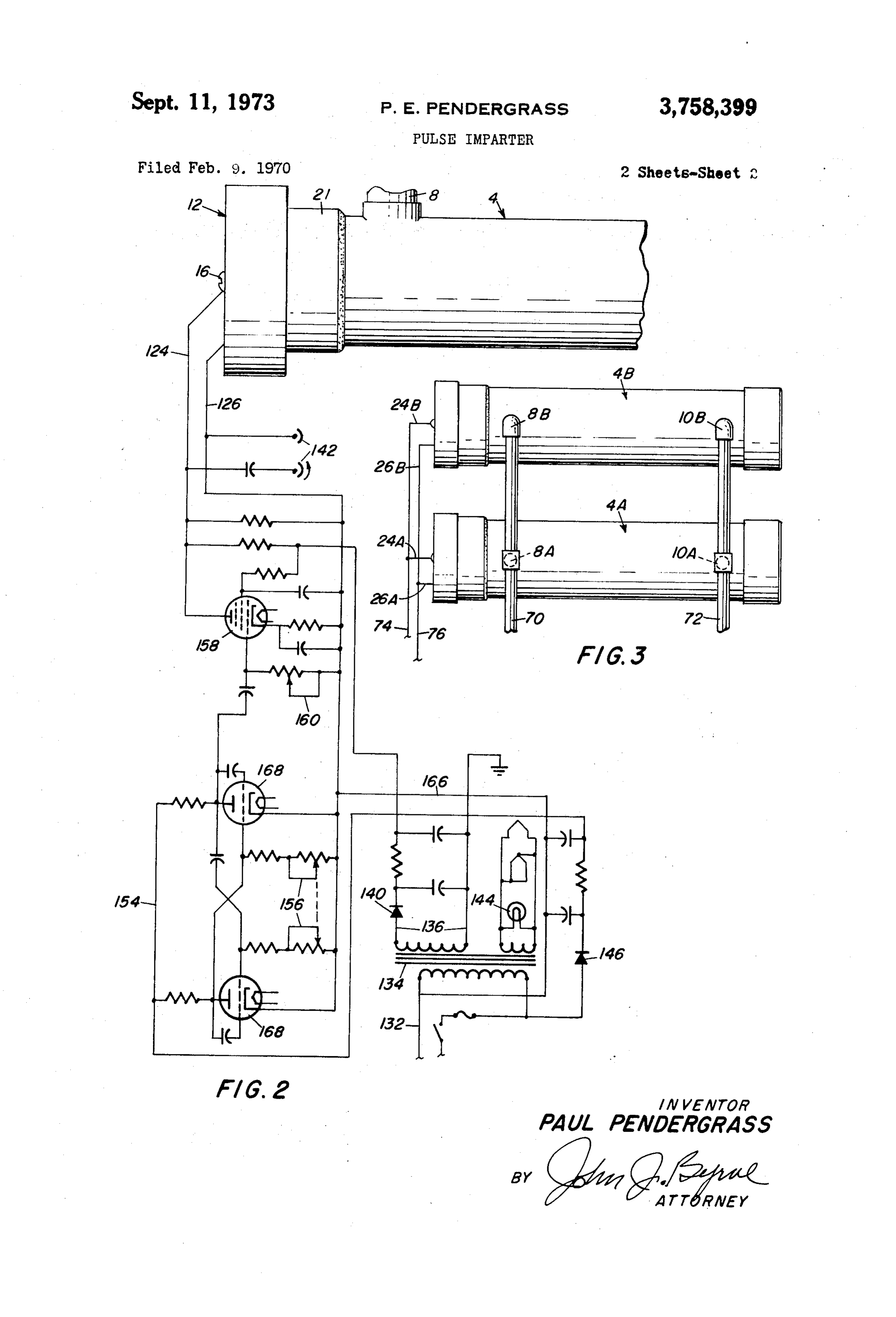
FIG. 1 is a sectional elevational view of an apparatus Turning now to FIG. 2 of the drawings, a vacuum tube in accordance with the invention, together with pulse gen equivalent of the circuit of FIG. 1 is illustrated. In this erating circuitry. figure, components corresponding to like components of FIG. 2 is a variation in the electrical circuitry of the 35 the preceding figure are indicated by like numerals only of the next higher order. In this figure, the apparatus 104 device of FIG. 1; and is connected to an electrode conductor 124 and a return FIG. 3 illustrates a parallel "ganged' arrangement of devices in accordance with the invention. conductor 126 which are, in turn, connected to pulse rate In FIG. 1, a water treating apparatus, in accordance and wave shape forming circuitry which circuitry con with the invention shown generally as 4, is composed of 40 sists in most aspects of a vacuum tube equivalent of the a cylindrical tank 6 having an inlet 8 at one end thereof transistorized circuit shown in FIG. 1. In this figure, power and an outlet 10 the other end thereof. mains 132 are connected to a transformer 134 through a An electrode conductor 24 is connected to the anode switch and current limiting device. A first secondary coil 13 through the ring 20. One end of tank 6 is enclosed by in the transformer 134 is connected to a rectifying circuit 136 which, through a diode rectifier 140 is connected to a cap 11. The other end of tank 6 is enclosed by a closure 45 the assembly 12. The assembly 12 supports an elongated electrode conductor 124. A circuit 166, bypassing the anode 13 within and in spored relationship to the tank 6. transformer 134, is connected on one side, to the return One end of the anode 13 is affixed to a non-conducting conductor 126 and on the other side, to a free-running plastic disc 14. A second plastic disc 15 is secured to disc multi-vibrator 154. The free-running multi-vibrator 154 comprises a pair of triodes 168, the cathodes of which are 14 by way of a screw 16. Disc 15 is apertured at 17 and 50 connected the end of anode 13 is threadably bored at 18 to receive to the circuit 166 and the plates of which are the screw 16. An annular ring 9, of copper or other con connected to the return side of the circuit 166 through a rectifying diode 146. Interconnected variable resistors 156 ducting material, is secured about the outer periphery of control disc 15. A smaller ring 20, of copper or other conducting the bias on the grid of the triodes 168 so that the material, is disposed on disc 15 inwardly of the ring 19. 55 frequencies
of the square wave pulse emitted from the 154 are regulated in a manner well known
The ring 19 is also apertured to receive the screw 16. to those skilled in the art. The output from the multi The assembly 12 further includes a brass retainer sleeve vibrator 154 is transmitted to a pentode amplifier 158 the 21 having an inwardly directed flange 22 adapted to abut conductive level thereof being controlled by a variable the end of tank 6. The outer surface of sleeve 21 is threaded to receive threaded collar 23. The collar 23 is 60 resistor 160. The output from the amplifier 158 is trans formed with an inwardly directed flange 24 which abuts mitted to the electrode and return conduits 124 and 126, conducting ring 19. respectively. The wave form of the output is altered be Adjacent the flange 22, the interior surface of sleeve 21 tween by the discharge device 142 to provide a spiked is formed ith a frusto-conical surface 24. An O-ring 25 pulse signal when desired.
can be disposed between the disc 14 and the conical sur 65 atesTheinvacuum tube circuitry, as shown in FIG. 2, oper face 24 to aid in sealing tank 6, and a return current con circuitry of FIG. 1similar a manner to that of the transistorized for the same purposes. By control ductor 26 is connected to the wall of the tank 6 through of the free-running multi-vibrator 154 and the conduc ring 19.
The electrical circuitry for the embodiment of FIG. 1 tive level of the amplifier 158, the pulse rate and the wave is designated by a power main 32 controlled by a switch 70 shape imparted to fluid in the tank 104 can be adjusted. and a current limiting device feeding into a transformer In FIG. 3, apparatus for utilizing the device of this 34. A pair of rectifying circuits 36 and 38 lead from the invention in multiple or bank form is shown. In this figure,
Page 4
a pair of tanks are connected in parallel through an inlet a first conducting ring electrically connected to said conduit 70 connected to the inlets 8A and 8B of the tanks source and mounted on said disc, shown and an outlet conduit 72 connects the outlets 10A a second conducting ring on said disc electrically con and 10B of the tanks shown. The electrode conduits 24A nected to ground potential, and 24B and the return conduits 26A and 26B are con third means powered by a controlled source of direct nected to buses 74 and 76 as shown. A plurality of tanks current energy to vary the frequency and intensity can be arranged in this manner to impart a succession of said pulse including in series, of pulses to traveling fluid. a free-running multivibrator having a circuit means What has been set forth above is intended as exemplary for adjusting the frequency thereof, of teachings in accordance with the invention to enable an input adjustment means for varying the am those skilled in the art in the practice thereof. It should, O plitude of the output of said free-running multi therefore, be understood that, within the scope of the vibrator, appended claims, the invention may be practiced other an output transistor amplifier connected to the than as specifically described. input adjustment means, and What is novel and therefore desired to be protected by 5 an output pulse generator connected to the output Letters Patent of the United States is: of said transistor amplifier for providing said 1. An apparatus for imparting an electrical pulse to a electrostatic pulse to the fluid in said container. moving fluid comprising, 2. The apparatus in accordance with claim 1 wherein a cylindrical container having an inlet and an outlet, a plurality of containers are connected in parallel with an elongated tubular element member extending into 20 said first-mentioned container.
said container and defining an annular space there with, References Cited first means for circulating a fluid from said inlet UNITED STATES PATENTS through said annular space and departing through 3,528,905 9/1970 Miller --------- 204-275 X said outlet, 25 3,402,120 9/1968 Allen et al. ------- 204-149 X a plastic disc means affixed to one end of said electrode, · 3,480,529 11/1969 Waltrip ---------- 204-149 ? second means engaging the periphery of said disc means 3,625,884 12/1971 Waltrip ---------- 204-149 X and supporting said electrode member in spaced, 3,637,482 1/1972 Vajda -------------- 204-228 insulated relation along the axis of said cylindrical container, 30 JOHN H. MACK, Primary Examiner a source of low frequency, pulsating electrical energy D. R. VALENTINE, Assistant Examiner connected to said electrical and said container for imparting a low frequency electrostatic pulse to a U.S. Cl. X.R. fluid in said container, 204-275, 305
Provenance
- Collection
- Cited prior art
- Original PDF
- patentimages.storage.googleapis.com →
- Filed
- 1970-02-09
- Pages
- 4
- Method
- pdftotext (the PDF's own text layer) + pdftoppm 300dpi page scans
- Source
- Google Patents bibliographic record
- Granted
- 1973-09-11
- Inventors
- P Pendergrass; Tri-Tron International
- Transcribed from
- patentimages.storage.googleapis.com →