patent · US2988000
Pumping apparatus
13 June 1961
Page 1
Drawing sheet — no readable text.
Page 2
Drawing sheet — no readable text.
Page 3
United States Patent Office 2,988,000 Patented June 13, 1961
outwardly of at least one end of the duct and comprising 2,988,000 a plurality of coil-formed (that is, spiral or helical) con PUM.PNG APPARATUS ductors each connected to an electrode at said end of the Leslie Reginald Blake, Rugby, England, assignor to The duct, said conductors being mutually isolated electrically British Thomson-Houston Company Limited, London, except at the duct. This pump may be termed a spiral England, a British company conduction pump by analogy with the aforementioned Filed Oct. 4, 1957, Ser. No. 688,188 spiral induction pump, although in fact the duct is again Claims priority, application Great Britain Oct. 5, 1956 5 Claims. (C. 103-1) helical rather than spiral in form.
In carrying out the invention similar composite windings
This invention relates to so-called electromagnetic O surrounding the core are preferably provided outwardly pumps in which an electrically conductive liquid, such, for of both ends of the duct with their coil-formed conductors example, as a liquid metal, is propelled along a duct by a connected to the end electrodes provided for the duct at force generated by the reaction between a transverse mag the opposite ends thereof, the sense of these windings be netic field and an electric current passed through the ing such that each aids the other in the production of flux liquid transversely both of the duct and of said field, the 5 across the duct between the pole and the core. The con action being somewhat analogous to that of an electric ductors constituting the or each winding are preferably motor. spiral in form, being then coiled one within another, and The well known, A.C. excited, flat linear induction may with advantage be respectively connected to individ pumps and annular linear induction pumps are more suit ual electrodes spaced round the duct axis and connected ed to the pumping of liquid metals having properties such 20 to the end turn of the duct at the relevant end. as those of liquid sodium than to the pumping of liquid In operation, current applied at the free ends of the metals such as mercury or liquid bismuth having rela coil-formed conductors of the or each composite wind tively high values of density, viscosity and resistivity. On ing flows through the winding or windings and also along the other hand the spiral (or, more strictly, helical) type the duct between the electrodes at its opposite ends. In of induction electromagnetic pump, also A.C. excited and 25 other words the pump is self-excited. Assuming that functioning to urge the metal being pumped along a heli alternating current is employed, the fact that the com cal duct under the influence of a radial magnetic field ro ponent conductors of the or each winding are mutually tating about the axis of the helix and reacting with cur isolated electrically except at the duct, the conductors rent induced thereby in the liquid, tends to have a poor to this end being fed from effectively separate sources power factor and to be somewhat inefficient with liquids 30 of current such as separate secondary windings on a supply such as mercury. This inefficiency is especially disad transformer, results in eddy current losses in the con vantageous where the amount of heat generated in the ductors being reduced to a minimum.
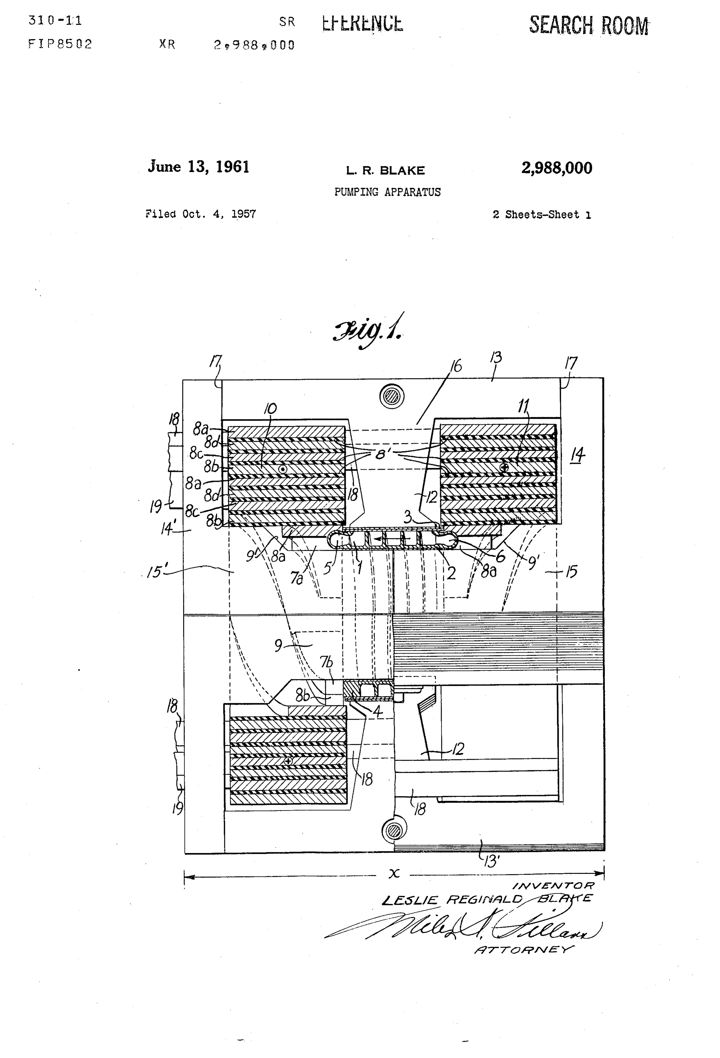
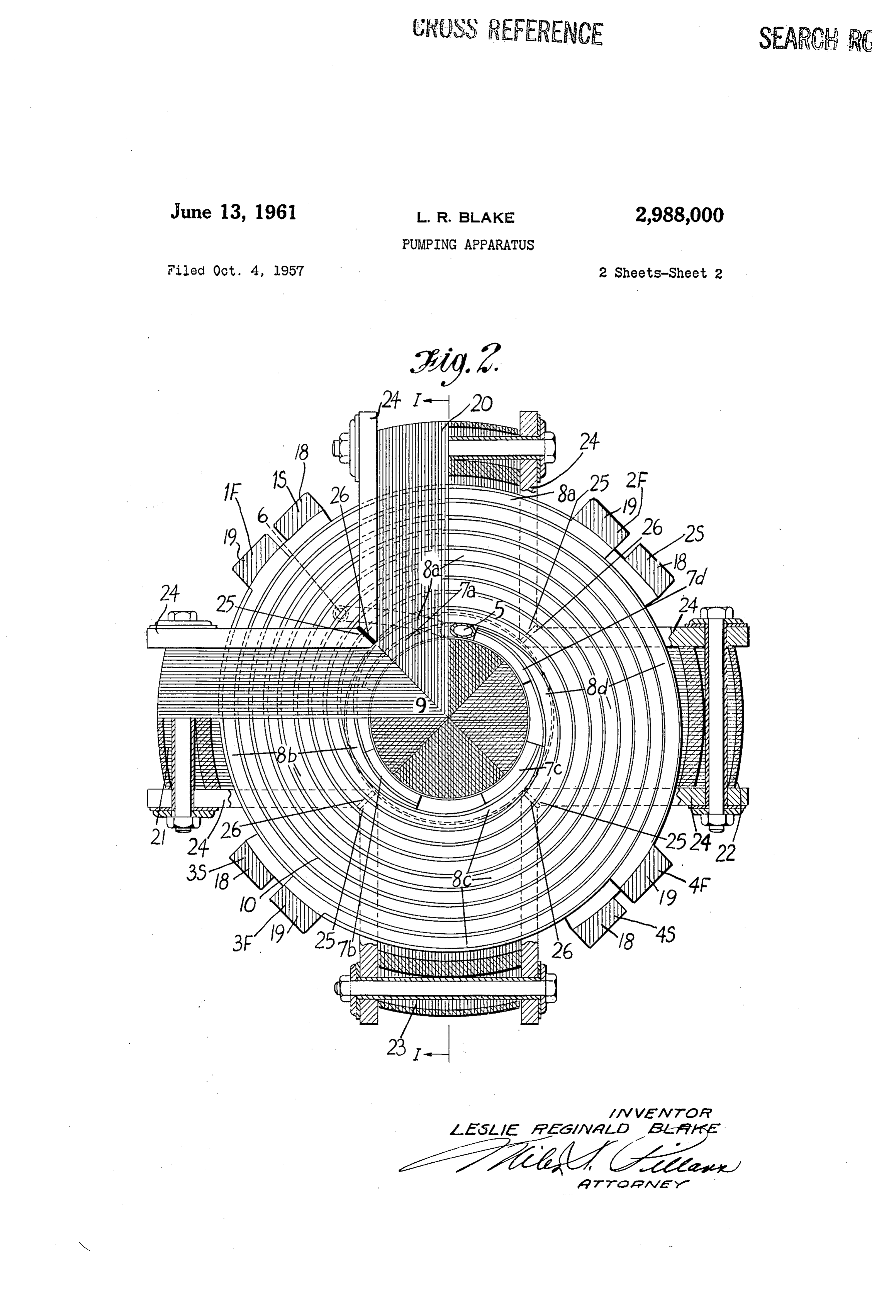
liquid due to electrical losses must be reduced to a mini For A.C. operation the magnetic structure would of mum, as when the pump is likely to be frequently oper course be laminated or otherwise suitably constituted in ated under standstill conditions with the full output pres accordance with usual practice in order to minimize eddy sure developed so that the heat generated cannot be car current losses therein. To this end the magnetic struc ried away by the liquid. It is also a matter of some diffi ture may be made up of angularly disposed packs of culty, where a spiral induction pump is to be used for laminations in which the laminations lie generally parallel pumping conductive liquid that is radioactive or at a high to the duct axis, each pack defining a segmental part of temperature, to obtain a reliable pump having a winding 40 the core and annular pole and also a corresponding part that will withstand these conditions. Moreover if the of the yoke. Each pack may then be itself made up winding is heat insulated from the liquid, the pump be of two or more sections including one which defines the comes of even lower efficiency and power factor. Also, relevant as the pipe duct may then not be supported externally by relation toparttheofother the annular pole and is so formed in section or sections that when being material of intrinsically high strength, it is difficult to make assembled therewith it is free for some radial movement the pipe duct capable of withstanding high pressure, as it with may have to do in certain applications. Conventional of therespect thereto whereby the pole-defining sections A.C. or D.C. conduction pumps, in which current through the outside oflamination several packs can clamp firmly round the liquid being pumped is applied externally rather than against internal pressure andduct, the helical thereby to support it thus enhance the suitability induced, could satisfy at least some of the requirements 50 of the pump for use at high pressures. indicated, but with such pumps it is difficult to develop a In order that the invention may be more fully under high ratio of output pressure to rate of liquid flow without stood reference will now be made to the accompanying substantial sacrifice in respect of efficiency or size or both. drawings which illustrate a pump embodying the inven It is therefore an object of the present invention to pro tion and in which, in particular, vide a novel form of conduction pump which is especially 55 suitable for operation with A.C. excitation and can readily FIG. 1 is a side elevation of the pump taken in axial be designed to give a relatively large ratio of output pres cross-section except for the lower right-hand quarter of sure to rate of flow with liquids such as mercury and bis the figure which is in full side elevation, and muth and can also be designed to meet other require FIG. 2 is an end elevation of the pump taken in trans ments such as reliability, good efficiency and power factor 60 verse cross-section except for the upper left-hand quadrant and ability to withstand high pressure. which is in full end elevation. According to the invention there is provided an electro Considering the general construction of the illustrated magnetic pump of the conduction type comprising in pump before referring in detail to the drawings, the pump combination: a helical duct having conductive connection comprises a helical duct defined in effect between the between its successive turns; a magnetic structure defin 65 inner and outer walls of a double-wall hollow cylinder. ing an annular pole coaxially surrounding said duct, a An inlet pipe is joined to the duct at one end of this central core surrounded by the duct, and a yoke portion cylinder, and an outlet pipe at the other end. Also at interconnecting the pole and core; and electrodes for the each end of this cylinder are a number of segmental elec duct disposed at opposite ends thereof to permit applica trodes, preferably of a high conductivity material such as tion of current through the duct lengthwise of its axis and 70 copper, which are cast, welded, brazed or otherwise se thus transversely of the successive turns of the duct; and cured to the end walls of the duct. To each of the a composite exciting winding surrounding said core axially electrodes is attached one end of a strip conductor, as
Page 4
of copper, which is wound into a spiral to form a com as 15 and 15, for the central core section 9 and the re posite magnetizing winding in conjunction with the other, spective yoke portions, such as 14 and 4, and a part 16 similarly formed, strip conductors at the same end, all for the pole 12 and yoke portion, such as 13 and 13. Butt the strips at the same end being interleaved with each joints 17 formed in transverse planes between the parts other and being mutually isolated electrically with inter 15 and 16 permit the parts 16 to be firmly clamped about vening insulation except where they are connected by Way the duct cylinder 2-3 to support the latter against internal of the electrodes and the end walls of the duct. The pressure. The lamination packs 20–23 are shown clamped windings thus formed at each end are wound in a similar together by clamps 24 which again may be of copper or hand so that current flowing from the radially outer ends may be of stainless steel if cooling requirements are less of the strips in one winding towards the electrodes, at theirO arduous.
radially inner ends and passing from there along the duct, The clamps 24 for each pack inter-fit with those of the will flow outwardly from the radially inner ends of adjacent packs, being to this end chamfered at 25 as indi the strips of the other winding to their outer ends. Emi cated, and pieces of electrical insulation 26 are inserted bracing the two composite magnetizing windings is a lami between the clamps 24 to reduce any tendency to produce nated magnetic structure defining a core within the duct 5 a shorted turn effect. The widths of the spirally wound cylinder and an annular pole round the outside of this strip conductors 8a-d are tapered at their inner ends to cylinder. The strips of one winding are respectively con accommodate the change at 9 in the section of the central nected to corresponding ends of separate secondary wind core 9 and are also cut away in parts to allow for the ings on a Supply transformer, while the strips of the other pipes 5 and 6 to be led to and from the pump duct. winding are respectively connected to the remaining ends 20 The outer end of each spiral strip 8a-d in the winding of the secondary windings; that is, the strips of one wind 11 at one end of the pump has joined to it a conductive ing are connected to the "starts' of the respective trans bar 18 which extends axially to the other end of the pump former secondary windings and the strips of the other Where it is connected to the supply transformer (not winding to the "finishes' of these windings. As a result, shown). The outer end of each spiral conductor 8a-d When the transformer is energized current will flow 25 of the winding 10 at this other end of the pump has like through the exciting windings to establish a field across wise joined to it a conductive bar 19 connected at this the duct between the pole and the core, and this field will same end to the transformer. The bars 18 are connected react with the same current where it flows in the duct, to corresponding ends of four separate secondary windings to drive the liquid along and around the helix. on the Supply transformer, and the bars 19 are connected Turning now to the figures in detail, the helical pump 30 to the other ends of these windings. These connections duct 1 is shown constructed in two parts, namely an inner are indicated in FIG. 2 by the notations 1S,2S,3S and 4S part 2 which is machined with helical grooves to define applied to the conductors 18 and 1F, 2F, 3F and 4F ap three sides of successive turns of the duct and an outer plied to the conductors 19, the letters S and F denoting part 3 which is fitted over the inner part 2 and welded to connection to "starts” and "finishes' respectively of the it to complete the helical duct 1, the latter being therefore 35 transformer secondary windings and the appended nu effectively defined between inner and outer walls of a merals indicating to which particular one of the four wind double-walled cylinder 2-3. A conductive connection is ings the connection is taken. For maximum electrical afforded between the successive turns of the duct through efficiency, the supply transformer is preferably located the duct walls, as defined between the grooves machined close to the pump at the end to which the bars 18 extend. in the part 2. The end walls 4 are thickened for strength 40 Preferably also, the primary and secondary windings of and at Suitable points round the periphery an inlet tube 5 the transformer would be interleaved to minimize the leak is welded at one end and an outlet tube 6 at the other. age reactance of the transformer. The transformer pri Also spaced around each end of the duct are four seg mary can be Supplied from an alternating voltage having mental electrodes 7a-d, as of copper, which are cast in an amplitude according to the number of turns on the pri tegral with or welded to the end walls 4. These electrodes mary and secondary windings and some suitable frequency 7 are machined so that respective copper strip conductors which, for the pump shown, is preferably 15 c./s. in order 8a-d can readily be attached to them as by brazing. The to obtain the best power factor without making the trans four conductors 8a-d attached to the electrodes at each former too large. Normal supply frequency, that is 60 end are Wound spirally together to form a composite mag c./S., may also be suitable however.
netizing winding 10 at one end and 11 at the other end, 50 With a pump of the form described having the dimen each conductor being electrically isolated from its neigh sion x of about 3.75 inches and the other dimensions to bour, except where it is connected through its electrode 7 Scale, standstill pressure in excess of 100 lb./sq. in. can be to the end wall 4, to avoid making a shorted turn. This realized without overheating the winding and a flow of electrical isolation of the conductors 8 is ensured by inter nearly 1 gal/min, can be achieved but at a somewhat lower pressure.
vening insulation 8 and by connecting them, as will be further described later, to separate secondary windings A pump, constructed as hereinbefore described and of a supply transformer (not shown) providing excitation illustrated has a number of advantages. Since it is A.C. for the magnetizing windings. The electrical insulation excited, a Supply transformer can be located close to the can be mica or any other high temperature insulation of pump to increase the voltage to a higher level so that the low or high grade. The spiral windings 10 and 11 are 60 actual supply can be located distant from the pump with wound in respective senses, such that the current flow in negligible bus bar losses. The transformer, being static them is in opposite directions; for example, the current equipment, should be highly reliable and need no main in 10 is shown as being clockwise and in 11 anti-clockwise. tenance, and so also should the pump since it is of robust The magnetic circuit of the pump includes a central mag construction and requires electrical insulation of only a netic laminated core 9 which the helical duct 1 surrounds, Very low level of the order for instance of one volt. The the cross-section of this core being increased, as indicated Windings 10 and 11 are shown as having about 24 effec at 9', at positions outwardly of the ends of the channel. tive turns each but a higher or lower number of turns The remainder of the magnetic circuit, also laminated, could be employed. With a smaller number of magnetiz consists of an annular pole 12, surrounding the duct 1 and ing turns the Supply current would be larger and the volt preferably shaped in the manner shown to keep leakage 70 age lower; also there would be greater armature reaction flux to a minimum, and yoke portions, such as 13 and 13, effects, which may make it necessary to have a compen together with further yoke portions, such as 14 and 14. Sating winding, and the ohmic loss in the liquid would The magnetic structure is shown made up of four lami be higher, but to compensate the power factor would also nation packs 20–23 at right angles to each other, and each be higher. With a larger number of turns the current stack is made up of three parts, namely two parts, such 75 Would be lower, the voltage higher, the power factor
Page 5
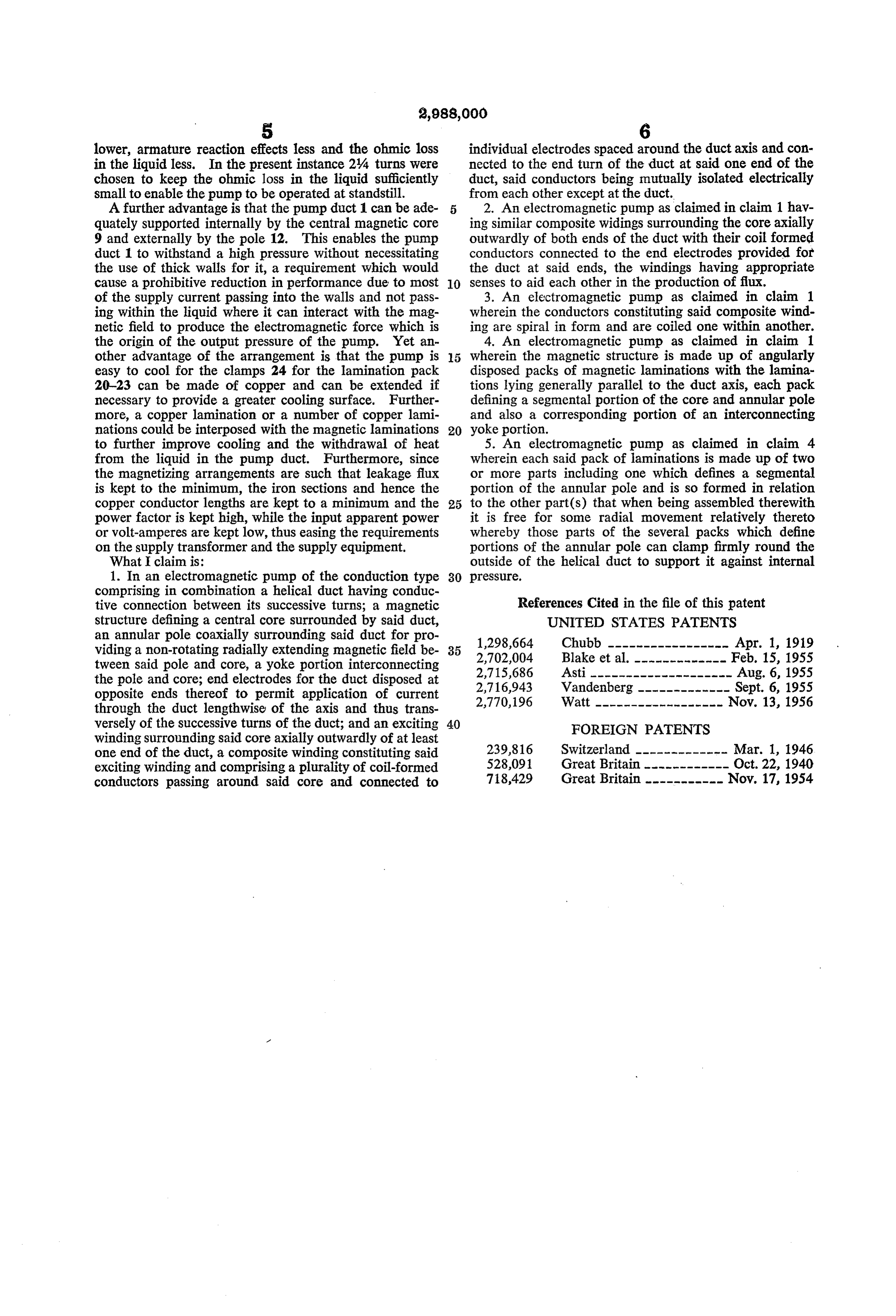
lower, armature reaction effects less and the ohmic loss individual electrodes spaced around the duct axis and con in the liquid less. In the present instance 24 turns were nected to the end turn of the duct at said one end of the chosen to keep the ohmic loss in the liquid sufficiently duct, said conductors being mutually isolated electrically small to enable the pump to be operated at standstill. from each other except at the duct. A further advantage is that the pump duct 1 can be ade 2. An electromagnetic pump as claimed in claim 1 hav quately supported internally by the central magnetic core ing similar composite widings surrounding the core axially 9 and externally by the pole 12. This enables the pump outwardly of both ends of the duct with their coil formed duct 1 to withstand a high pressure without necessitating conductors connected to the end electrodes provided for the use of thick walls for it, a requirement which would the duct at said ends, the windings having appropriate cause a prohibitive reduction in performance due to most O senses to aid each other in the production of flux. of the supply current passing into the walls and not pass 3. An electromagnetic pump as claimed in claim 1 ing within the liquid where it can interact with the mag wherein the conductors constituting said composite wind netic field to produce the electromagnetic force which is ing are spiral in form and are coiled one within another. the origin of the output pressure of the pump. Yet an 4. An electromagnetic pump as claimed in claim 1 other advantage of the arrangement is that the pump is 5 wherein the magnetic structure is made up of angularly easy to cool for the clamps 24 for the lamination pack disposed packs of magnetic laminations with the lamina 20-23 can be made of copper and can be extended if tions lying generally parallel to the duct axis, each pack necessary to provide a greater cooling surface. Further defining a segmental portion of the core and annular pole more, a copper lamination or a number of copper lami and also a corresponding portion of an interconnecting nations could be interposed with the magnetic laminations 20 yoke portion.
to further improve cooling and the withdrawal of heat 5. An electromagnetic pump as claimed in claim 4 from the liquid in the pump duct. Furthermore, since wherein each said pack of laminations is made up of two the magnetizing arrangements are such that leakage flux or more parts including one which defines a segmental is kept to the minimum, the iron sections and hence the portion of the annular pole and is so formed in relation copper conductor lengths are kept to a minimum and the 25 to the other part(s) that when being assembled therewith power factor is kept high, while the input apparent power it is free for some radial movement relatively thereto or volt-amperes are kept low, thus easing the requirements whereby those parts of the several packs which define on the supply transformer and the supply equipment. portions of the annular pole can clamp firmly round the What claim is: outside of the helical duct to support it against internal 1. In an electromagnetic pump of the conduction type 30 pressure.
comprising in combination a helical duct having conduc tive connection between its successive turns; a magnetic References Cited in the file of this patent structure defining a central core surrounded by said duct, UNITED STATES PATENTS an annular pole coaxially surrounding said duct for pro 1,298,664 Chubb ----------------- Apr. 1, 1919 viding a non-rotating radially extending magnetic field be 35 2,702,004 Blake et al. ------------- Feb. 15, 1955 tween said pole and core, a yoke portion interconnecting 2,715,686 Asti -------------------- Aug. 6, 1955 the pole and core; end electrodes for the duct disposed at 2,716,943 Vandenberg ------------- Sept. 6, 1955 opposite ends thereof to permit application of current 2,770,196 Watt ------------------ Nov. 13, 1956 through the duct lengthwise of the axis and thus trans versely of the successive turns of the duct; and an exciting 40 FOREIGN PATENTS winding surrounding said core axially outwardly of at least one end of the duct, a composite winding constituting said 239,816 Switzerland ------------- Mar. 1, 1946 exciting winding and comprising a plurality of coil-formed 528,091 Great Britain ------------ Oct. 22, 1940 conductors passing around said core and connected to 718,429 Great Britain ----------- Nov. 17, 1954
Provenance
- Collection
- Cited prior art
- Original PDF
- patentimages.storage.googleapis.com →
- Filed
- 1957-10-04
- Pages
- 5
- Method
- pdftotext (the PDF's own text layer) + pdftoppm 300dpi page scans
- Source
- Google Patents bibliographic record
- Granted
- 1961-06-13
- Inventors
- Blake Leslie Reginald; British Thomson Houston Co Ltd
- Transcribed from
- patentimages.storage.googleapis.com →