patent · US4213433
Liquid fuel to gas converter for engines
22 July 1980
Page 1 — bibliographic record
United States Patent (19) (11) 4,213,433 Day . (45) Jul. 22, 1980
(54) LIQUID FUEL TO GAS CONVERTER FOR 1,319,718 10/1919 Martin .............................. 123/122 F ENGINES 1,325,998 12/1919 Schmid et al. ................... 123/122 F 1,326,000 12/1919 Schmid ............................. 123/122 F (76) Inventor: John C. Day, 2316 Stafford La., 2,821,843
Mesquite, Tex. 75150 3,986,486 10/1976 Rabbiosi........................... 123/122 E (21) Appl. No.: 846,774 Primary Examiner-Ronald H. Lazarus 22) Filed: Oct. 31, 1977 Attorney, Agent, or Firm-Warren H. Kintzinger (51) Int. C.’............................................. FO2M 31/00 57 ABSTRACT (52) U.S. C. .................................... 123/549; 123/555; A liquid fuel to gas converter and feed structure for
(58) Field of Search ............... 123/122 E, 133, 122 F, internal combustion engines. Liquid fuel is transformed 123/122 D, 122 H, 122 C; 261/144, 145, 142 to the molecular gaseous state after being meter fed References Cited while it is passed through an elongate heated tubular 56) element from which it is mixed with air being fed to the
1,107,967 8/1914 Knaak .............................. 123/122 C 1,311,532 7/1919 Schmid ............................. 123/122 F 12 Claims, 6 Drawing Figures
area areas a yeaeveyaa
AAAAAyAyAVA
SZZZZZZ ZZZZ
a YaYa
F S. ZZZZZZZZZZZZ
AAAAAAAAAAAR
Page 2
Drawing sheet — no readable text.
Page 3
Drawing sheet — no readable text.
Page 4
Drawing sheet — no readable text.
Page 5
energy increasing as the temperature increases. Volume
LIQUID FUEL TO GAS CONVERTER FOR of a given mass of gaseous state fuel is dependent upon ENGINES the temperature and pressure it is under at any particu lar time with three variables in the state equation tem
This invention relates in general to liquid fuel gassifi perature, pressure and volume, cation for improved fuel economy and internal combus When liquid or vapor mist react, no common general tion engine performance and, in particular, to an engine ization fuel gassifier having an elongate heated tubular element tants andcanproducts be made concerning the volumes of reac such as applicable to fuel in the gase into which liquid fuel is metered and from which fuel in ous molecular state and gaseous state air required for the gassified form is passed and mixed with intake air to 10 combustion. However, when substances in the gaseous an engine.
Fuel economy is important with vehicles today, par state are involved in chemical change, a definite volume ticularly, with present energy problems including fuel products. Theexists relationship among the gaseous reactants and relationship allows for optimized fuel-air shortages and constantly increasing fuel costs. Environ mixture by simple volumetric relationships and supports mental pollution problems have resulted in legislative 15 desired combustion characteristics. action requiring more efficient engines with less pollu ploying carburetors of a preexistingWith engines em tion to meet tighter emission standards. Exhaust gas ture, intake air breaks fuel into fine droplets and therenais conventional recirculation, catalytic converters and/or auxiliary air some gassification. However, since droplet size varies pumps and other controls are being designed into vehi with cles greatly increasing vehicle costs so, obviously, if 20 wide intake air speed and intake air speed varies over a engine fuel economy efficiency is increased such that higherrange, droplet size varies from smaller droplets at pollution control equipment is not needed, further en take air speeds.air speeds to larger droplets at lower in intake gine efficiency increase is attained. With the improved fuel feed system after fuel gasifi Most present day internal combustion engines use liquid gasolines as fuel that is a product of expensive 25 cation the molecular gaseous state fuel is mixed with air petroleum cracking and reforming processes of an in in controlled volumetric range portions for desired volved nature. Such extensive reforming processes, and engine performance and efficiency of operation. More inclusion of fuel additives is important in attaining correctly exact fuel to air mixtures for combustion can higher fuel octane ratings required with many present be maintained through out the varied range of engine engines since octane rating, for example, is a factor in 30 power requirements with the mixing accomplished ei determining compression ratio in engine design. The ther through an intake manifold or in a chamber near improved fuel system transforms liquid fuel to the mo the cylinder. Although it is well known that proper fuel lecular gaseous state and in doing so, enables use of a to air mixture provides increased power, preexisting considerable range of hydrocarbon distillates, generally systems have not found a solution utilizing liquid or in a range from 50° C. to 300° C., including those known 35 vapor fuel and air consistently providing reasonably commercially as gasoline and kerosene. With fuel being optimized proper mixture. Generally, present combina converted to the gaseous molecular state prior to usage, tion techniques have been depending on combustion of octane ratings as such become irrelevant with light and liquid or vapor misted fuels in air with such fuels in a heavy hydrocarbons such as methane, ethane, fuel oils state tending to cluster fuel molecules close together and others interchangeably useable. lowering their kinetic energy and decreasing desired Preexisting internal combustion engines rely gener combustion characteristics. Fuels in the liquid and ally on liquid or vapor gasoline as fuel with carburetion misted form also have a high density per unit area, and fuel injection the most common ways of feeding requiring additional fuel to fill the same volume. When fuel to the engine in the liquid or vapor mist state. Gaso both the fuel and air mixture are in a gaseous state, it line in these states reacts quite differently from gaseous 45 provides a uniform mixture, separation of molecules, a state fuel particularly with respect to changes in tem high kinetic energy, total elasticity (no loss in energy perature and pressure. Gaseous state fuels follow the due to collision), and uniform combustion. Additives kinetic molecular theory of matter with gaseous state are added to present day fuels as antioxidant inhibitors, products providing greater freedom of movement of metal deactivators and surface ignition inhibitors. Basi molecules than when in the liquid or vapor mist states, 50 cally these additives are required to improve the octane with movement of the gaseous state molecules limited rating and to inhibit adverse chemical recombination of only by the walls of the containing vessel. Molecules in the fuel in the combustion mixture. These additives a liquid or vapor mist state are clustered close together reduce the combustion capability of the fuel to air mix thus having a relatively small amount of kinetic energy ture causing hazardous by-products and have adverse when compared to the gaseous molecular state mole 55 by-product reactions upon combustion leaving deposits cules having almost unlimited freedom of movement. in the cylinder and creating adverse exhaust fumes. Gaseous state molecules are in constant motion collid Contrarily, the gaseous state combustion process does ing frequently with each other and the walls of the not utilize any of these additives in its fuel to air mixture chamber. Under normally encountered environmental allowing a complete, fume free combustion process. In conditions, the distance between molecules are large 60 the gaseous state, chemical change effects are mini compared to the size of the molecules themselves, with mized such as absorption of oxygen by hydrocarbons, molecules of a gaseous state substance moving in all reaction with metal, and surface ignition due to the directions with an average velocity at a given tempera large separation of the molecules, perfect elasticity, and ture. Further, molecules of a gaseous state substance are chemical stability. The molecular injection combustion perfectly elastic with no energy being lost as a result of 65 process is a high purity gaseous hydrocarbon and air collision of molecules. The temperature of material in technique which expands only on ignition (providing the molecular-gaseous state is directly proportional to faster ignition) leaving no adverse exhaust by-products the average kinetic energy of the molecule with kinetic and increasing the power and life of the engine.
Page 6
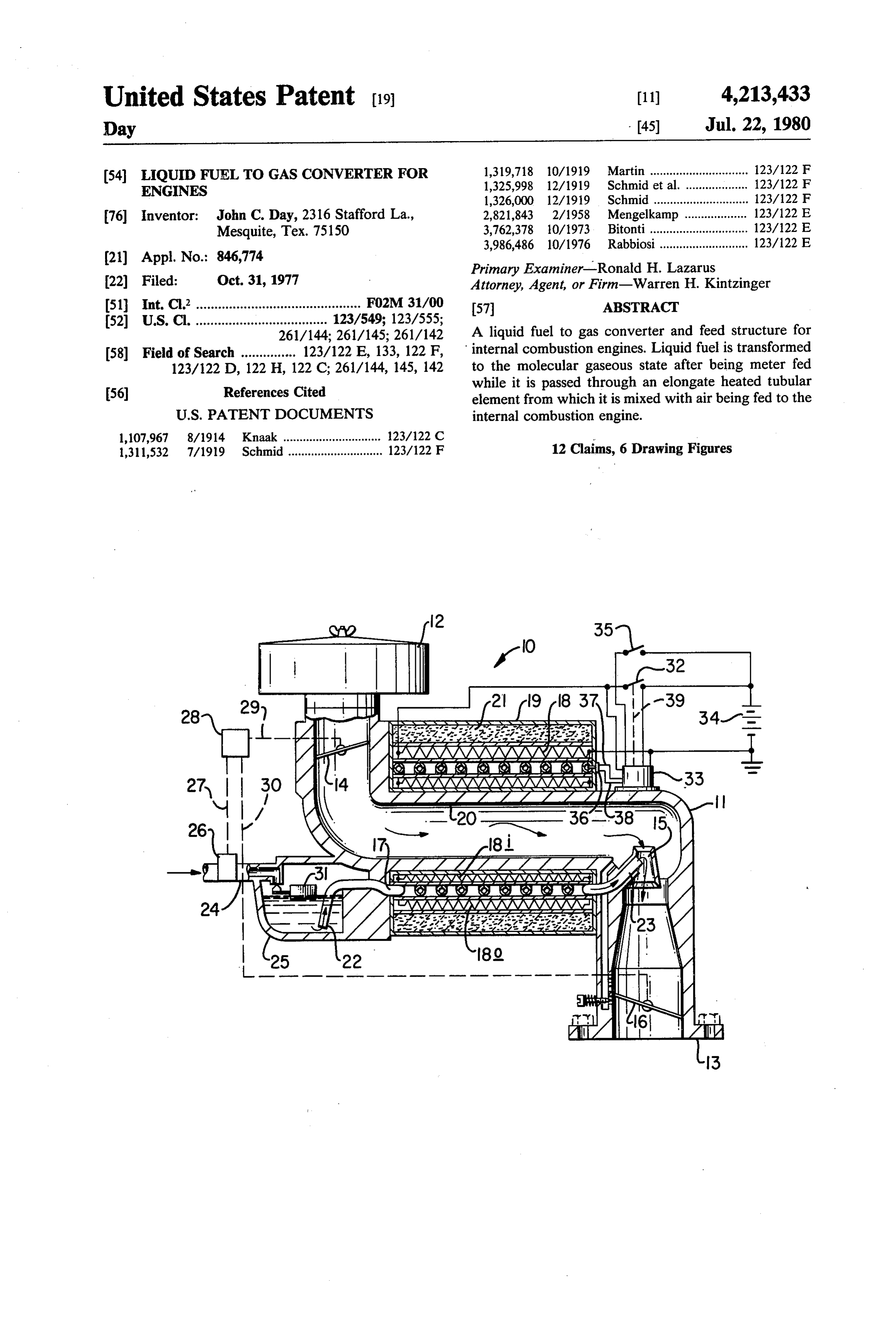
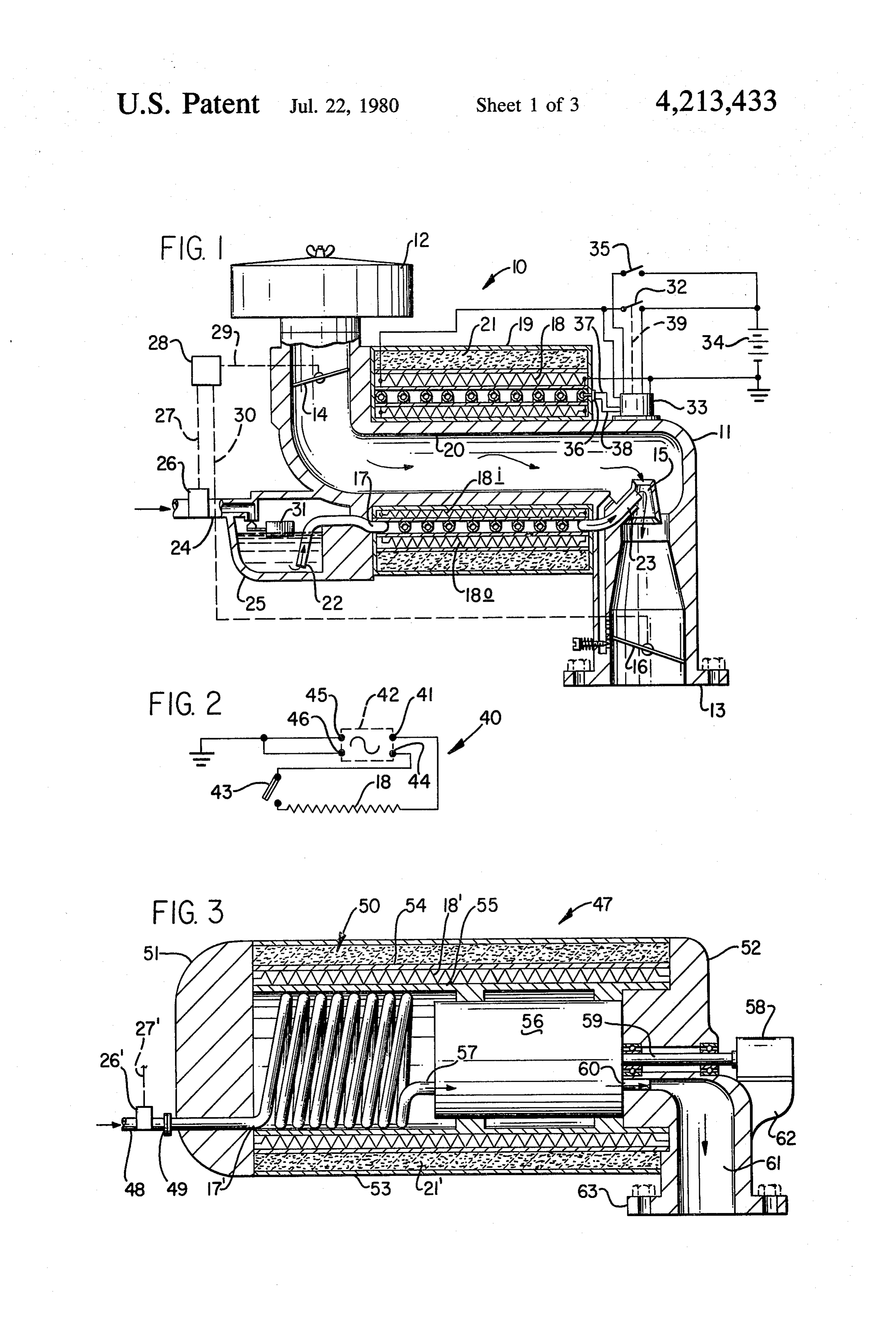
It is therefore a principal object of this invention to line 24, feeding liquid fuel to feed control reservoir 25, provide fluid fuel gassification to the molecular gassi is equipped with a fuel metering needle valve 26, that is fied state for internal combustion engines. subject to control by a mechanical drive linkage con Another object is to increase internal combustion nection 27 with a drive throttle control 28 (of conven engine efficiency that fuel consumption is greatly re age tional type construction detail not shown). Drive link duced. connections 29 and 30 also extend from drive throt A further object with such fuel systems is to reduce tle control to butterfly valves 14 and 16, respectively, in engine emission pollution through improved engine the inlet through air passage structure 11. performance and efficiency. Metered liquid fuel is further flow controlled by float Still another object is to eliminate any requirement 10 valve structure 31 in the reservoir 25 and flows from the for emission pollution control devices through greatly reservoir 25 into the input end 22 of the coiled tube 17. increased internal combustion engine efficiency. Tube 17 is of such material, so sized and of such longitu Features of this invention useful in accomplishing the that,dinal length through the coil convoluted body thereof above objects include an engine liquid fuel gassifier with thermostatically regulated heat input from the heating element 18, it is such as to ensure therein having an elongate heated tubular element into which 15 substantially liquid fuel is metered and from which fuel in the molec complete transformation of liquid fuel to a ular gassified state is passed and mixed with intake air to molecular gaseous state as the fuel is moving there an engine. Fuel metering means and air flow means are through before it reaches outlet end 23. An end of elec provided along with heating and automatic heating tric heating element 18 is connected to ground and the control structure to ensure substantially complete trans 20 other end of element 18 is connected to, and through, formation of fuel from the liquid state to the fully mo both switch 32 and temperature control 33 (of conven lecular gassified state. tional construction detail not shown) in parallel to the Specific embodiments representing what are pres positive side of battery 34 that has a negative side con ently regarded as the best modes of carrying out the 25 isnection to ground. A manually operated start switch 35 closed to supply power to temperature control 33 and invention are illustrated in the accompanying drawings.
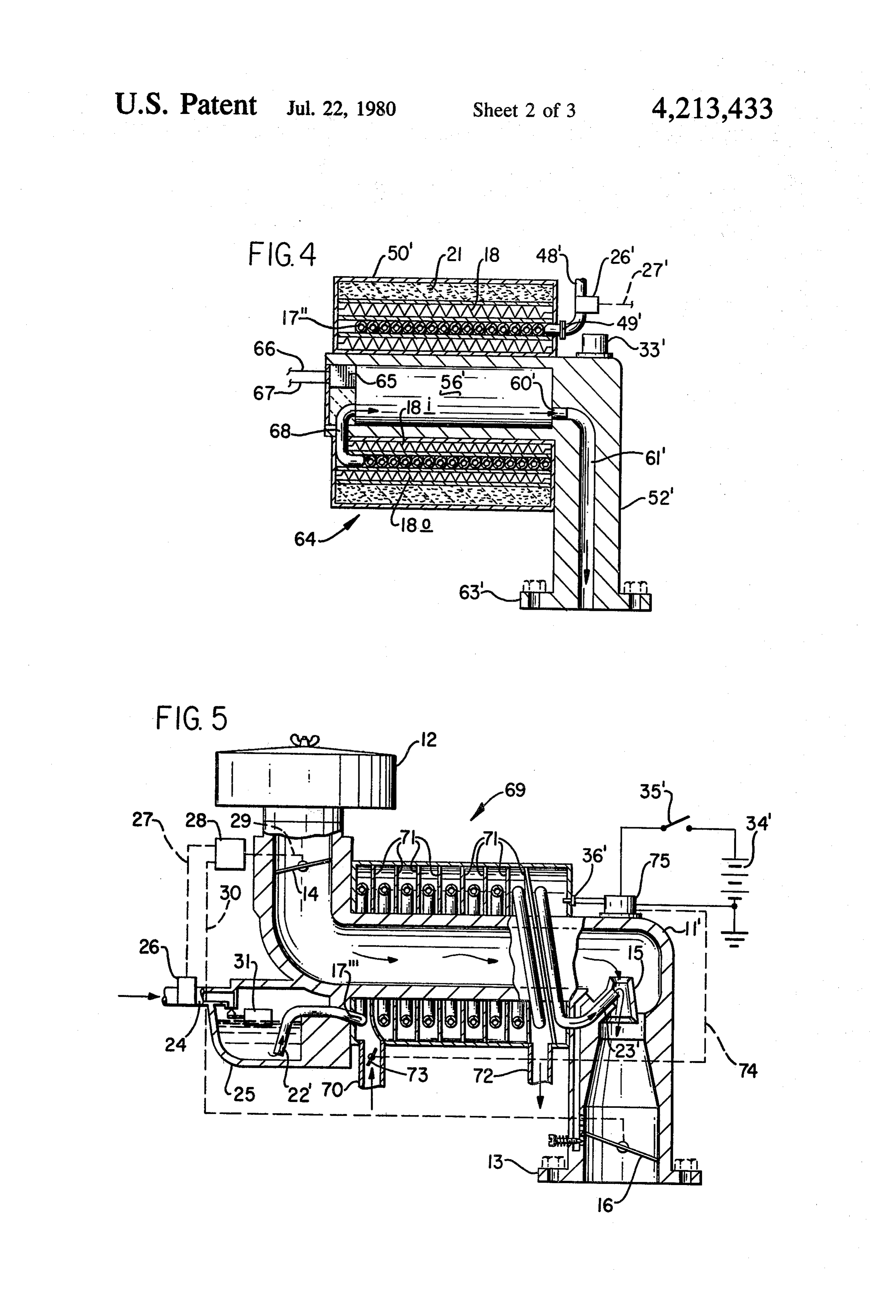
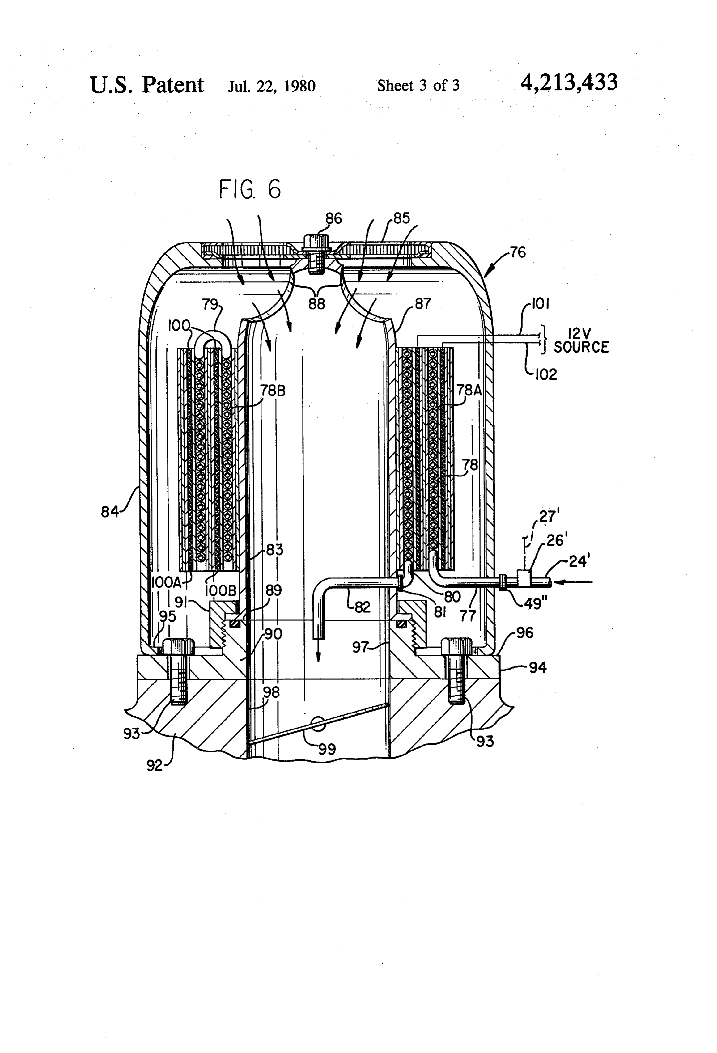
In the drawings: thereby activate the control 33 to close switch 32 and FIG. 1 represents a partially broken away and sec supply power to electrical heating element 18. Thermo tioned view of a liquid fuel to gas converter, for an couple element 36, mounted to sense temperature of the internal combustion engine, using an elongate heated coiled tube 17, in this instance near the output end of tubular element within which liquid fuel is transformed 30 tube 17, is connected by wires 37 and 38 to temperature to the molecular gaseous state and from which gaseous control 33 in order that the control may be caused to fuel is mixed with air being fed to the engine; open switch 32 via mechanical linkage 39 from tempera FIG. 2, an alternate electric heating element control ture control 33 whenever temperature sensed by ther system to the heating element control system in the mocouple element 36 exceeds a predetermined desired liquid fuel to gas converter of FIG. 1; 35 set level. When this occurs, reduced electric power FIG. 3, a liquid fuel to gas converter including a flow is provided through the temperature control 33 to compressor bringing molecular gaseous state fuel to the electric heating element 18.
pressure levels required for controlled feeding of gase In the alternate electric heating element control sys ous fuel to turbine or ramjet engines; tem 40 of FIG. 2, the electric heating element 18 has an FIG. 4, an alternate liquid fuel to gas converter em end connection to an output terminal 41 of electrical bodiment for turbine and ramjet engines; power generator 42 (or alternator). The other end of FIG. 5, a liquid fuel to gas converter much like the element 18 is connected through bimetallic switch 43 to embodiment of FIG. 1, using exhaust gas for heat input output terminal 44 of generator 42 that has two other to the elongate heated tubular element in place of an terminals 45 and 46 connected in common to ground. electric heating element system; and, 45 The bimetallic switch 43 is positioned in a gas converter FIG. 6, a broken away and sectioned view of another system much like positioning of thermocouple element liquid fuel to gas converter embodiment for engines. 36 in FIG. 1 to sense and react to temperature of the Referring to the drawings: coiled tube 17 so as to ensure substantially complete The liquid fuel to gas converter system 10 of FIG. 1, transformation of liquid fuel metered to the tube 17. for an internal combustion engine (not shown) is shown 50 The alternate embodiment of FIG. 3 presents a liquid to have a through air passage structure 11 extending fuel to gas converter 47 for internal combustion engines from air filter 12 to engine intake manifold mounting that includes turbine and ramjet engines. Liquid fuel is end 13 equipped with intake end butterfly valve 14, a fed through fuel line 48 and through fuel metering nee gaseous fuel and intake air mixing throat structure 15, dle valve 26' that is subject to control by a mechanical and an outlet end butterfly valve 16. The through air 55 drive linkage connection 27 with a drive throttle con passage structure 11 is shown to mount a coiled tube 17 trol (not shown) much like control 28 of FIG. 1. Fuel and heating element 18 containing housing assembly 19 line 48 is connected by coupling 49 to the input end of that surrounds (in annular relationship) a mid body the coiled tube 17" that is substantially entirely con portion 20 of the through air passage structure 11. The tained within fuel gasification chamber or housing as housing assembly 19 also encloses an outer annular sembly 50. Housing assembly 50 includes an inlet end insulation material band section 21 within which the member 51 and an outlet end member 52 that are inter heating element 18 is shaped and positioned such as to connected by a cylindrical outer housing shell 53 en be both radially inside and outside the coiled tube 17 as closing an annular insulation material band 21", an insu annular heating bands 18i and 18o for imparting con lation band support cylindrical member 54, within the trolled heat input to the coiled tube 17 such as to ensure 65 insulation material band 21", and an annular heat ele substantially complete transformation of liquid fuel ment 18' structure that is enclosed within cylindrical metered into the tube 17 at input end 22 to substantially member 54 and around generally cylindrical support completely gassified fuel at the outlet end 23. The fuel member 55. Cylindrical support member 55 intercon
Page 7
nects housing inlet and outlet end members 51 and 52 ing of an engine (not shown) to a spiral passageway enclosing and mounting in longitudinal orientation first formed with spiralled baffle walling 71 that follows the coiled tube. 17" and then a compressor 56 receiving coils of coiled tubing 17". The exhaust gases exit molecular gaseous state fuel from the output end 57 of through outlet pipe 72 after having passed through the coiled tube 17". Here again, coiled tube 17' is of such 5 spiral passageway imparting heat to the coiled tube 17' material, so sized, and of such longitudinal length in the process. The exhaust line pipe 70 is equipped with through the coil convoluted body thereof, that with a butterfly valve 73 that is control drive positioned via thermostatically regulated heat input from the heating mechanical drive linkage 74 from temperature control element 18", is such as to ensure therein substantially 75 as governed by temperature sensed by thermocouple complete transformation of liquid fuel to a molecular 10 element 36". Temperature control 75 is activated with gaseous state as the fuel is moving therethrough before power from battery 34 when switch 35' is closed for it reaches outlet end 57. The compressor 56, driven by heat control for tubing 17". Thermocouple element 36 motor 58 through drive shaft 59, compresses molecular may be repositioned for optimized heat control of the gaseous state fuel and supplies the compressed fuel from system. The heat input and control systems are such as outlet 60 through passage 61 in outlet end member 52 15 to ensure substantially complete transformation of liq that is formed with a boss 62 to mount motor 58 and a uid fuel to substantially completely gasified molecular connection mount flange 63 for connection to a turbine gaseous state fuel as the fuel is passed through coiled or ramjet engine (not shown) at an appropriate pressur tube 17". Parts having the same identification numbers ized fuel inlet location in the engine. with this embodiment as in the FIG. embodiment are In the embodiment of FIG. 4, another liquid fuel to 20 the same and function substantially the same in the gas converter 64 for turbine and ramjet internal com embodiment of FIG. 5.
bustion engines is presented that is a concentric for The liquid fuel to gas converter system 76 of FIG. 6 shortened design from the embodiment of FIG. 3. Liq is a vertically oriented embodiment with a fuel line 24' uid fuel is fed through fuel line 48' and through fuel feeding liquid fuel through a fuel metering needle valve metering needle valve 26' that, like with the FIG. 3 25 26 that is subject to control by a mechanical drive embodiment, is subject to control by a mechanical drive linkage connection 27 with a drive throttle control (not linkage connection 27 with a drive throttle control (not shown). The liquid fuel is passed through coupling 49" shown) much like control 28 of FIG. 1. Fuel line 48' is to the input end 77 of tubular coil 78, that is in the form connected by coupling 49' to the input end of the coiled of a two banked tubular coil 78 with outer coil 78A tube 17" that is substantially entirely contained within 30 connected to inner coil 78B by an interconnect loop 79, housing assembly 50'. The inlet end of housing assembly to gasified fuel outlet end 80 connected through cou 50' is also the outlet end with the coiled tube 17' and the pling 81 to gasified fuel outlet pipe 82 that extends compressor assembly 56' in concentric relation to each through air passage wall 83. The system 76 includes an other. The compressor assembly 56 that includes a outer vertical cylindrical casing 84 with a filter struc driving motor (not shown) is supplied power from 35 ture 85 at the top fastened as a casing 84 assembly with power and control box 65 that receives electric power a bolt 86 at the top to an inner cylindrical air passage through lines 66 and 67, and receives gasified fuel from member 87 including cylindrical wall 83 and air passage the output end 68 of coiled tube 17". The compressor opening 88 at the top. The inner cylindrical air passage assembly 56 compresses molecular gaseous state fuel member 87 is seated on the inner top 89 of mount mem and supplies the compressed fuel from outlet 60' 40 ber 90 by large nut clamp down member 91. Member 90 through passage 61" in outlet end member 52" that is is, in turn, mounted on the top of engine intake air and formed with a connection mount flange 63 for connec gas passage manifold member 92 by bolts 93 through tion to a turbine or ramjet engine (not shown) at an flange 94 of mount member 90. The bottom formed appropriate pressurized fuel inlet location in the engine. inward flange 95 of cylindrical casing 84 seats on the Please note that the housing assembly 50', just like with 45 top 96 of flange 94 of mount member 90 that is formed housing assembly 19 of FIG. 1, encloses an outer annu with an inner air and gas passage 97 in line with intake lar insulation band section 21 within which the heating air and gas passage 98 in manifold member 92 that con element 18 is shaped and positioned such as to be both tains butterfly valve 99 that may be connected for throt radially inside and outside the coiled tube 17' as annular tle control (detail not shown). The coiled tube structure heating bands 18i and 18o for imparting controlled heat 50 78 is heated by a double concentrically banked heating input to the coiled tube 17". This is to ensure substan element structure 100 with bank 100A outside of tube tially complete transformation of liquid fuel metered coil section 78A and bank 100B between the tube coil into the tube 17" at the input end through coupling 49' sections 78A and 78B with the heating structure 100 to substantially completely gasified fuel at the outlet supplied electric power through lines 101 and 102 in a end 68 from which it passes into compressor assembly 55 power supply system (not completely detailed). The 56". The power control for element 18 is supplied via coiled tube structure 78 with the heating element struc temperature control 33' and such power control cir ture 100 is mounted in position on the outside of air cuitry and elements that are shown with temperature passage member 87 by conventional means not shown control 33 of FIG. 1. in detail.
The liquid fuel to gas converter system 69 of FIG. 5 60 The coiled tubes in the different embodiments that is another embodiment very much like the embodiment are the elongate heated tubular element into which of FIG. 1 with exhaust gas from the exhaust system of liquid fuel is metered and from which fuel in the molec an engine supplying the heat required in place of the ular gasified state is passed have been, in test units, heating element 18 of FIG. 1. The control system for copper tubing. In one instance, the tubing was quarter heat input to the coiled tube 17' is also different from 65 inch copper tubing over 25 feet long formed into a coil. the temperature control 33 and associated heat control Obviously, other high heat conductive materials such as circuitry of FIG. 1. Exhaust line pipe 70 is connected to aluminum may be used in tubing for the coils in units in and conveys hot exhaust gases from exhaust manifold attaining substantially the same operational results. Fur
Page 8
ther, it should be noted that various other tubing diame trol means responsive to inputs from said temperature ters and lengths may be employed in balanced relation sensing means for varying control of said control means to the fuel demands of internal combustion engines they in controlling said temperature power media feed are used with and to the rate of controlled heat input to 6talS.
the coiled tubing such as to ensure substantially com 5 3. The liquid fuel to gas converter of claim 2, wherein plete transformation of liquid fuel to the molecular said temperature sensing means is a thermocouple posi gaseous state as the fuel is passed through the coiled tioned to sense temperature of said coil means at a de tube. sired location.
Whereas this invention is herein illustrated and de 4. The liquid fuel to gas converter of claim 1, wherein scribed with respect to several embodiments thereof, it 10 said coil means is formed as a single coil structure with should be realized that various changes may be made inlet and outlet connective means for said tubular ele without departing from essential contributions to the art ment means.
made by the teachings hereof. 5. The liquid fuel to gas converter of claim 4, wherein I claim: said heating system means includes two electric resis 1. In a liquid fuel to gas converter for internal com 15 tive element means cylindrical structures, one radially bustion engines: housing means; elongate fuel convey within said single coil structure and one radially outside ing means made of high heat conductive material of said single coil structure.
mounted within said housing means; said elongate fuel 6. The liquid fuel to gas converter of claim 1, wherein conveying means having a fuel inlet end constructed for said coil means is formed as a plurality of coil structures liquid fuel input from liquid supply means, and an outlet 20 in concentric relation.
end positioned for delivery of molecular gaseous state 7. The liquid fuel to gas converter of claim 6, wherein fuel to engine fuel intake means; a heating system with said electric resistance element means is formed into a heating element means mounted within said housing plurality of cylindrical structure sections with at least means to heat said elongate fuel conveying means suffi one of said cylindrical structure sections positioned ciently to ensure substantially complete transformation 25 between a set of two of said plurality of coil structures. of fuel from the liquid state to the molecular gasified 8. The liquid fuel to gas converted of claim 1, with state as fuel is passed through said elongate fuel convey said housing means also enclosing annular band insula ing means after initial warmup; wherein said elongate tion material means.
fuel conveying means is tubular element means formed 9. The liquid fuel to gas converter of claim 1, wherein primarily as coil means contained in foreshortened form 30 said converter is constructed with an air intake passage within said housing in an efficiently packaged structure; member having an air intake passage in line with an with said heating system means in close contiguous engine intake manifolding intake passageway when relation to said coil means for optimized heat transfer to mounted in place on the engine intake manifold. and through said coil means to the fuel being passed 10. The liquid fuel to gas converter of claim 9, through the tubular element means formed into said coil 35 wherein said converter is a vertically oriented unit with means; wherein said heating system means is in concen an air intake filter insert at the top of the converter tric relation with said coil means; said heating system housing means.
means includes an electric resistance element means 11. The liquid fuel to gas converter of claim 1, formed into a cylindrical structure in close contiguous wherein the tubing forming said coil means is tubing in relation to said coil means; and wherein an air intake 40 the range from approximately one sixteenth to one half passage structure is provided with an air passage for inch diameter tubing; and with the tubing length feeding intake air to an internal combustion engine; and through the convoluted longitudinal coiled length wherein a portion of said air passage is through, and thereof falling in the range of approximately two feet to surrounded by said heating system means and said coil thirty-five feet.
means for heat transfer to intake air prior to admission 45 12. The liquid fuel to gas converter of claim 1, of fuel in the heated molecular gasified state. wherein said tubular element means is from a class of 2. The liquid fuel to gas converter of claim 1, wherein high heat conductive materials including copper and said heating system means includes, temperature sensing aluminum. k k k k sk means; temperature power media feed means; and con- .
Provenance
- Collection
- Cited prior art
- Original PDF
- patentimages.storage.googleapis.com →
- Filed
- 1977-10-31
- Pages
- 8
- Method
- pdftotext (the PDF's own text layer) + pdftoppm 300dpi page scans
- Source
- Google Patents bibliographic record
- Granted
- 1980-07-22
- Inventors
- John C. Day
- Transcribed from
- patentimages.storage.googleapis.com →