patent · US4115078
Separation of gaseous mixtures of matter
19 September 1978
Page 1 — bibliographic record
United States Patent (19) (11) 4,115,078 Janner et al. 45) Sep. 19, 1978
54 SEPARATION OF GASEOUS MIXTURES OF 3,778,612 12/1973 Ashkin ...................... 331/DIG. 1 X MATTER FOREIGN PATENT DOCUMENTS (75) Inventors: Karl Janner, Erlangen; Klaus 2,094,967 2/1972 France ........................................... 55/2 Gregorius, Neunkirchen am Brand, 1,959,767 6/1971 Fed. Rep. of Germany ... 204/DIG. 11 both of Fed. Rep. of Germany 1,910,574 9/1970 Fed. Rep. of Germany ............. 55/100 301,930 11/1929 United Kingdom .......................... 55/3 73) Assignee: Kraftwerk Union Aktiengesellschaft,
Milheim, Ruhr, Fed. Rep. of OTHER PUBLICATIONS
Germany Fowles, G. R. Introduction to Modern Optics, Holt, (21) Appl. No.: 579,544 Rinehart and Winston, Inc., New York, 1968, pp. 10, 62, 22 Filed: May 21, 1975 233-235, 242, 243, 262, 264. Bennett, C. E., Physics, Barnes and Noble, Inc., New 51) Int. C.’................................................ B03C 3/38 York, 1952, p. 164.
52 U.S. Cl. ........................................... 55/2; 55/100; Primary Examiner-Frank W. Lutter 55/101; 204/DIG. 11; 250/251; 250/282; Assistant Examiner-Kathleen J. Prunner 250/423 P; 331/DIG. 1 Attorney, Agent, or Firm-Kenyon & Kenyon, Reilly, 58) Field of Search ......................................... 55/1-3, Carr & Chapin
282, 423 P; 331/DIG. 1 57 ABSTRACT 56 References Cited A gaseous jet of a mixture of matter or isotopes to be
2,836,750 5/1958 Weimer ................................. 55/2 X wave, e.g., a laser or maser beam. The required fre 2,959,677 11/1960 Robinson et al. ................ 250/423 P quency is in the vicinity of a resonant frequency of a 3,443,087 5/1969 Robieux et al. ......... 204/DIG. 11 X molecular dipole of the substance to be separated. For 3,484,603 12/1969 Bloom et al. ........................ 250/251 deflecting the mixture components and therefore, their 3,519,356 7/1970 Kroeger et al... 331/DIG. X separation, the forces on the molecular dipoles pro 3,532,879 10/1970 Braunstein et al... ... 250/251 duced by the electric and/or the magnetic field are 3,558,877 1/1971 Pressman ......... ... 250/25 utilized.
3,710,279 1/1973 Ashkin ................................... 55/2 X
3,772,519 11/1973 Levy et al. .............. 204/DIG. 11 X 12 Claims, 9 Drawing Figures
Page 2
Drawing sheet — no readable text.
Page 3
Drawing sheet — no readable text.
Page 4
FIG. 9 in longitudinal section shows modified appa
SEPARATION OF GASEOUS MIXTURES OF ratus for separating mixtures of matter by laser radia
DETAILED DESCRIPTION OF THE
BACKGROUND OF THE INVENTION INVENTION
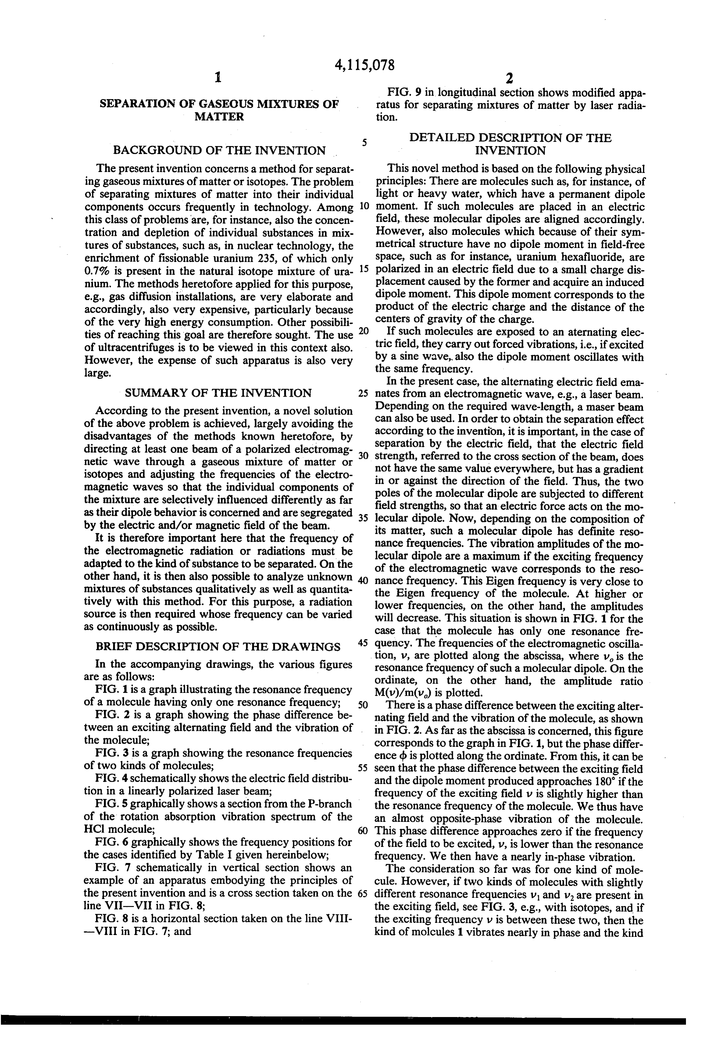
The present invention concerns a method for separat This novel method is based on the following physical ing gaseous mixtures of matter or isotopes. The problem principles: There are molecules such as, for instance, of of separating mixtures of matter into their individual light or heavy water, which have a permanent dipole components occurs frequently in technology. Among 10 moment. If such molecules are placed in an electric this class of problems are, for instance, also the concen field, these molecular dipoles are aligned accordingly. tration and depletion of individual substances in mix However, also molecules which because of their sym tures of substances, such as, in nuclear technology, the metrical structure have no dipole moment in field-free enrichment of fissionable uranium 235, of which only space, such as for instance, uranium hexafluoride, are 0.7% is present in the natural isotope mixture of ura polarized in an electric field due to a small charge dis nium. The methods heretofore applied for this purpose, placement caused by the former and acquire an induced e.g., gas diffusion installations, are very elaborate and dipole moment. This dipole moment corresponds to the accordingly, also very expensive, particularly because product of the electric charge and the distance of the of the very high energy consumption. Other possibili centers of gravity of the charge.
ties of reaching this goal are therefore sought. The use 20 If such molecules are exposed to an aternating elec of ultracentrifuges is to be viewed in this context also. tric field, they carry out forced vibrations, i.e., if excited However, the expense of such apparatus is also very the by a sine wave, also the dipole moment oscillates with large. same frequency.
In the present case, the alternating electric field ema
SUMMARY OF THE INVENTION 25 nates from an electromagnetic wave, e.g., a laser beam. According to the present invention, a novel solution can Depending on the required wave-length, a maser beam of the above problem is achieved, largely avoiding the according also be used. In order to obtain the separation effect disadvantages of the methods known heretofore, by separation tobythetheinvention, electric it is important, in the case of field, that the electric field directing at least one beam of a polarized electromag 30 strength, referred to the cross section of the beam, does netic wave through a gaseous mixture of matter or not have the same value everywhere, but has a gradient isotopes and adjusting the frequencies of the electro in or against the direction of the field. Thus, the two magnetic waves so that the individual components of poles of the molecular dipole are subjected to different the mixture are selectively influenced differently as far field strengths, so that an electric force acts on the mo as their dipole behavior is concerned and are segregated 35 lecular dipole. Now, depending on the composition of by the electric and/or magnetic field of the beam.
It is therefore important here that the frequency of its matter, such a molecular dipole has definite reso the electromagnetic radiation or radiations must be lecularfrequencies.
nance dipole are a
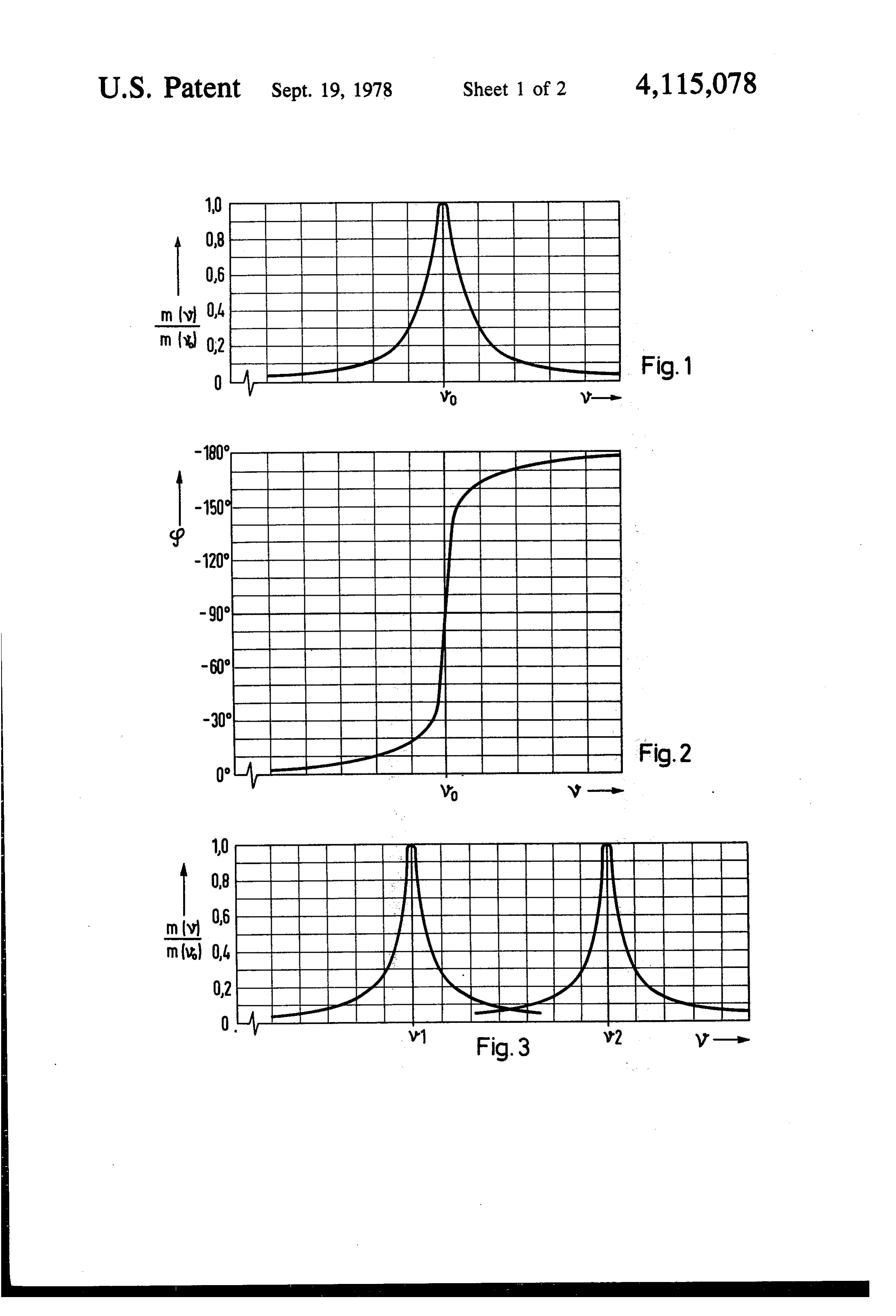
The vibration amplitudes of the mo maximum if the exciting frequency adapted to the kind of substance to be separated. On the of the electromagnetic wave corresponds to the reso other hand, it is then also possible to analyze unknown 40 nance frequency. This Eigen frequency is very close to mixtures of substances qualitatively as well as quantita the Eigen frequency of the molecule. At higher or tively with this method. For this purpose, a radiation lower frequencies, on the other hand, the amplitudes source is then required whose frequency can be varied will decrease. This situation is shown in FIG. 1 for the as continuously as possible. case that the molecule has only one resonance fre BRIEF DESCRIPTION OF THE DRAWINGS quency. The frequencies of the electromagnetic oscilla In the accompanying drawings, the various figures tion, v, are plotted along the abscissa, where v is the resonance frequency of such a molecular dipole. On the are as follows:
FIG. 1 is a graph illustrating the resonance frequency M(v)/m(v)onis plotted.
ordinate, the other hand, the amplitude ratio of a molecule having only one resonance frequency; 50 There is a phase difference between the exciting alter FIG. 2 is a graph showing the phase difference be nating field and the vibration of the molecule, as shown tween an exciting alternating field and the vibration of in FIG. 2. As far as the abscissa is concerned, this figure the molecule; corresponds to the graph in FIG. 1, but the phase differ FIG. 3 is a graph showing the resonance frequencies ence d is plotted along the ordinate. From this, it can be of two kinds of molecules; 55 seen that the phase difference between the exciting field FIG. 4 schematically shows the electric field distribu and the dipole moment produced approaches 180 if the tion in a linearly polarized laser beam; frequency of the exciting field v is slightly higher than FIG.5 graphically shows a section from the P-branch the resonance frequency of the molecule. We thus have of the rotation absorption vibration spectrum of the an almost opposite-phase vibration of the molecule. HCl molecule; 60 This phase difference approaches zero if the frequency FIG. 6 graphically shows the frequency positions for of the field to be excited, V, is lower than the resonance the cases identified by Table I given hereinbelow; frequency. We then have a nearly in-phase vibration. FIG. 7 schematically in vertical section shows an The consideration so far was for one kind of mole example of an apparatus embodying the principles of cule. However, if two kinds of molecules with slightly the present invention and is a cross section taken on the 65 different resonance frequencies v and v are present in line VII-VII in FIG. 8: the exciting field, see FIG. 3, e.g., with isotopes, and if FIG. 8 is a horizontal section taken on the line VIII the exciting frequency v is between these two, then the -VIII in FIG. 7; and kind of molcules 1 vibrates nearly in phase and the kind
Page 5
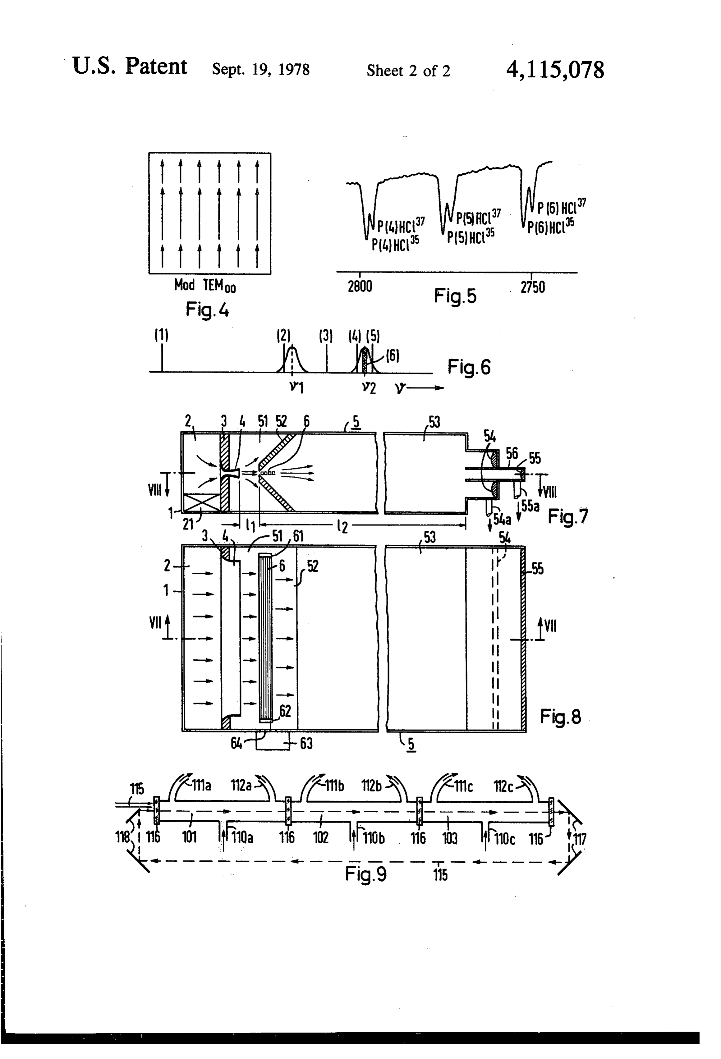
of molecules 2 nearly in opposite phase relative to the It follows from what has been said that the strongest exciting field. This means also that the two kinds of deflection effect occurs if the amplitude difference is molecules are deflected in an inhomogeneous exciting large and the deflection direction different. These deflection phenomena can be utilized for sepa field in opposite directions. 5 rating the molecules if the molecules are passed, for The distribution of the electric field, e.g., in a linearly polarized laser beam, is schematically shown in FIG. 4 instance, as a molecular jet or beam through the electro for one point in time. This distribution is called the magnetic wave. The deflection of the individual molec TEM mode. The field has only one direction and its ular dipoles then effects for them a specific change of direction in the molecular beam, Through collector intensity decreases, in or against the direction of the 10 zones distributed in space accordingly, the separated field, according to a function which can be influenced components of the molecular beam, which were origi by the design of the radiation source, i.e., for instance, nally intimately mixed, can then be intercepted sepa the laser. In the upper half-plane, dipoles vibrating in phase are deflected downward, and those vibrating in pointed rately. For the sake of completeness it should further be the opposite phase, upward; in the lower half, the direc 5 wave canout that the divergence of the electromagnetic tion of the deflection is the reverse, because of the oppo tion withinbe the decreased by adjusting the density distribu gas jet and/or the choice of the fre site gradient of the electric field. If all similar molecules quency of the electromagnetic wave regarding its posi are to be deflected only in one direction, then only one tion half-plane is utilized for one beam passage or an asym this is that the density of the gas in theThe relative to the resonance frequency. reason for gas jet zone metrical field distribution must be generated, where the influences the index of refraction of the gas jet. Since gas jet passes only through regions without reversal of 20 refraction is also dependent on frequency, adjustment of the field direction and the component of the gradient density or of frequency will influence the refraction or falling in the direction of the field.
If the exciting frequency of the electromagnetic wave divergence of the electromagnetic wave. An example of is higher or lower than the two resonance frequencies an embodiment of apparatus for carrying out this sepa v and v, then the two kinds of molecules have only a 25 ration willthese be described later. small mutual phase shift and are deflected in the same beBesides used for electric forces, magnetic forces can also separating different kinds of molecules. This direction. Their amplitudes, i.e., the absolute values of follows from the fact that vibrating electric charges of the dipole moments and therefore, the deflecting force, the polarized molecules constitute however, are considerably different, if the exciting fre 30 carrier is subjected to a deflection an a-c current whose force in the alternat quency is in the vicinity of a resonance frequency. In ing magnetic field in accordance with the law of induc the latter case, there then exists also a different deflec tion of the different kinds of molecules and therefore, a tion. The force vector then runs parallel to the direction (or counter-direction) of the electromagnetic wave, i.e., possibility of separating them.
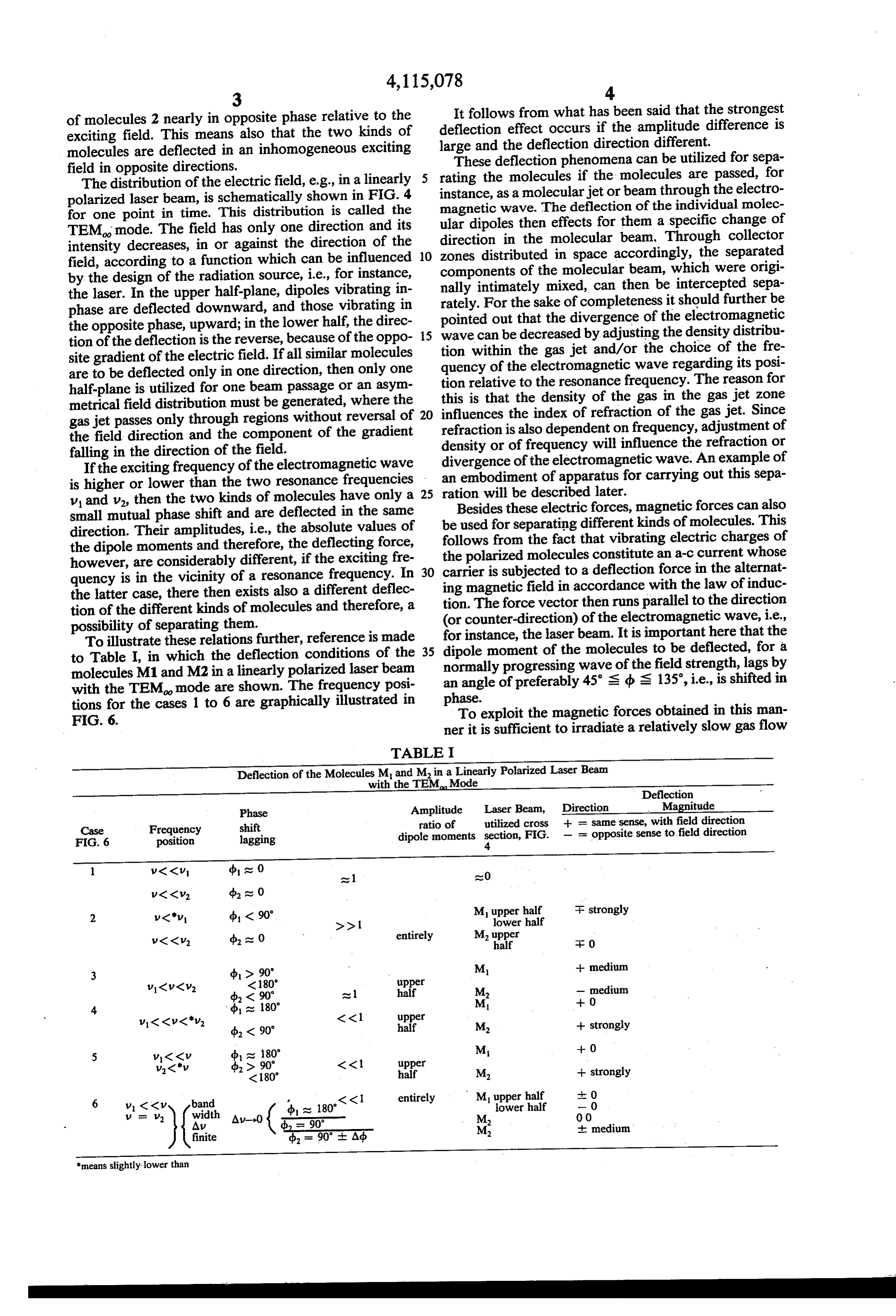
To illustrate these relations further, reference is made for instance, the laser beam. It is important here that the to Table I, in which the deflection conditions of the 35 dipole moment of the molecules to be deflected, for a normally progressing wave of the field strength, lags by molecules M1 and M2 in a linearly polarized laser beam an angle of preferably 45's b is 135, i.e., is shifted in with the TEM mode are shown. The frequency posi phase.
tions for the cases 1 to 6 are graphically illustrated in To exploit the magnetic forces obtained in this man
ner it is sufficient to irradiate a relatively slow gas flow
TABLE I
Deflection of the Moleculeswith
M the andTEM
Min aMode
Linearly Polarized Laser Beam
Deflection
Phase Amplitude Laser Beam, Direction Magnitude
Case Frequency shift ratio of utilized cross + = same sense, with field direction FIG. 6 position lagging dipole moments section, FIG. - = opposite sense to field direction
1 V<<V db at 0 at 1 at 0
2 v<v db (90' Mupper half F strongly
V<<v. db at 0 entirely M. upper
3 (b > 90' M + medium
4 d as 180" M -- 0
5 v<<v db at 180" M -- 0
6 V CKV band <<1 entirely Mupper half 0
Av Ao (, aso 90 M 'erhalf 0 06 finite db = 90 - Ad M. medium means slightly lower than
Page 6
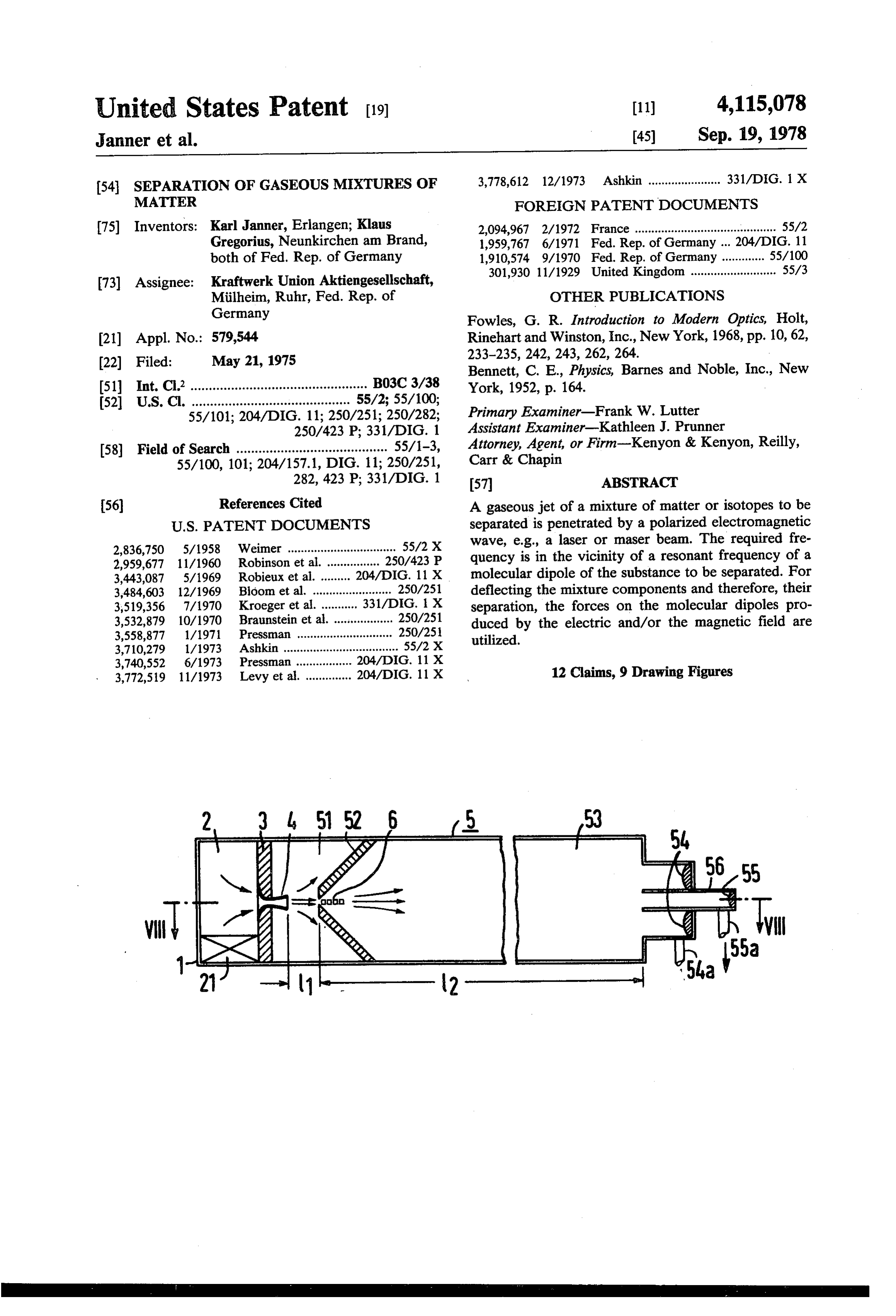
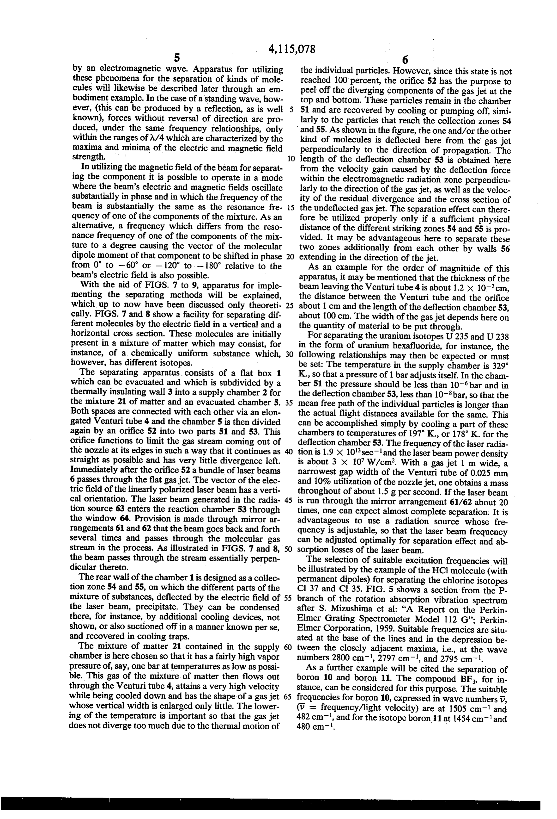
by an electromagnetic wave. Apparatus for utilizing the individual particles. However, since this state is not these phenomena for the separation of kinds of mole reached 100 percent, the orifice 52 has the purpose to cules will likewise be described later through an em peel off the diverging components of the gas jet at the bodiment example. In the case of a standing wave, how top and bottom. These particles remain in the chamber ever, (this can be produced by a reflection, as is well 51 and are recovered by cooling or pumping off, simi known), forces without reversal of direction are pro larly to the particles that reach the collection zones 54 duced, under the same frequency relationships, only and 55. As shown in the figure, the one and/or the other within the ranges of A/4 which are characterized by the kind of molecules is deflected here from the gas jet maxima and minima of the electric and magnetic field perpendicularly to the direction of propagation. The strength. 10 length of the deflection chamber 53 is obtained here In utilizing the magnetic field of the beam for separat from the velocity gain caused by the deflection force ing the component it is possible to operate in a mode within the electromagnetic radiation zone perpendicu where the beam's electric and magnetic fields oscillate larly to the direction of the gas jet, as well as the veloc substantially in phase and in which the frequency of the ity of the residual divergence and the cross section of beam is substantially the same as the resonance fre 5 the undeflected gas jet. The separation effect can there quency of one of the components of the mixture. As an fore be utilized properly only if a sufficient physical alternative, a frequency which differs from the reso distance of the different striking zones 54 and 55 is pro nance frequency of one of the components of the mix vided. It may be advantageous here to separate these ture to a degree causing the vector of the molecular two zones additionally from each other by walls 56 dipole moment of that component to be shifted in phase 20 extending in the direction of the jet. from 0 to -60 or -120' to . - 180' relative to the As an example for the order of magnitude of this beam's electric field is also possible. apparatus, it may be mentioned that the thickness of the With the aid of FIGS. 7 to 9, apparatus for imple beam leaving the Venturi tube 4 is about 1.2 x 10cm, menting the separating methods will be explained, the distance between the Venturi tube and the orifice which up to now have been discussed only theoreti 25 about 1 cm and the length of the deflection chamber 53, cally. FIGS. 7 and 8 show a facility for separating dif about 100 cm. The width of the gas jet depends here on ferent molecules by the electric field in a vertical and a the quantity of material to be put through. horizontal cross section. These molecules are initially For separating the uranium isotopes U235 and U238 present in a mixture of matter which may consist, for in the form of uranium hexafluoride, for instance, the instance, of a chemically uniform substance which, 30 following relationships may then be expected or must however, has different isotopes. be set: The temperature in the supply chamber is 329 The separating apparatus, consists of a flat box 1 K., so that a pressure of 1 bar adjusts itself. In the cham which can be evacuated and which is subdivided by a ber 51 the pressure should be less than 10 bar and in thermally insulating wall 3 into a supply chamber 2 for the deflection chamber 53, less than 10 bar, so that the the mixture 21 of matter and an evacuated chamber 5. 35 mean free path of the individual particles is longer than Both spaces are connected with each other via an elon the actual flight distances available for the same. This gated Venturi tube 4 and the chamber 5 is then divided can be accomplished simply by cooling a part of these again by an orifice 52 into two parts 51 and 53. This chambers to temperatures of 197 K., or 178' K. for the orifice functions to limit the gas stream coming out of deflection chamber 53. The frequency of the laser radia the nozzle at its edges in such a way that it continues as 40 straight as possible and has very little divergence left. tion is 1.9 x 10'sec and the laser beam power density is about 3 x 10 W/cm. With a gas jet 1 m wide, a
Immediately after the orifice 52 a bundle of laser beams narrowest gap width of the Venturi tube of 0.025 mm 6 passes through the flat gas jet. The vector of the elec and 10% utilization of the nozzle jet, one obtains a mass tric field of the linearly polarized laser beam has a verti throughout of about 1.5g per second. If the laser beam cal orientation. The laser beam generated in the radia 45 is run through the mirror arrangement 61/62 about 20 tion source 63 enters the reaction chamber 53 through times, one can expect almost complete separation. It is the window 64. Provision is made through mirror ar advantageous to use a radiation source whose fre rangements 61 and 62 that the beam goes back and forth quency is adjustable, so that the laser beam frequency several times and passes through the molecular gas can be adjusted optimally for separation effect and ab stream in the process. As illustrated in FIGS. 7 and 8, 50 sorption losses of the laser beam. the beam passes through the stream essentially perpen The selection of suitable excitation frequencies will dicular thereto. be illustrated by the example of the HCl molecule (with The rear wall of the chamber 1 is designed as a collec permanent dipoles) for separating the chlorine isotopes tion zone 54 and 55, on which the different parts of the Cl 37 and Cl 35. FIG. 5 shows a section from the P mixture of substances, deflected by the electric field of 55 branch of the rotation absorption vibration spectrum the laser beam, precipitate. They can be condensed after S. Mizushima et al: "A Report on the Perkin there, for instance, by additional cooling devices, not Elmer Grating Spectrometer Model 112 G'; Perkin shown, or also suctioned off in a manner known per se, Elmer Corporation, 1959. Suitable frequencies are situ and recovered in cooling traps. ated at the base of the lines and in the depression be The mixture of matter 21 contained in the supply tween the closely adjacent maxima, i.e., at the wave chamber is here chosen so that it has a fairly high vapor numbers 2800 cm, 2797 cm, and 2795 cm-l. pressure of, say, one bar attemperatures as low as possi As a further example will be cited the separation of ble. This gas of the mixture of matter then flows out boron 10 and boron 11. The compound BF, for in through the Venturi tube 4, attains a very high velocity stance, can be considered for this purpose. The suitable while being cooled down and has the shape of a gas jet 65 frequencies for boron 10, expressed in wave numbers v, whose vertical width is enlarged only little. The lower (v. = frequency/light velocity) are at 1505 cm and ing of the temperature is important so that the gas jet 482 cm, and for the isotope boron 11 at 1454 cm-land does not diverge too much due to the thermal motion of 480 cm-l. -
Page 7
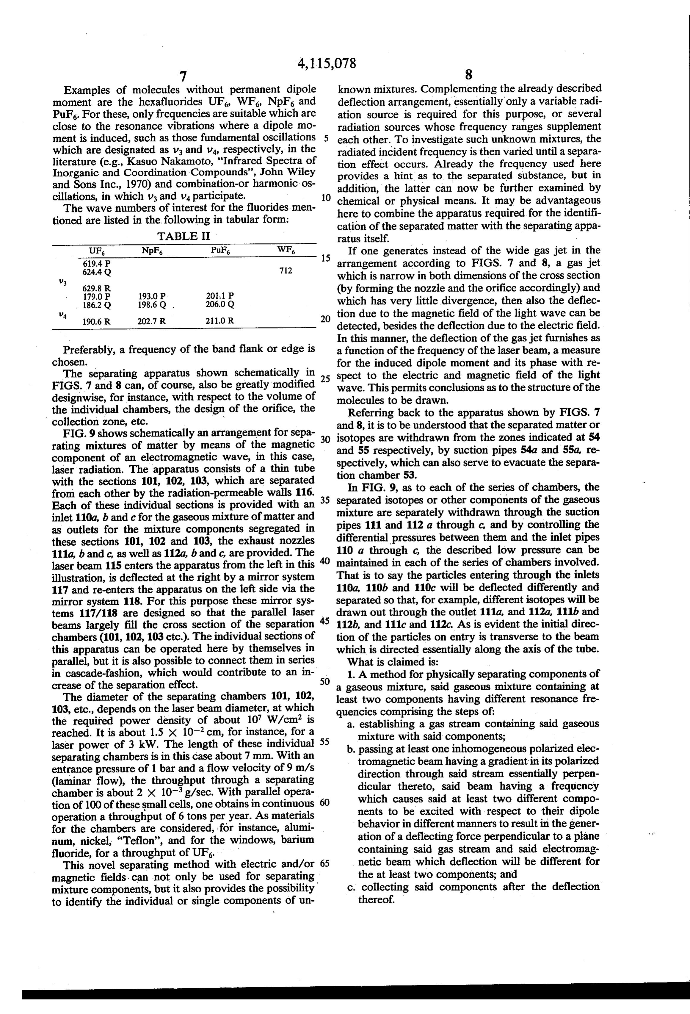
Examples of molecules without permanent dipole known mixtures. Complementing the already described moment are the hexafluorides UF, WF, NpF and deflection arrangement, essentially only a variable radi PuF. For these, only frequencies are suitable which are ation source is required for this purpose, or several close to the resonance vibrations where a dipole mo radiation sources whose frequency ranges supplement ment is induced, such as those fundamental oscillations each other. To investigate such unknown mixtures, the which are designated as V3 and V4, respectively, in the radiated incident frequency is then varied until a separa literature (e.g., Kasuo Nakamoto, "Infrared Spectra of tion effect occurs. Already the frequency used here Inorganic and Coordination Compounds', John Wiley provides a hint as to the separated substance, but in and Sons Inc., 1970) and combination-or harmonic os addition, the latter can now be further examined by cillations, in which V3 and V4 participate. O chemical or physical means. It may be advantageous The wave numbers of interest for the fluorides men here to combine the apparatus required for the identifi tioned are listed in the following in tabular form: cation of the separated matter with the separating appa TABLE II ratus itself. -
If one generates instead of the wide gas jet in the
arrangement according to FIGS. 7 and 8, a gas jet
which is narrow in both dimensions of the cross section
(by forming the nozzle and the orifice accordingly) and 1862 Q 1986 Q 2060 Q which has very little divergence, then also the deflec
1906 R 202.7 R 211.0R 20 tion due to the magnetic field of the light wave can be detected, besides the deflection due to the electric field.
In this manner, the deflection of the gas jet furnishes as
Preferably, a frequency of the band flank or edge is a function of the frequency of the laser beam, a measure chosen. for the induced dipole moment and its phase with re The separating apparatus shown schematically in 25 spect to the electric and magnetic field of the light FIGS. 7 and 8 can, of course, also be greatly modified wave. This permits conclusions as to the structure of the designwise, for instance, with respect to the volume of molecules to be drawn.
the individual chambers, the design of the orifice, the Referring back to the apparatus shown by FIGS. 7 collection zone, etc. and 8, it is to be understood that the separated matter or FIG. 9 shows schematically an arrangement for sepa 30 isotopes are withdrawn from the zones indicated at 54 rating mixtures of matter by means of the magnetic and 55 respectively, component of an electromagnetic wave, in this case, spectively, which canbyalsosuction serve pipes 54a and 55a, re to evacuate the separa laser radiation. The apparatus consists of a thin tube tion chamber 53.
with the sections 101, 102, 103, which are separated In FIG. 9, as to each of the series of chambers, the from each other by the radiation-permeable walls 116. 35 separated
Each of these individual sections is provided with an mixture areisotopes or other components of the gaseous separately withdrawn through the suction inlet 110a, b and c for the gaseous mixture of matter and as outlets for the mixture components segregated in pipes 111 and 112 a through c, and by controlling the these sections 101, 102 and 103, the exhaust nozzles differential pressures between them and the inlet pipes 111a, b and c, as well as 112a, b and c, are provided. The 110 a through c, the described low pressure can be laser beam 115 enters the apparatus from the left in this maintained in each of the series of chambers involved. illustration, is deflected at the right by a mirror system That is to say the particles entering through the inlets 117 and re-enters the apparatus on the left side via the 110a, 110b and 110c will be deflected differently and mirror system 118. For this purpose these mirror sys separated so that, for example, different isotopes will be tems 117/118 are designed so that the parallel laser drawn out through the outlet 111a, and 112a, 111b and beams largely fill the cross section of the separation 45 112b, and 111c and 112c. As is evident the initial direc chambers (101, 102,103 etc.). The individual sections of tion of the particles on entry is transverse to the beam this apparatus can be operated here by themselves in which is directed essentially along the axis of the tube. parallel, but it is also possible to connect them in series What is claimed is:
in cascade-fashion, which would contribute to an in 50 1. A method for physically separating components of crease of the separation effect. a gaseous mixture, said gaseous mixture containing at The diameter of the separating chambers 101, 102, least two components having different resonance fre 103, etc., depends on the laser beam diameter, at which quencies comprising the steps of: the required power density of about 10 W/cm is a. establishing a gas stream containing said gaseous reached. It is about 1.5 x 10 cm, for instance, for a laser power of 3 kW. The length of these individual 55 b. mixture with said components; passing at least one inhomogeneous polarized elec separating chambers is in this case about 7 mm. With an tromagnetic beam having a gradient in its polarized entrance pressure of 1 bar and a flow velocity of 9 m/s direction through said stream essentially perpen (laminar flow), the throughput through a separating dicular thereto, said beam having a frequency chamber is about 2 X 10 g/sec. With parallel opera which causes said at least two different compo tion of 100 of these small cells, one obtains in continuous nents to be excited with respect to their dipole operation a throughput of 6 tons per year. As materials for the chambers are considered, for instance, alumi behavior in different manners to result in the gener num, nickel, "Teflon', and for the windows, barium ation of a deflecting force perpendicular to a plane fluoride, for a throughput of UF6. containing said gas stream and said electromag This novel separating method with electric and/or 65 netic beam which deflection will be different for magnetic fields can not only be used for separating the at least two components; and mixture components, but it also provides the possibility c. collecting said components after the deflection to identify the individual or single components of un thereof.
Page 8
2. The method of claim 1 in which to separate the b. passing at least one polarized electromagnetic components by the magnetic field of said beam the wave beam, having electric and magnetic fields beam's electric and magnetic fields oscillate substan oscillating substantially in phase as in a normally tially in phase and its frequency is substantially the same progressing wave, through the mixture with the as the resonance frequency of one of the components of 5 phase of the dipole moment of the molecules of the said mixture. components of the mixture to be deflected being 3. The method of claim 1 in which said beam is radi shifted by said beam so that said dipole moment ated by a laser or maser. lags by an angle approximately between the limits 4. The method of claim 1 and further including the O of 45 and 135, in the direction of the axis of the elongated chamber, said beam having a frequency step of reflecting said beam so that it passes back and which causes the at least two components of said forth through said mixture a plurality of times, mixture to be differentially influenced in regard to 5. The method of claim 1 wherein of said step of their dipole behavior whereby said beam will act forming a gas stream comprises forming a sharply fo thereupon to cause deflection of the components of cused jet. 15 the mixture in different directions; and 6. The method of claim 5 and further including the c. collecting said components after deflection. step of reducing the divergence of said beam due to its 9. The method according to claim 8 in which the frequency dependent index of refraction by adjusting frequency of said beam differs from the resonance fre the density distribution within said jet. quency of one of the components of said mixture to a 7. The method according to claim 1 and further in 20 degree causing the vector of the molecular dipole mo cluding the step of reducing the divergence of said ment of that component to be shifted in phase relative to beam resulting from its frequency dependent index of the beam's electric field by an amount which deviates refraction by adjusting the frequency of said beam rela no more than 60 from the vector of the electric field so as to fall within one of the ranges 0° to -60 or -120' tive to the molecular resonance frequency of one of said 25 to components. - 180.
8. A method for physically separating components of 10. The method according to claim 8 wherein said a gaseous mixture, said mixture containing at least two beam is radiated by one of a laser or a maser. 11. The method according to claim 8 and further components having different resonance frequencies including the step of reflecting said beam so that it comprising the steps of: 30 passes back and forth through said mixture a plurality of a. establishing a flow of said gaseous mixture by cre times.
ating a differential pressure in an elongated cham 12. The method according to claim 8 and further ber having a central axis, the chamber having an including the step of reflecting said beam so as to pass inlet and a pair of spaced outlets on opposite sides through said mixture in only the same direction a plural thereof, said inlet opening into said chamber essen 35 ity of times.
tially transversely to the axis thereof; k sk
Provenance
- Collection
- Cited prior art
- Original PDF
- patentimages.storage.googleapis.com →
- Filed
- 1975-05-21
- Pages
- 8
- Method
- pdftotext (the PDF's own text layer) + pdftoppm 300dpi page scans
- Source
- Google Patents bibliographic record
- Granted
- 1978-09-19
- Inventors
- Karl Janner; Klaus Gregorius; Kraftwerk Union AG
- Transcribed from
- patentimages.storage.googleapis.com →