patent · US5614078
Method and apparatus for removing nitrates from water
25 March 1997
Page 1 — bibliographic record
United States Patent 19 11) Patent Number: 5,614,078 Lubin et al. (45) Date of Patent: Mar 25, 1997
54) METHOD AND APPARATUS FOR 5,376,240 12/1994 Kaczur et al. .......................... 204/128
REMOVING NITRATES FROM WATER
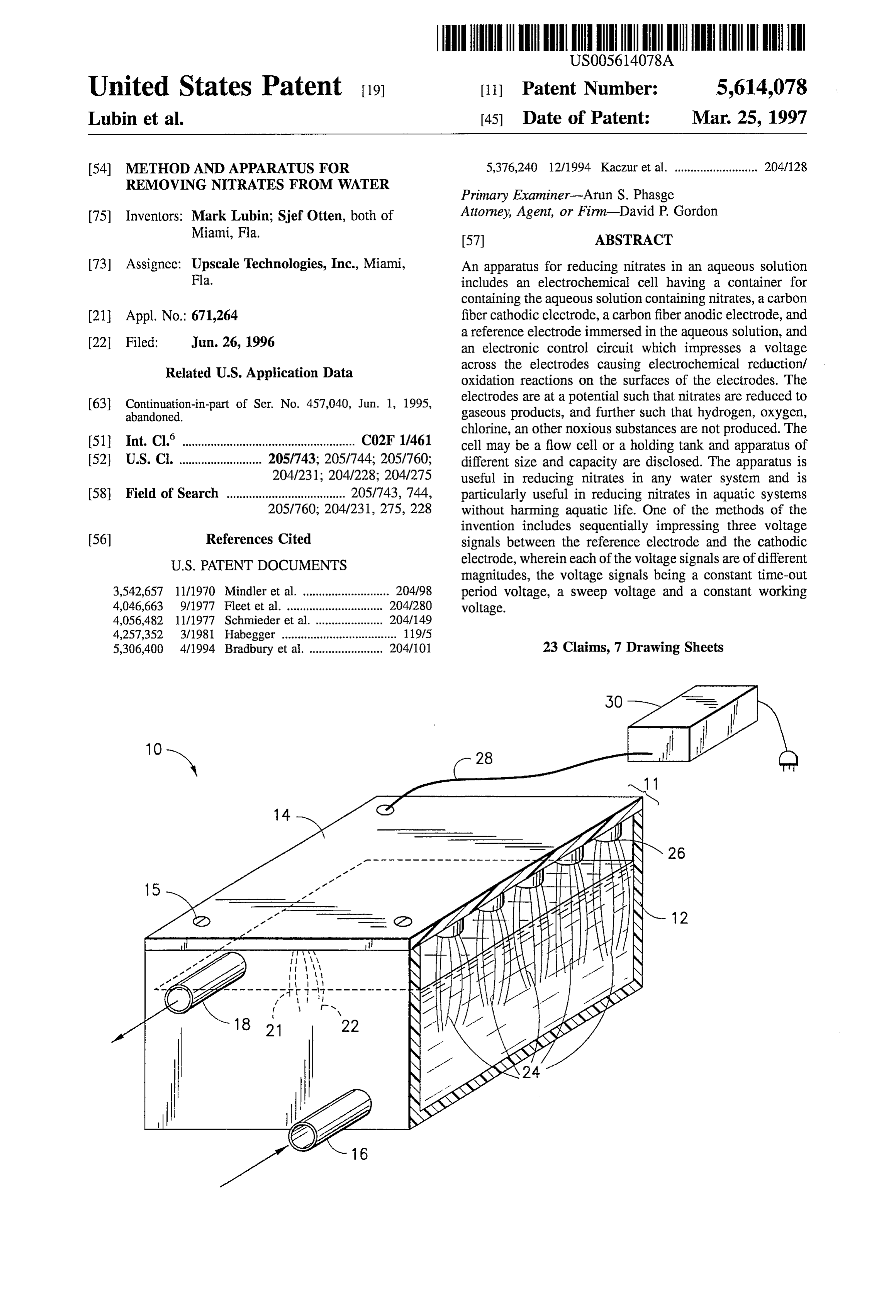
Primary Examiner-Arun S. Phasge 75) Inventors: Mark Lubin; Sief Otten, both of Attorney, Agent, or Firm-David P. Gordon Miami, Fla. (57) ABSTRACT 73) Assignec: Upscale Technologies, Inc., Miami, An apparatus for reducing nitrates in an aqueous solution Fla. includes an electrochemical cell having a container for containing the aqueous solution containing nitrates, a carbon 21 Appl. No.: 671,264 fiber cathodic electrode, a carbon fiberanodic electrode, and
a reference electrode immersed in the aqueous solution, and an electronic control circuit which impresses a voltage
Related U.S. Application Data across the electrodes causing electrochemical reduction/ oxidation reactions on the surfaces of the electrodes. The 63 Continuation-in-part of Ser. No. 457,040, Jun. 1, 1995, electrodes are at a potential such that nitrates are reduced to abandoned. gaseous products, and further such that hydrogen, oxygen, chlorine, an other noxious substances are not produced. The (51) Int. Cl." ......................................... CO2F 1/461 cell may be a flow cell or a holding tank and apparatus of I52 U.S. C. .......................... 205/743; 205/744; 205/760; different size and capacity are disclosed. The apparatus is 204/231; 204/228; 204/275 useful in reducing nitrates in any water system and is 58 Field of Search ..................................... 205/743, 744, particularly useful in reducing nitrates in aquatic systems 205/760; 204/231, 275, 228 without harming aquatic life. One of the methods of the invention includes sequentially impressing three voltage
I56) References Cited signals between the reference electrode and the cathodic
magnitudes, the voltage signals being a constant time-out 3,542,657 11/1970 Mindler et al. ........................... 2O4/98 period voltage, a sweep voltage and a constant working 4,046,663 9/1977 Fleet et al. .............. ... 204/280 voltage.
4,056,482 11/1977 Schmieder et al. . ... 204/149 4,257,352 3/1981 Habegger .................................... 119/5 5,306,400 4/1994 Bradbury et al. ....................... 204/101 23 Claims, 7 Drawing Sheets
Page 2
Drawing sheet — no readable text.
Page 3
Drawing sheet — no readable text.
Page 4
Drawing sheet — no readable text.
Page 5
Drawing sheet — no readable text.
Page 6
Drawing sheet — no readable text.
Page 7
Drawing sheet — no readable text.
Page 8
Drawing sheet — no readable text.
Page 9
METHOD AND APPARATUS FOR animals as well as the cause of “blue baby syndrome' in REMOVING NETRATES FROM WATER heavy agricultural regions.
Still another source of nitrate pollution exists in areas
This application is a continuation-in-part of U.S. Ser. No. where septic tanks and water wells coexist in close prox 08/457,040, filed on Jun. 1, 1995, the complete disclosure of 5 imity. This situation is quite common in New England where which is hereby incorporated by reference now abandoned. older septic tanks commonly leak nitrogenous waste into well aquifers rendering the water undrinkable.
BACKGROUND OF THE INVENTION The most common problem in closed aquatic systems, however, lies in aquaculture. Contaminated fishing waters 1. Field of the Invention 10 pose serious economic and health problems today when This invention relates generally to a device for removing demand for food fish is very high. So-called “wild” fishing nitrates from water, and this invention specifically relates to waters can be contaminated by nearby or upstream sources a device for removing nitrates from aquatic systems to of nitrogen, such as crop or poultry farming operations reduce the toxicity of the water in such systems to living has which allow nitrogenous waste to run off into a river. This organisms. 15 been a documented problem in the waters of the Neuse River in North Carolina, for example. There, upstream hog 2. State of the Art farming operations introduced nitrogenous waste into the Nitrate contamination is a serious problem in many river which eventually raised the level of nitrates in the aquatic systems. The primary source of dissolved nitrates is downstream fishing region. The toxicity of the nitrates in run-off water containing nitrogenous animal waste (urine, 20 caused the fish to become biologically stressed and more feces, uneaten food, decayed tissues, etc.) from poultry, susceptible to disease. People who consumed the diseased dairy cattle, hogs, and aquacultured species. The second fish became extremely ill, and consequently, the local fish largest source of nitrate contaminated water is the process polluted eries suffered significant economic loss. Other nitrogen ing water used to clean and prepare poultry and meat food Okeechobee, areas include the Everglades south of Lake products. This water is heavily loaded with nitrates and it is 25 contributor toFla. where the sugar industry has been a major typically stored for use in crop irrigation. The water is used practical solution to dateupsets.
ecological In South Florida, the most has been to plant nitrogen con as a crop irrigant only to the extent that the crops absorb suming crops in the affected areas, but this method is very nitrates. That it, the run-off irrigation water will still contain slow acting and requires large planted tracts. nitrates. Thus, the third most prominent source of nitrate Nitrogen pollution of fishing waters has become so com contaminated water is run-off water from nitrate fertilized 30 crop fields. mon, that commercial food fisheries have turned their efforts to pond aquaculture or fish farms where the conditions of the
Nitrate contamination is a serious problem because water can be more tightly controlled. However, even in these nitrates are poisonous to human and animal life. Nitrog "aquarium' environments, nitrogenous waste can be a seri enous waste generally occurs as three highly soluble species: ous problem due to a high density of aquatic livestock. As ammonia, nitrite, and nitrate. Ammonia is the most toxic of 35 used herein, the term "aquarium” refers to both relatively the three. Nitrites are known to be carcinogens and nitrates large fish farms containing many millions of gallons of water are toxic at somewhat higher levels of concentration. How as well as relatively small pet fish aquaria containing thou ever, nitrates consumed by humans and animals are con sands, hundreds, or even several gallons of water. verted into the more toxic nitrites during digestion. Natu All multi-cellular animal life-forms in aquarium environ rally occurring bacteria help to alleviate part of the problem 40 ments give off nitrogenous waste in the form of ammonia as of nitrogenous waste contamination by converting ammonia a direct result of physiological, respiratory and metabolic into nitrites and nitrites into nitrates. These aerobic nitrifying activity. Most marine organisms, especially soft-bodied bacteria oxidize ammonia to nitrite, and nitrite to nitrate, invertebrates such as corals that are typically found in respectively, as part of their metabolic and respiratory pro aquarium environments, have a very low tolerance for cesses. Under the right conditions, i.e. anaerobic and in the 45 ammonia and nitrite, and only a slightly better tolerance for presence of food molecules, nitrates become a source of nitrate. In aquaria, ammonia and nitrite reach toxic levels at oxygen to anaerobic bacteria and the nitrates are converted approximately 0.25 parts per million (ppm), which is a level to Nitrogen gas. much higher than that found naturally in sea water. The level In open aquatic systems, such as in oceans and seas, the of nitrates in sea water is approximately 2-5 ppm. In the sheer volume of water and the preponderance of nitrifying 50 open ocean, nitrate levels are controlled by dilution and by bacteria typically maintains the concentration of nitrogenous anaerobic bacteria which consume nitrates as an oxygen waste at safe levels. In smaller open aquatic systems which source for metabolism. In closed marine systems, nitrates are vulnerable to land based pollution, such as lakes and accumulate until their concentration is reduced by periodic aquifers which are near farms, the ecology of the aquatic water changes or by pockets of an anaerobic bacterial system may be insufficient to maintain a low level of 55 system. Water changes of fifteen percent every two weeks nitrates. In closed aquatic systems, such aquaculture ponds are typical. One must change the water regularly to keep the and aquaria, active steps must be taken to maintain safe marine life alive. This necessity can be extremely expensive levels of nitrogenous waste, or to avoid contamination of the inland, where natural sea water is not available and purified water. For example, in farming areas, it is common to water must be mixed with artificial sea salts. Moreover, in monitor the levels of nitrates in sources of drinking water 60 the case of aquaculture ponds, each pond must be com and to avoid drinking contaminated water when the levels pletely drained at least once per year so that nitrate muck can are too high. Pregnant women and children are often advised be scraped up from the bottom of the pond. A typical to drink only bottled water. The U.S. Environmental Pro commercial pond is five to ten acres, about ten feet deep, and tection Agency has set the maximum acceptable level of contains approximately fifteen to thirty million gallons of nitrates in drinking water at 10 ppm. Nitrates in drinking 65 water. The nitrate muck removed from these ponds is water are recognized to be the single largest causative considered to be toxic waste by some regulatory agencies mechanism of digestive tract cancers in humans and farm and disposal is a severe problem.
Page 10
It is known to take advantage of bacterial anaerobic NO and N2O is passed through a catalyst bed producing N. metabolic capability in order to reduce nitrate levels in and H2O. The formation of NH and H2, indicates very high aquaria. Water is pumped from the aquarium into a holding current densities, which would also cause the formation of tank where a filter pad is populated with chemoautotrophic Cl gas from salt water, and is thus not suitable for salt water bacteria. Methanol and other nutrients are introduced into applications. As mentioned above, NH is poisonous to the holding tank to drive the bacteria into anaerobic metabo aquatic life. The formation of H2 results in a change of pH, lism and to provide a source of carbohydrates (methanol which, if more than slight, cannot be tolerated by aquatic being the simplest carbohydrate). While the water is slowly life.
circulated for several hours, the bacteria use the nitrate ions The U.S. Pat. No. 4.212,724 patent discloses an oxidation as an oxygen source to consume the carbohydrates as food. 10 and coagulation method and apparatus suitable for use with At a programmed time the water in the tank is pumped back aquariums which includes a plurality of electrodes disposed into the aquarium and a new batch of water to be treated is in a chamber connected to a source of e.m.f. (A.C.) and a obtained. Those skilled in the art will recognize that metha plurality of electrically conductive particles. The electrodes nol is poisonous and must be used carefully in this system, lest the aquarium water be contaminated with unconsumed 15 ber so that theymounted are preferably by opposite side walls of the cham extend horizontally, substantially parallel to methanol. For this reason and other economic considerations (e.g. the cost of the methanol and the nutrients), this system each other. Oxidation of nitrogenous waste does not remove is impractical for the treatment of drinking water or com dissolved nitrates, as nitrates can only be removed by mercial fish pond water. reduction processes.
Electrolysis is presently known to be used in certain 20 water The U.S. Pat. No. 3,891,535 patent describes an aquarium systems for the removal of certain undesirable and/or toxic treatment apparatus utilizing two or more plates substances from water. Electrolysis involves electrochemi spaced apart and insulated from each other. A power source is provided for oppositely polarizing juxtaposed plates. A cal reactions requiring at least two electrodes, usually metal low voltage field is periodically reversed to prevent any lic, an anode and a cathode. In general, corrosion is a very common problem when metals come in contact with water, 25 oxygen, of buildup may impurities on the plates. Released gases, such as be carried to the bottom of the bodies of water particularly with salt water, and is particularly a problem to enhance the aerating effect and the sterilization of the while current flows through the electrodes. Marine life Water.
cannot tolerate abnormally high levels of metallic ions or corrosion products, particularly in a closed system. Most Both the U.S. Pat. No. 4,212,724 and U.S. Pat. No. electrode materials currently available are not suitable for 30 3,891,535 patents disclose the formation of large amounts of nitrate reduction in marine aquarium applications for several hydrogen, oxygen and chlorine, which are toxic to aquatic life and corrosive to stainless steel and other metal elec reasons: (1) most non-noble metals, such as copper, corrode trodes.
in sea water; (2) many electrode materials, such as copper, mercury and lead, are poisonous to marine life; (3) since The U.S. Pat. No. 772 patent describes a method and most noble metals are excellent catalysts for the hydrogen 35 apparatus for electrically inhibiting bacteria growth in ion reduction reaction, the hydrogen evolution reaction will aquariums including electrodes connected to a D.C. power proceed at a reaction rate many times larger than the nitrate SOUICC.
reduction reaction rate, causing the pH of the sea water to The U.S. Pat. No. 352 patent discloses a protozoan increase beyond acceptable limits for marine life survival; marine life inhibitor for use with an aquarium which (4) the electrode materials result in chlorine generation 40 includes a pair of carbon rod electrodes connected to an A.C. which, even in extremely low concentrations, is highly toxic power source and positioned in a stream of water to termi to marine life. The only way to prevent chlorine generation nate the protozoan life forms in the water passing between is to decrease the anodic current density by greatly increas the electrodes. The U.S. Pat. No. 352 patent reveals that the ing the anode to cathode surface area ratio, which would also exact electrical and physiological phenomena are not fully result in a device of immense size. In addition, the bulk 45 understood, but that the protozoan life forms undergo life processing of nitrate in any water system requires a large altering experiences.
electrode surface area which would result in a device of Neither the U.S. Pat. No. 772 patent nor the U.S. Pat. No. immense size. 352 patent address the issue of nitrate reduction. Further, Devices exist which use electrolysis to remove toxic the 772 system uses galvanized wire electrodes, which can substances from aqueous systems. Such devices are dis 50 be poisonous to marine life.
closed in U.S. Pat. No. 4,956,057 to Stucki et al., (the U.S. The U.S. Pat. No. 657 patent demonstrates the viability Pat. No. 057 patent), U.S. Pat. No. 4,212,724 to Moeglich of reducing nitrates using certain metal electrodes (copper, (the U.S. Pat. No. 724 patent), U.S. Pat. No. 5,148,772 to lead, tin, iron, silver, cadmium, platinum, cobalt, nickel, and Kirschbaum (the U.S. Pat. No. 772 patent), U.S. Pat. No. alloys thereof) which he found to be good electro-catalysts 4,257,352 to Habegger (the U.S. Pat. No. 352 patent), U.S. 55 for nitrate reduction. This process has several disadvantages Pat. No. 3,891,535 to Wikey (the U.S. Pat. No. 535 patent), including heat generation, and the requirement of relatively U.S. Pat. No. 3,542,657 to Mindler (the U.S. Pat. No. 657 high current densities and voltages. These disadvantages patent), and in U.S. Pat. No. 4,056,482 to Schmeider (the together with the unsuitability of metal electrodes make this U.S. Pat. No. 482 patent), all incorporated herein by ref process unsuitable for potable water treatment or aquatic life erence. While these devices use electrolysis to a certain 60 support systems. While the U.S. Pat. No. 482 patent pro degree of effectiveness, some of the above-mentioned prob poses a system of nitrate reduction using graphite electrodes, lems are inherent in them, as described below. the reaction requires the addition of cations such as copper, The U.S. Pat. No. 057 patent describes a process for lead, or titanium in order to compensate for the poor removal of nitrites and nitrates from an aqueous solution by electro-catalytic behavior of graphite. In actual practice, the means of electrolysis. The aqueous solution is fed to a 65 graphite shown in the U.S. Pat. No. 482 patent is merely a separate cathode space of the electrochemical cell. Gas substrate on which copper, lead, or titanium plates out and formed by the electrolytic reduction, containing H2, NH, the "electrode' actually becomes copper, lead, or titanium.
Page 11
S 6
As mentioned above, these metals are unacceptable for use In still another aspect of the preferred embodiment, the in aquatic systems. surfaces of the cathodic and/or anodic electrodes are either
SUMMARY OF THE INVENTION
chemically or electrochemically modified. With treated cathodic and/or anodic electrodes, the anodic electrode to
It is therefore an object of the invention to provide a 5 cathodic electrode surface area ratio is in the range of 5:1 to system which reduces nitrates in aquatic systems without 15:1.
changing the pH appreciably. An exemplary embodiment of a relatively small scale It is also an object of the invention to provide a system system is disclosed in which the flow rate of the aqueous which reduces nitrates in aquatic systems without the for O solution through a flow cell is in the range of 50 to 250 mation of substances which are toxic to aquatic life. gallons per hour. Other embodiments of the invention Yet another object of the invention is to provide a system include holding tanks with circulation loops and large tanks which reduces nitrates in marine and other aqueous systems having baffles and multiple serial sets of electrodes. The which uses electrodes which are not poisonous to aquatic larger systems according to the invention process aqueous life. solution at the rate of 1000 to 1500 gallons per minute.
Still another object of the invention is to provide a system The system of the invention preferably uses PAN carbon which reduces nitrates in marine and other aqueous Systems fiber electrodes which are not poisonous to aquatic life, do which uses electrodes which will not corrode in such sys not corrode, and do not release toxic corrosion products into tenS.
the water. The use of a silver/silver chloride reference
It is another object of the invention to provide a system 20 electrode easier to requires less set-up and calibration and is thus use. The extremely high surface area to volume which reduces nitrates in marine and other aqueous systems ratio of the material used for cathodic and anodic electrodes without the need for extremely large flow cells. allows appreciable bulk nitrate reduction in a reasonably It is yet another object of the invention to provide a sized flow cell. The voltage pattern and magnitudes of system which reduces nitrates in water and which may be 25 voltage applied to the electrodes maximize the life and used in both large and small aquatic systems usefulness of the electrodes while preventing the production It is also an object of the invention to provide a system of toxic substances such as chlorine. which reduces nitrates in water in a manner which is Additional objects and advantages of the invention will environmentally safe. become apparent to those skilled in the art upon reference to It is another object of the invention to provide a nitrate 30 the detailed description taken in conjunction with the pro reduction system which is economical. vided figures.
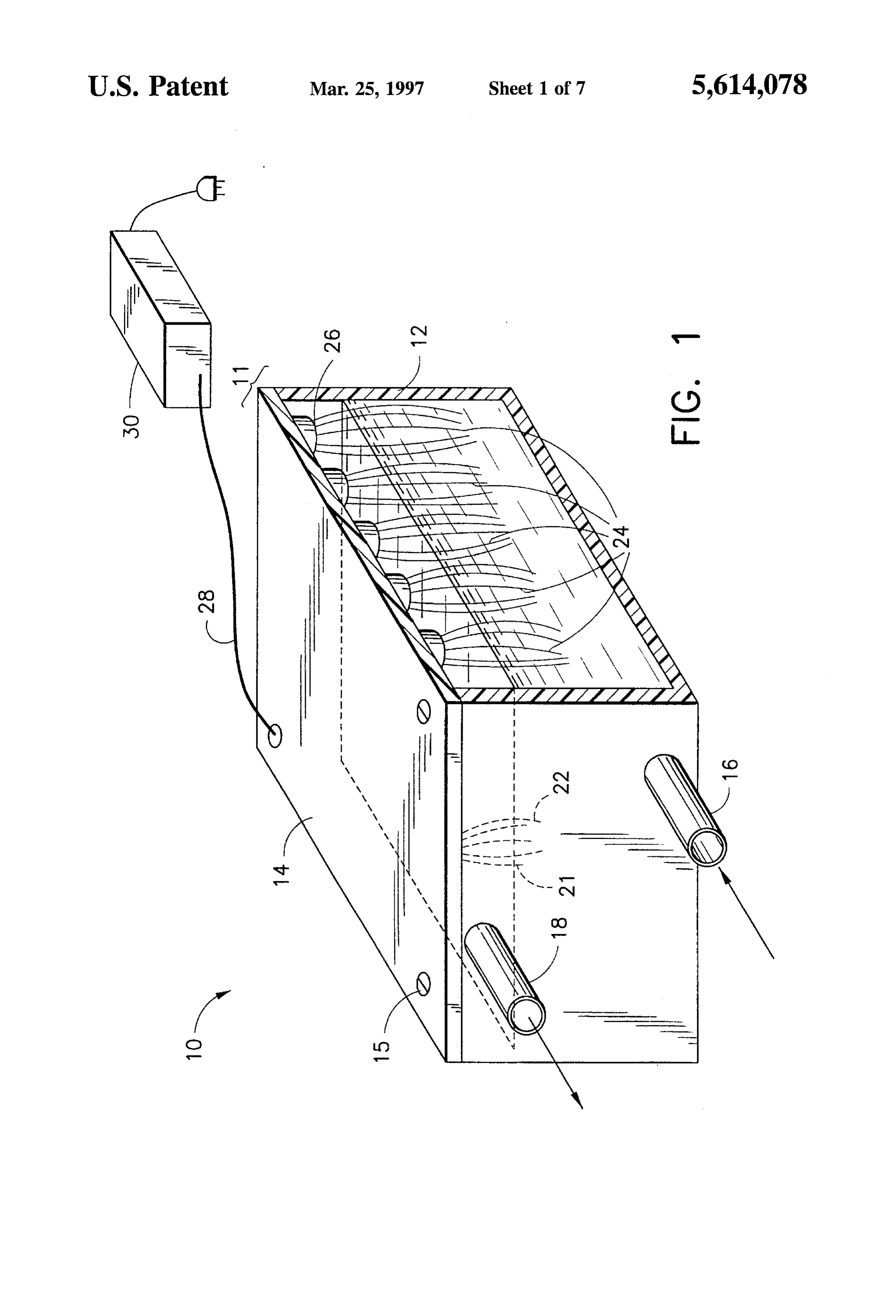
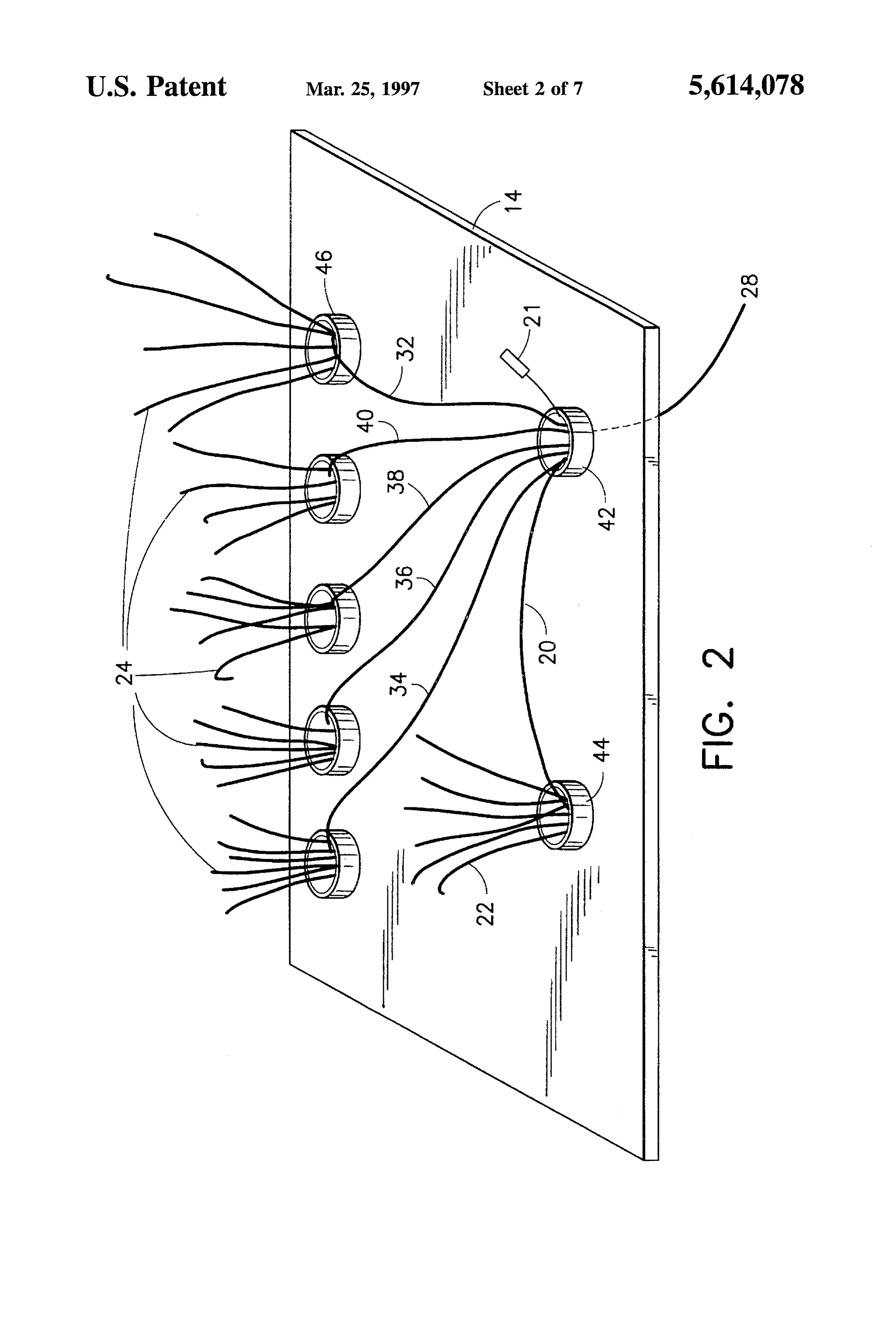
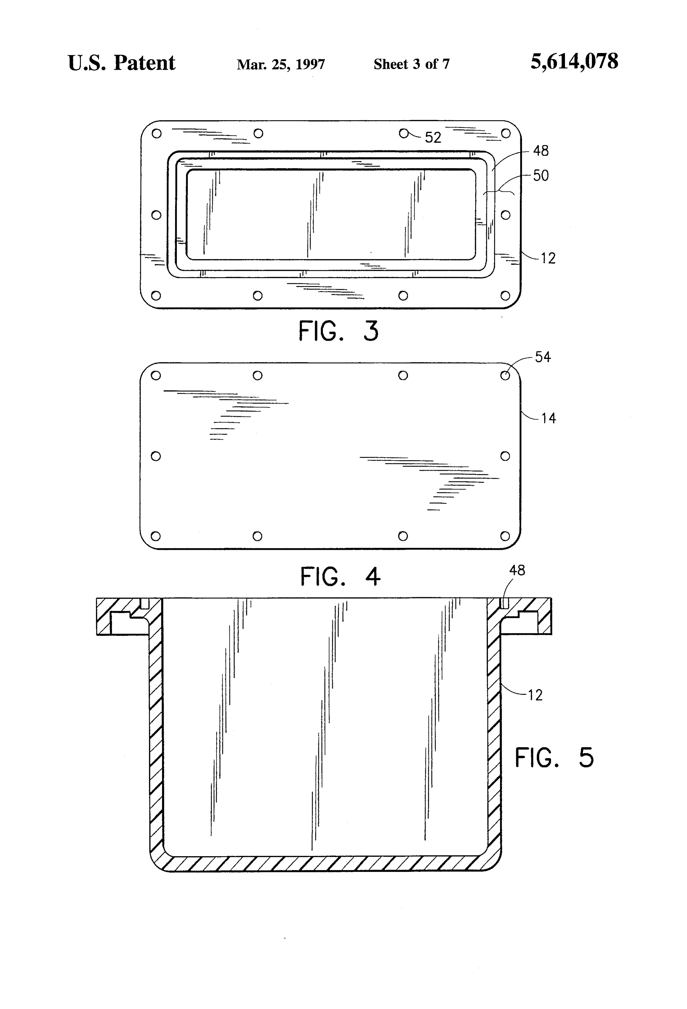
It is still another object of the invention to provide a BRIEF DESCRIPTION OF THE DRAWINGS system which reduces nitrates in water which can be used in batch processing as well as in flow through processing. FIG. 1 is a perspective view of an exemplary embodiment In accord with these objects which will be discussed in 35 of a nitrate reducing apparatus according to the invention; detail below, the apparatus of the present invention generally FIG. 2 is an upside down perspective view of the lid and includes an electrochemical flow cell through which the electrode system of the embodiment of FIG. 1; aqueous solution containing nitrates flows or a holding tank FIG. 3 is a top view of the container portion of the flow cell into which the solution is introduced and then released cell of the embodiment of FIG. 1, after processing, and an electrode system including a carbon 40 FIG. 4 is a top view of the lid portion of the flow cell of fiber cathodic electrode, a carbon fiber anodic electrode and the embodiment of FIG. 1, a reference electrode. All of the electrodes are immersed in the aqueous solution and coupled to an electronic control FIG. 5 is a side sectional view of the container portion of circuit which impresses a voltage across the electrodes such the embodiment of FIG. 1;
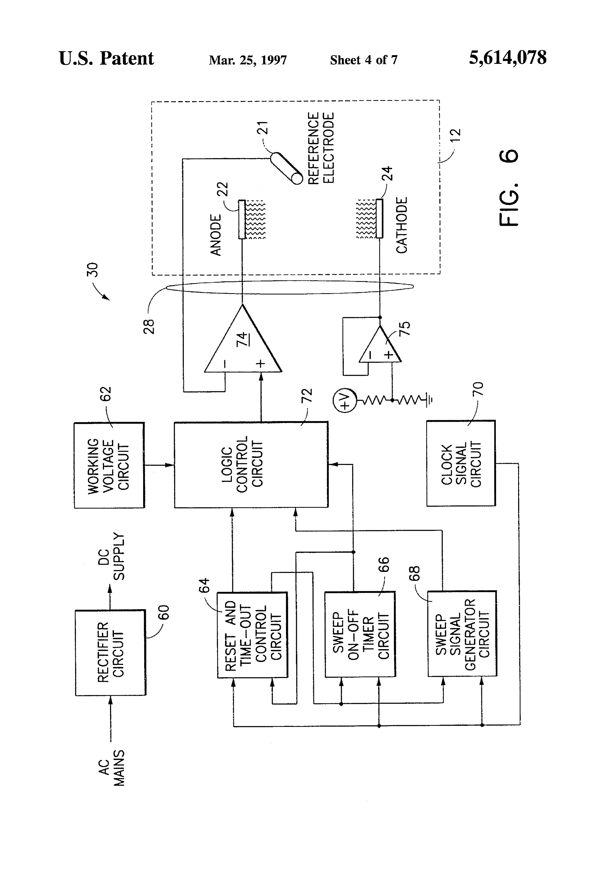
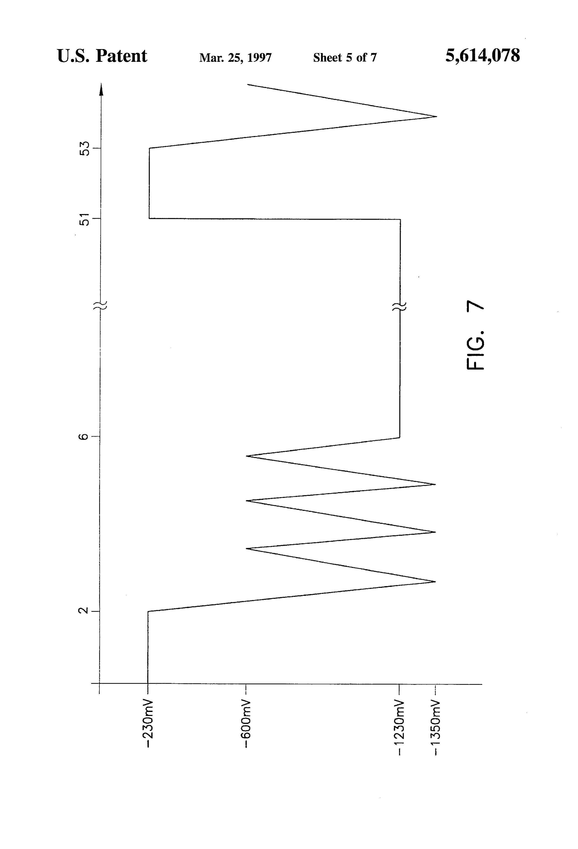
that the voltage causes electrochemical reduction/oxidation 45 FIG. 6 is a schematic block diagram of an exemplary reactions on the surfaces of the cathodic and anodic elec embodiment of an electrical circuit for powering the elec trodes. According to the method of the invention, the elec trodes according to the invention; trodes are at a potential wherein nitrates are reduced to FIG. 7 is a plot of voltage against time illustrating the gaseous products but hydrogen, oxygen, chlorine, and other presently preferred voltage pattern applied to the electrodes noxious substances are not produced. According to the 50 according to the invention;
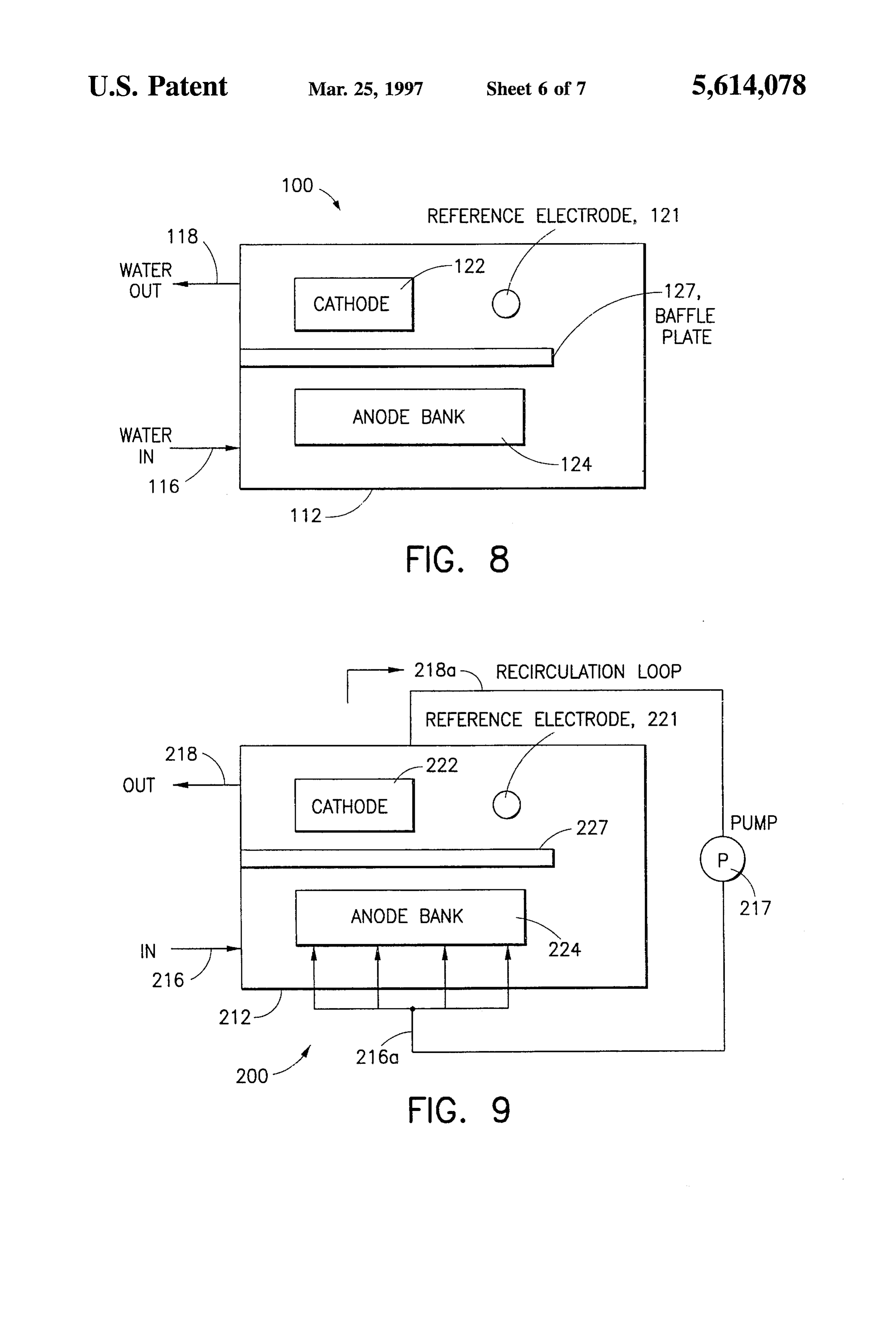
presently preferred embodiment of the invention, the refer FIG. 8 is a schematic plan view of a second embodiment ence electrode is a silver/silver chloride electrode. The flow of the invention;
cell or holding tank is preferably made of an inert material FIG. 9 is a schematic plan view of a third embodiment of which is non-reactive and non-conductive. In smaller sys the invention;
tems inert plastic such as molded polyvinyl chloride, acety 55
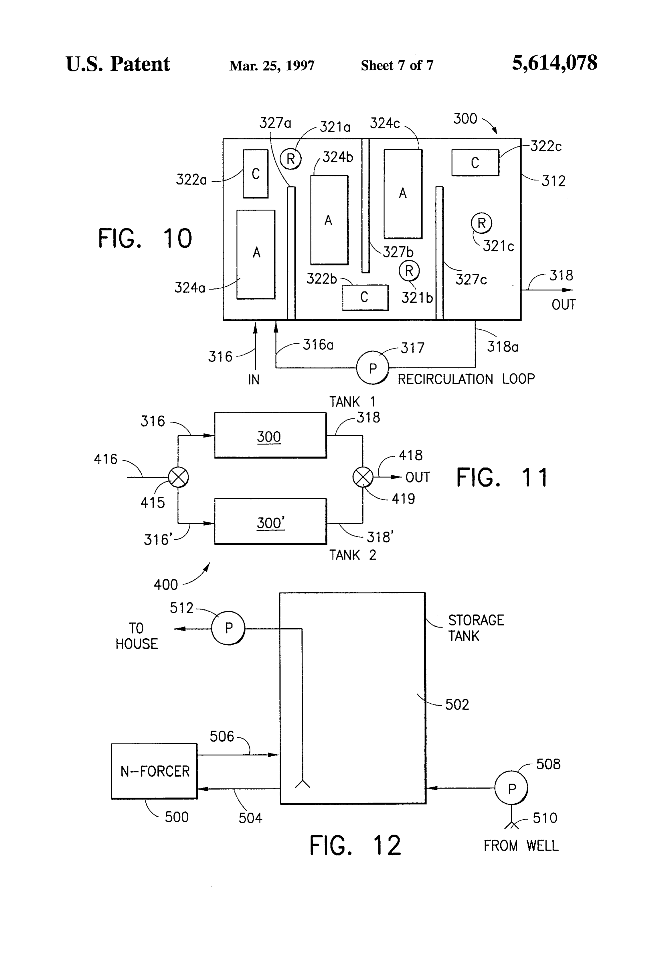
FIG. 10 is a schematic plan view of a fourth embodiment lene butylene styrene, polymethyl methacrylate or polycar of the invention;
bonate are preferred materials. In larger systems various fiberglass, resins or concrete are suitable materials. Accord FIG. 11 is a schematic plan view of a fifth embodiment of ing to a further preferred embodiment, the cathodic and the invention; and anodic electrodes are carbon fibers based on polyacryloni 60 FIG. 12 is a schematic side elevation view of an appli trile (PAN). The surface area ratio of the anodic electrode to cation of the invention coupled to a well water holding tank the cathodic electrode is preferably in the range of 40:1 to for the reduction of nitrates in home drinking water. 120:1. A presently preferred method of energizing the elec EDETALED DESCRIPTION OF THE trodes includes interrupting the working voltage with a brief PREFERRED EMBODIMENTS time-out voltage which is substantially less than the working 65 voltage and following the time-out voltage with a brief Referring initially to FIGS. 1 and 2 of the drawings, in sweep voltage which varies according to a wave function. which like numerals indicate like elements throughout the
Page 12
several views, an exemplary embodiment the nitrate reduc preferably includes a flange 50 and an integral o-ring groove ing apparatus of this invention is generally illustrated by 48. An o-ring or gasket (not shown) of a suitable compress reference numeral 10. The nitrate reducing apparatus 10 ible material is used in the o-ring groove 48 or flat upon the includes a flow cell 11 which includes a container 12 and a flange surface to form the seal between lid 14 and container lid 14, both preferably molded of polystyrene. The lid 14 is 12. In a preferred exemplary embodiment, the container 12 bolted to container 12 by screws 15. The nitrate reducing has the following dimensions: 10.4 inches (length)x8.4 apparatus 10 further includes a solution inlet 16 through the inches (width)X7.0 inches (height). However, it will be side of container 12 and a solution outlet 18 which is spaced understood that nitrate reducing apparatus 10 may be of apart from the solution inlet 16. A reference electrode 21, a various dimensions depending on the application and as cathodic electrode or cathode 22, and an anodic electrode or 10 described below with reference to FIGS. 8-12. The con anode 24, are immersed in an aqueous solution in the tainer 12 also has holes 52 through which lid 14 is bolted. container 12 and coupled to a voltage source as described The lid 14 has holes 54 which are equal in number to holes below when nitrate reducing apparatus 10 is operational. 52 of container 12, for bolting lid 14 to container 12 and the lid 14 has the same dimensions as flange 50.
The anode 24 preferably includes a plurality of anodic In the exemplary embodiment described above, water electrode portions arranged in parallel, so as to provide 15 flows through flow cell 11 at a flow rate preferably in the maximum anodic to cathodic surface area. The cathode 22 range of 50 to 250 gallons per hour. While the nitrate and anode 24 are carbon fiber electrodes, and are preferably reducing apparatus 10 usually requires the lid 14, it is not based on polyacrylonitrile (PAN) although they may also be always necessary to have lid 14. For instance, it is possible carbon fibers based on petroleum derivatives and/or phe to have the electrodes suspended from a bar and immersed nolic resins. To achieve significant nitrate reduction rates, 20 in the aqueous solution. The necessity of lid 14 depends on the surface area of cathode 22 must be large. Carbon fiber the placement of nitrate reducing apparatus 10 relative to the densities ranging from 3k to 320k fibers per tow are com Sump, the sizes of solution inlet 16 and solution outlet 18, mercially available, although the exemplary embodiment and the required flow rate. In the exemplary embodiment, employs a 12k carbon fiber. In the exemplary embodiment, the lid 14 is generally required, because the flow cell 11 is the surface area of cathode 22 is 10 square feet. Given the 25 generally placed at the same level as the sump, and the sizes large surface area to volume ratio of the carbon fibers, the of solution inlet 16 and solution outlet 18 are comparatively total volume occupied by cathode 22 is only approximately small in relation to the desired flow rate of the aqueous 0.125 inches (diameter)X3.5 inches (length) using the 12k solution for achieving maximum nitrate reduction. carbon fiber. To prevent a chlorine evolution reaction from In moderate to large aquariums, water flows from the taking place at anode 24, the anode to cathode surface area 30 aquarium (not shown) to a sump (not shown). From the ratio has to be large, which means low anodic current density Sump, water may be pumped through filtration or chemical for anode 24. In the preferred embodiments, this ratio is treatment chambers, ultraviolet sterilizers, chillers, etc., (not approximately 80:1. The surfaces of cathode 22 and anode shown) depending on the aquarist's particular system. Most 24 may be chemically or electrochemically modified by of these devices are low pressure systems, so that water is known processes. While most of the known processes relate 35 pumped in under pressure, yet it flows out passively in an to non-fiber carbon electrodes, these treatments may also be unrestricted manner, usually back to the sump. In these applied to carbon fiber electrodes. Depending on the char systems, the nitrate reducing apparatus 10 is advantageously acteristics of cathode 22 and anode 24 and the type of placed so that aqueous solutions flow through the flow cell surface treatment used, the surface area ratio is preferably in 11 before returning to the sump.
the range of 5:1 to 15:1. In operation, a method is provided whereby nitrates are The reference electrode 21 is preferably a silver/silver reduced to non-toxic gaseous products such as NO, in an chloride reference electrode.
aqueous solution via an electrochemical reduction reaction
The three electrodes of the nitrate reducing apparatus 10 which occurs at the cathode. In order for current to flow in are connected to an electronic control circuit 30 via a three 45 the aqueous solution, a potential must be established conductor cable 28. The electronic control circuit 30 con between the electrodes. Electrochemical reduction/oxidation trols the voltage pattern and magnitudes applied to the ("redox') reactions occur on electrode surfaces at specific electrodes, which will be more fully described below. electrode potentials. For a given reaction at a given electrode As seen in FIG. 2, all electrical connections within the potential, different electrode materials with the same surface flow cell 11 are preferably encapsulated in non-toxic epoxy 50 area will transfer different quantities of current, i.e. the or similar non-toxic material contained in thin plastic shells current density will vary. Thus, the catalytic properties of the (42, 44, 46) attached to the lid 14. The several sections of materials are different for specific reactions, and therefore anodic electrode 24 are connected in parallel by wires (32, reaction rates will vary per unit electrode surface area. To 34, 36, 38, 40) to one of the conductors of cable 28 at a achieve a given reaction rate per unit surface area, the potting shell 42. The cathodic electrode 22 is connected to 55 required electrode potential is a function of the electrode the second conductor of cable 28 by wire 20 at the potting material. Good catalysts require a lower electrode potential shell 42. The reference electrode 21 is connected directly to (less energy) than poor catalysts. Carbon fibers, and espe the third conductor of cable 28. Those skilled in the art will cially PAN carbon fibers have been discovered to be very appreciate that the electrodes may be mounted and electri good electro-catalysts for nitrate reduction and at a low cally coupled to the power source in other ways which 60 potential. In addition, carbon fibers demonstrate poor elec assure proper electrical insulation and prevent copper con tro-catalytic behavior for hydrogen, oxygen, and chlorine ductors from coming in contact with the aqueous solution. reactions. The low potential required for nitrate reduction For example, by using titanium conductors between the with carbon fibers also helps to prevent any hydrogen, electrodes and copper power conductors, potting can be oxygen, and chlorine reactions.
avoided. 65 Electrochemical nitrate reduction takes place at the cath Referring now to FIGS. 3-5, a top view of the container ode 22. The anodic and cathodic currents are of the same 12 and the lid 14, respectively, are shown. The container 12 absolute magnitude, so that the number and nature of anodic
Page 13
reactions depends on, among other things, the electrolyte voltage of approximately -230 mV is applied for approxi solution (its composition, concentrations of electrolytes, pH, mately two minutes and is followed by a triangular wave etc.), the electrode material and the current density through sweep voltage having a low end of approximately -600 mV anode 24. PAN based carbon fiber electrodes are preferably and a high end of approximately -1350 mV. The sweep used in the nitrate reducing apparatus 10 because, with this voltage is applied for approximately four minutes and is type of material, nitrate may be reduced at a lower electrode followed by a constant working voltage of approximately potential than that required for the hydrogen evolution -1230 mV. The working voltage is applied for approxi reaction, so that hydrogen is not produced and the pH of the mately forty-five minutes after which the cycle begins again. solution does not change appreciably. In general, the effectiveness of nitrate reducing apparatus According to the methods of the invention, a direct 10 10 depends on the flow rate of the aqueous solution, the current or constant working voltage is impressed between volume of the aqueous system, the standing nitrate and the reference electrode 21 and the cathode 22 by the elec biomass concentration in the aqueous system, and the rate of tronic control circuit 30 through cable 28. Nitrate reduction ongoing nitrate loading (i.e. adding food and fish to a marine takes place at this working voltage. Periodically this work system) to the aqueous system.
ing voltage is replaced for a length of time by a "time-out” 15 From the foregoing description those skilled in the art will period voltage. The time-out period voltage is a low constant appreciate that all of the objects of the present invention are level electrode potential at which no nitrate reduction takes realized. An apparatus for removing nitrates from water has place. Its purpose is to serve as a deterrent for the anodic been shown and described which reduces the toxicity of potential to drift into the chlorine evolution range. The time-out period voltage is followed by a sweep voltage, 20 marine and other aqueous systems to living organisms which is a waveform whose upper and lower limits fall without the use of corrosive metals and without the genera above and below the constant working voltage. The wave tion of other poisonous substances. form may be a triangular, square, sawtooth, or other known While an exemplary embodiment has been shown and sweep waveforms. The periodic sweep voltage serves to described, many variations are possible. The device can be clean and resensitize the electrode surfaces. According to the 25 manufactured in different sizes depending on the applica invention, the above signal sequence continues unabated for tion, i.e. a home aquarium versus a commercial/industrial as long as power is available. No adjustments are necessary, water treatment facility. Other applications include various as the process is self-limiting in that current only flows salt water and fresh water environments, swimming pools related to the nitrate concentration. Preferably, all voltages and environmental applications, such as water purification, used with nitrate reducing apparatus 10 in contact with the 30 environmental cleanup and waste water management. FIGS. aqueous solution are less than 5 volts. Eventually, the nitrate 8-12 show several variations of the apparatus according to removal rate will equal its production rate and nitrate levels the invention suitable for several different applications. will be stable and extremely low. Those skilled in the art will appreciate that the dimensions Turning now to FIG. 6, an exemplary control circuit 30 given above provide for a system with a relatively gentle rate generally includes a rectifier circuit 60 which is coupled to 35 of nitrate reduction suitable for relatively small aquaria and that in other applications, the size of the electrodes may be
AC mains and provides a low DC voltage to the other increased in order to provide for more rapid nitrate reduc components of the control circuit 30. Separate functional tion.
blocks are shown in FIG. 6 for a working voltage circuit 62, a reset and time-out control circuit 64, a sweep on-off timer Turning now to FIG. 8, a nitrate reduction apparatus 100 circuit 66, and a sweep signal generator circuit 68. Each of 40 includes a tank 112 having an inlet 116 and an outlet 118. A the circuits 64, 66, and 68 receives a time base signal from baffle plate 127 is placed between the inlet and the outlet and a clock signal circuit 70 and provides an output to a logic an anode bank 124 is placed on the inlet side of the baffle control circuit 72 which also receives an input from the plate. A cathode 122 and reference electrode 121 are placed working voltage circuit 62. The logic control circuit 72 on the outlet side of the baffle plate 127. It will be appre provides an output voltage to the positive input of an 45 ciated that the relative positions of the cathode and reference amplifier 74 which provides a positive voltage to the anode electrode shown in FIG. 8 may be reversed and that the 22 via the three conductor cable 28. The reference electrode direction of water flow may be reversed. The baffle directs 21 is electrically coupled to the negative input of the the flow of water over the electrodes to provide a more amplifier 74 via the three conductor cable 28, and the efficient nitrate removal.
cathode 24 is coupled via the three conductor cable 28 to an 50 FIG. 9 shows an apparatus 200 which is similar to the amplifier 75 such that its potential bias is maintained. apparatus 100 shown in FIG. 8 and where similar reference As mentioned above, when the circuit 30 is energized, the numerals refer to similar features. The apparatus 200 voltage applied to the electrodes is varied over time. In the includes an additional inlet 216a and an additional outlet preferred exemplary embodiment, the working voltage is in 218a which are coupled to each other by a recirculating the range of -1,000 mV to -1,300 mV versus reference 55 conduit and pump 217. The recirculation of water inside the electrode 21 for a period of time in the range of approxi tank 212 improves the efficiency of nitrate removal and mately 5 to 45 minutes. The time-out period voltage is allows for faster effective throughput through the system via preferably in the range of -100 mV to -300 mV versus the inlet 216 and the outlet 218. reference electrode 21 for a period of time in the range of FIG. 10 shows a very high volume embodiment which approximately 1 to 20 minutes. A low end of the sweep 60 builds on the features of embodiments 100 and 200. The voltage is preferably in the range of -400 mV to -700 mV apparatus 300 shown in FIG. 10 includes a tank 312 having versus reference electrode 21, and a high end of the sweep an inlet 316 and an outlet 318. A plurality of baffle plates voltage is preferably in the range of -1,000 mV to -1,400 327a-c are arranged in a labyrinth between the inlet and mV versus reference electrode 21. The sweep voltage cycle outlet. A corresponding plurality of anode banks 324a-c, preferably lasts for a time period in the range of approxi 65 cathodes 322a-c, and reference electrodes 321a-c are mately 1 to 24 minutes. FIG. 7 shows an example of the arranged between the baffle plates. In addition, a recirculat output of the circuit 30. As shown in FIG. 7, a time-out ing outlet 318a and a recirculating inlet 316a are coupled to
Page 14
each other by a fluid conduit and a recirculating pump 317. the same or similar function as disclosed herein depending It will be appreciated that the baffle arrangement and the on the scale of the system and the size of the electrodes. electrode arrangement are such that water entering the inlet It will therefore be appreciated by those skilled in the art 316 is subjected to several reactions as it passes through the that yet other modifications could be made to the provided labyrinth to the outlet 318. In addition, water is recirculated invention without deviating from its spirit and scope as so from the outlet to the inlet for further processing. This type claimed.
of arrangement can be scaled to process water at the rate of We claim:
one thousand gallons per minute or more, i.e. over one 1. An apparatus for reducing nitrates in an aqueous million gallons per day. Solution, comprising:
FIG. 11 shows still another high volume apparatus 400 O a) an electrochemical cell in which the aqueous solution according to the invention. The apparatus 400 actually containing nitrates is treated, said cell comprising a includes two of the apparatus 300,300' described above with container;
the inlets 316, 316' coupled through a two-way valve 415 to b) an electrode system including a carbon fiber cathodic the inlet 416 of the apparatus 400 and the outlets 318, 318' electrode, a carbon fiber anodic electrode, and a refer coupled through a two-way valve 419 to the outlet 418 of the 15 ence electrode, wherein all of said electrodes are apparatus 400. In use, the valves 415, 419 are set so that the immersed in the aqueous solution; and first tank 300 is filled, then switched so that the second tank 300' is filled. By the time the second tank 300' is filled, the c) an electronic control circuit including a means for processing of the water in the tank 300 is substantially impressing a voltage across said electrodes causing electrochemical reduction/oxidation reactions on the complete and the valves are switched again. The valves may 20 Surfaces of said cathodic and anodic electrodes, and be operated automatically based on time and water flow rate. means for controlling said electrodes at a potential The apparatus 400 can produce a processing throughput wherein nitrates are reduced to gaseous products, and double that of the apparatus 300. further wherein hydrogen, oxygen and chlorine are not As mentioned above, the electrical requirements of the produced.
apparatus of the invention are modest and the apparatus is 25 2. An apparatus according to claim 1, wherein: therefore energy efficient and may be run continuously. In said cell is a flow cell through which the aqueous solution the exemplary embodiment described above with reference flows.
to FIGS. 1-5, a system processing about 400 gallons per 3. An apparatus according to claim 2, wherein: hour will consume approximately 1 to 10 watts. In the larger said flow cell further comprises a lid and said electrodes systems which process water at rates of 1,000 gallons per 30 are attached to said lid.
minute or more, power consumption is on the order of 25 to 4. An apparatus according to claim 1, wherein: 100 Kilowatts.
While the invention has thus far been described with said cell is molded of materials selected from the group consisting of polyvinyl chloride, acetylene butylene reference to aquatic Systems and large industrial waste styrene, polymethyl methacrylate, and polycarbonate. cleanups, the apparatus has a valuable application in home 35 5. An apparatus according to claim 1, wherein: use where well water may be contaminated with nitrates. said container includes a flange and an o-ring groove FIG. 12 shows how an apparatus 500 according to the integral with said flange. invention can be coupled to a well water holding tank 502 6. An apparatus according to claim 1, wherein: via recirculation conduits 504, 506. In normal use, well water is drawn by a pump 508 from a well 510 and stored 40 7. Anreference said apparatus electrode is silver/silver chloride.
according to claim 1, wherein:
in a holding tank 502 until it is drawn out of the tank via interior plumbing 512 for household use. Typically, the the materials of which said cathodic and anodic electrodes water resides in the tank 502 for several hours before it is are made are carbon fibers based on material selected used in the home. While water is held in the tank 502, the from the group consisting of polyacrylonitrile, petro apparatus 500 according to the invention treats the water to 45 leum derivatives and phenolic resins. reduce nitrate concentration so that water supplied to the 8. An apparatus according to claim 7, wherein: interior plumbing 512 is safe to drink. the surface area of said cathodic electrode is approxi There have been described and illustrated herein several mately 10 square feet.
embodiments of a method and apparatus for reducing nitrate 9. An apparatus according to claim 7, wherein: concentration in water. While particular embodiments of the 50 said cathodic and anodic electrodes are based on the same invention have been described, it is not intended that the material.
invention be limited thereto, as it is intended that the 10. An apparatus according to claim 9, wherein: invention be as broad in scope as the art will allow and that the anodic electrode to cathodic electrode surface area the specification be read likewise. Thus, while particular ratio is in the range of 40:1 to 120:1. materials have been disclosed for constructing the flow cell 55 11. An apparatus according to claim 9, wherein: or holding tank, it will be appreciated that other non the surfaces of said cathodic and anodic electrodes are reactive, nonconductive materials could be utilized. Also, chemically modified.
while particular dimensions have been shown with respect to 12. An apparatus according to claim 11, wherein: the exemplary embodiment, it will be recognized that other the anodic electrode to cathodic electrode surface area dimensions would be used with similar results obtained in 60 systems of different scale. Moreover, while particular con ratio is approximately is in the range of 5:1 to 15:1. figurations have been disclosed in reference to the electrical 13. An apparatus according to claim 9, wherein: control circuit, it will be appreciated that other configura the surfaces of said cathodic and anodic electrodes are tions providing similar functional signals could be used as electrochemically modified. well. Furthermore, while some embodiments have been 65 14. An apparatus according to claim 13, wherein: disclosed as having a certain number of electrodes, it will be the anodic electrode to cathodic electrode surface area understood that different numbers of electrodes can achieve ratio is approximately is in the range of 5:1 to 15:1.
Page 15
15. An apparatus according to claim 1, wherein: 17. A method according to claim 16, wherein: said electronic control circuit further comprises means for said step of providing a cell comprises providing a flow sequentially providing three voltage signals between cell, and said reference electrode and said cathodic electrode, 5 said step of introducing comprises pumping the solution wherein each of said voltage signals are of different through the flow cell.
magnitudes, said voltage signals being a constant time 18. A method according to claim 17, wherein: out period voltage, a sweep voltage and a constant the flow rate of the aqueous solution through said flow cell working voltage. is in the range of 50 to 250 gallons per hour. 16. A method of reducing nitrates in an aqueous solution, 10 19. A method according to claim 16, wherein: comprising the steps of: said step of impressing comprises sequentially impressing three voltage signals between the reference electrode a) providing an electrochemical cell including a container and the cathodic electrode, wherein each of the voltage for at least partially containing the solution; signals are of different magnitudes, the voltage signals b) providing an electrode system including a carbon fiber being a constant timeout period voltage, a sweep volt cathodic electrode, a carbon fiber anodic electrode, and 15 age and a constant working voltage. a reference electrodc; 20. A method according to claim 19, wherein: c) arranging all of the electrodes in the container such that said time-out period voltage is in the range of -100 mV to -300 mV versus said reference electrode.
they can be submersed in the solution when the solution 21. A method according to claim 19, wherein: is introduced into the container, 20 a low end of said sweep voltage is in the range of -400 d) introducing the solution into the cell such that all of the mV to -700 mV versus said reference electrode and a electrodes are immersed in the aqueous solution; high end of said sweep voltage is in the range of -1,000 e) providing an electronic control circuit operably con mV to -1,400 mV versus said reference electrode. nected to the electrodes which controls the potential at 25 22. A method according to claim 19, wherein: the electrodes; and said working voltage is in the range of -1,000 mV to f) impressing a voltage across the electrodes, the voltage -1,300 mV versus said reference electrode. causing an electrochemical reduction/oxidation reac 23. A method according to claim 19, wherein: tion on the surfaces of the cathodic and anodic elec no nitrate reduction occurs during the period of said trodes, wherein nitrates are reduced to gaseous prod time-out period voltage.
ucts at the cathodic electrode and wherein hydrogen, 30 oxygen and chlorine are not produced.
Provenance
- Collection
- Cited prior art
- Original PDF
- patentimages.storage.googleapis.com →
- Filed
- 1996-06-26
- Pages
- 15
- Method
- pdftotext (the PDF's own text layer) + pdftoppm 300dpi page scans
- Source
- Google Patents bibliographic record
- Granted
- 1997-03-25
- Inventors
- Mark Lubin; Sjef Otten; Upscale Technologies Inc
- Transcribed from
- patentimages.storage.googleapis.com →