patent · US4376423
Method and apparatus for saturating a liquid fuel with a gas and an internal combustion engine
15 March 1983
Page 1 — bibliographic record
United States Patent (19) 11) 4,376,423 Knapstein (45) Mar. 15, 1983 (54) METHOD AND APPARATUS FOR FOREIGN PATENT DOCUMENTS
SATURATING ALIQUID FUEL WITH A GAS
AND AN INTERNAL COMBUSTION ENGINE 897181 3/1945 France ................................ 123/. A
(75) Inventor: Paul E. Knapstein, Lake Wales, Fla. Primary Examiner-Wendell E. Burns Attorney, Agent, or Firm-William M. Hobby, III (73) Assignees: William C. Knapstein; Carol A. (57) ABSTRACT Knapstein, both of Vero Beach, Fla.
An apparatus and a method of saturating liquid fuel (21) Appl. No.: 271,363 with air, oxygen, or another gas for injecting into an internal combustion engine. The internal combustion (22) Filed: Jun. 8, 1981 engine is provided with a gas compressor or pump for (51) int. Cli............................................. FO2M 43/00 compressing air or oxygen, which is directed into a fuel (52) U.S.C. .................................... 123/1 A; 123/523; saturator having a dense, porous material or stone 123/533; 123/585; 123/304; 123/3 therein and having a liquid hydrocarbon fuel being fed 58 Field of Search ............... 123/523, 585, 304, 533, therethrough. Compressed gas is fed onto one side of 123/531, 1 A, 3, 575 the stone and is forced therethrough for saturation into the liquid fuel, which is then fed into a fuel injection (56) References Cited system of an internal combustion engine. Gas that sepa
moved therefrom. The fuel saturator uses a gas satura 2,965,085 12/1960 Kahler ............................ 123/1 AX tion stone, which may be hollow in one end for feeding 3,828,736 8/1974 Koch . ....... 123/3 a compressed gas thereinto, while the other side is sur 3,877,450 4/1975 Meeks ............... ... 123/1 AX rounded with the liquid hydrocarbon fuel. The liquid 3,977,365 8/1976 Vierling et al... ...... 123/1 A hydrocarbon fuel may be fed around a spiralling pas 401,840 3/1977 Forster .................................... 23/3 sageway adjacent the stone for a more complete satura 4,068,639 1/1978 Cook ......... ... 123/1 A tion of the fuel.
4,161,160 7/1979 Hicks et al. .. ... 123/1 A 4,167,920 9/1979 Lepera ................................ 123/1 A 4,331,121 5/1982 Stokes ................................. 123/575 25 Claims, 2 Drawing Figures
Page 2
Drawing sheet — no readable text.
Page 3
SUMMARY OF THE INVENTION
METHOD AND APPARATUS FOR SATURATINGA
LIQUID FUEL WITH A GAS AND AN INTERNAL An internal combustion engine is provided having a COMBUSTON ENGINE gas saturator for saturating liquid fuels with a gas such as air or oxygen. The internal combustion engine has a
BACKGROUND OF THE INVENTION gas saturation means for saturating gas into a liquid fuel. The gas saturation means has a liquid fuel inlet or input
The present invention relates to internal combustion and a liquid fuel output, as well as a gas inlet, and in engines, and especially to fuel injection type engines in cludes a container having a dense, porous material such which the liquid fuel has been saturated with a gas for 10 as special types of natural stone. The liquid fuel is fed injection into the engine. over one side of the stone, while the gas under pressure In the past, a great variety of internal combustion is fed to the other. A gas compressor is provided for engine fuel systems have been provided for use on inter compressing the gas, and the gas compressor is con nal combustion engines in vehicles and for other pur nected to the gas saturation means gas inlet for directing poses. Typically, a hydrocarbon fueled engine might 15 the gas under pressure to the gas saturation means. have a carburetor in which a liquid fuel is vaporized in Means are provided for directing the liquid fuel satu a fixed or variable venturi as air from the atmosphere is rated with the gas from the gas saturation means into fed through the venturi, drawing liquid vapor into the the internal combustion engine combustion chambers. intake manifold and into the cylinders of the engine. A gas bleed off is provided to capture gas that escapes Diesel engines more commonly provide a fuel injection 20 from the saturated liquid fuel and to feed the gas to a system in which the fuel is injected directly into the fuel trap for capturing vapor pulled off with the gas, combustions chambers under high pressure and does internal The method of saturating a liquid fuel with gas in an not use a spark to ignite the charge being injected into combustion engine is also provided comprising the cylinder. Typically, air has already been drawn into 25 the steps of compressing the gas, applying the com the cylinder and compressed at the time the fuel is in pressed gas against one side of a dense, porous material, jected thereinto. It is also common to provide a fuel or stone and passing a liquid fuel under pressure against injection system for more conventional spark ignition the the other side of the dense, porous material for saturat internal combustion engines which work at a lower ing injecting liquid with the gas forced through the stone, and the gas saturated liquid fuel into the combus combustion chamber pressure in order to improve the 30 tion chambers of the internal combustion engine. Addi efficiency of the engine. tional steps include trapping gas released from the satu The present invention is directed primarily at internal rated liquid and removing vapor from the released gas, combustion engines, both diesel and spark ignited en The fuel saturator includes a dense, porous material gines, which have fuel injection systems and provides mounted in a container and may include a spiralling for the saturation of the liquid hydrocarbon fuel with 35 passageway between the walls of the container and the oxygen or air under pressure through a fuel saturator. dense, porous material to direct the liquid fuel passing The fuel saturator requires a dense, but slightly porous therethrough in a spiralling pattern to assure that the stone or other material which forces a gas under pres fuel gets saturated prior to being injected into the com sure into the liquid fuel. It has been common in the past bustion chambers of the engine.
to saturate liquids with gases, such as carbon dioxide, to BRIEF DESCRIPTION OF THE DRAWINGS form soda water or to increase the gas content in malt drinks, such as beer. Saturated liquids, however, have to Other objects, features and advantages of the present be maintained under pressure until just prior to use. The invention will be apparent from the written description present invention utilizes a stone similar to the one used and the drawings, in which:
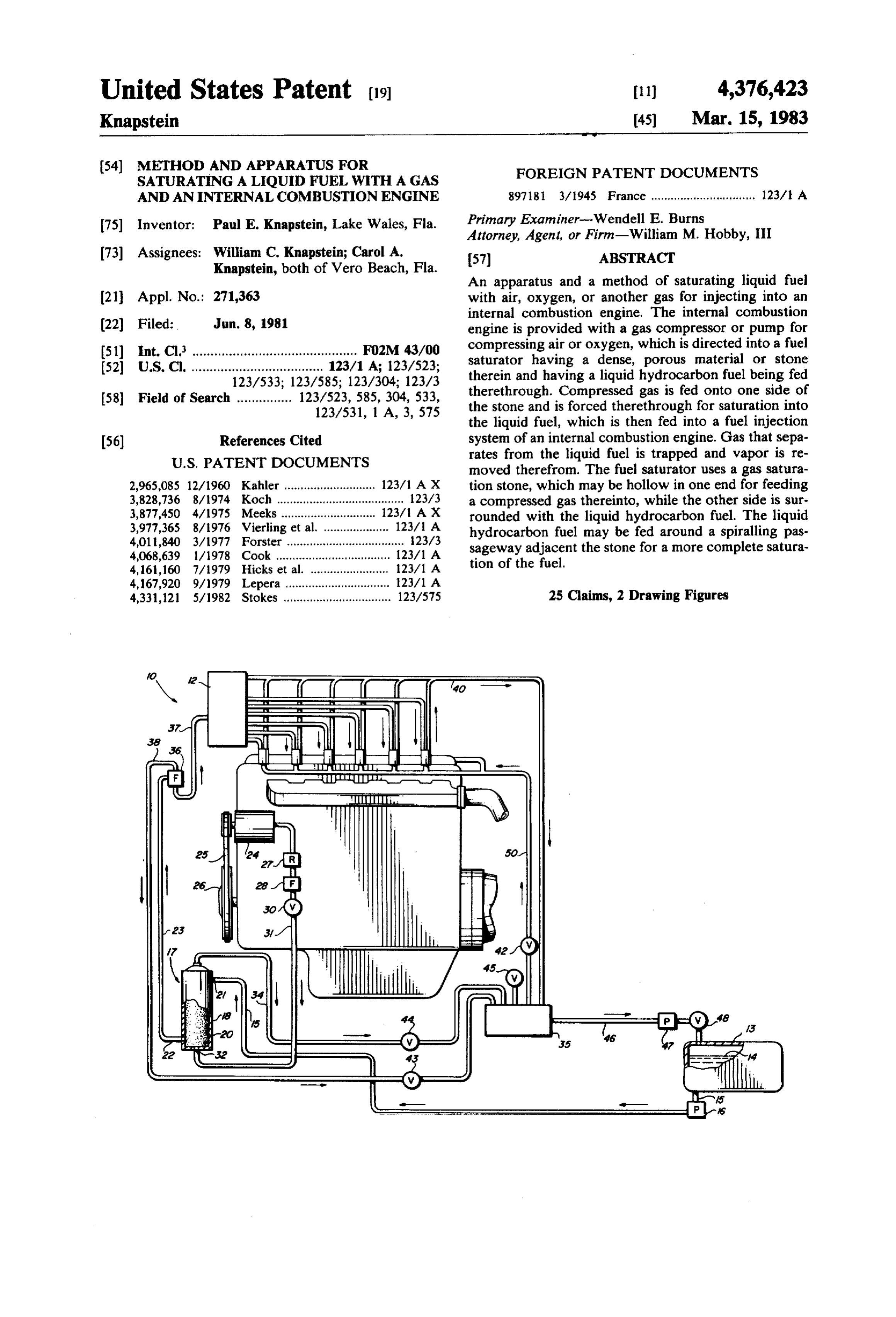
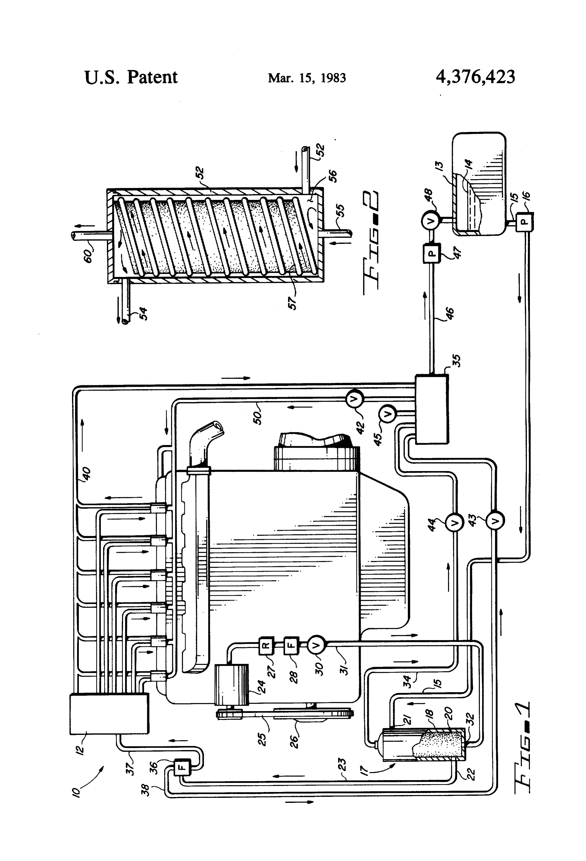
by brewers, but which has been enclosed in a casing 45 FIG. 1 is a diagrammatic view of a fuel system at with a spiralling passageway in order to increase the tached to an internal combustion engine; and FIG. 2 is a sectional view of a fuel saturator for use in rate and saturation of the liquid fuel with a gas.
Other prior art type systems include the use of vari accordance with the present invention. ous systems for bubbling air through a liquid fuel in 50 DESCRIPTION OF THE PREFERRED order to vaporize the fuel, as well as a variety of other EMBODMENTS circuits directed primarily at vaporizing the fuel by the Referring now to the drawings and especially to FIG. passing of a gas therethrough. These systems do not 1, an internal combustion engine 10 is illustrated having attempt to saturate the liquid with a gas, but rather to a plurality of fuel injectors 11 attached thereto and vaporize the liquid in the air, and are used primarily in 55 being connected to a fuel injector pump 12. The fuel carburetor type fuel systems. It has also been known to injectors 11 are the conventional type used on a diesel feed gases into a carburetor at the same time the hydro or spark ignited internal combustion engine, and along carbon fuel is being vaporized therein and various fuel with the pump 12, would not have to be changed in additives have been added to fuels to modify the fuel adapting the present invention to an existing engine, being fed to the fuel system. An advantage of the pres The engine 10 is operated on a liquid fuel such as a No. ent invention is that the hydrocarbon liquid fuel can be 2 diesel fuel or other liquid hydrocarbon fuel, from the saturated with a number of gases which can then be tank 13 having the fuel 14 therein. The fuel 14 is fed used on a fuel injection system without the individual from the tank 13 through a fuel line 15 through a con injectors being broken by air or another gas getting into ventional fuel pump 16 and into the newly added fuel the fuel injectors. That is, most fuel injectors on internal 65 saturator 17. The saturator 17 has a casing 18 and inside combustion engines will not operate if air gets trapped the casing is a dense, porous material 20, such as a in the injectors, so that gases cannot normally be fed brewer stone, which is shown in a cylindrical shape, but with a fuel through a fuel injected system of an engine. which is hollow. The fuel is fed through line 15 into an
Page 4
input 21 and into the container 18. The fuel flows into fed through a gas inlet 55 into a hollow space 56 located the container around the stone 20 and out of outlet 22 in a dense, porous material, such as a brewer stone, into a fuel line 23. An air pump or air compressor 24 which is shaped in a cylindrical shape with a limited attached to the internal combustion engine 10 may be amount of space between the stone 57 and the walls 52 driven by a belt 25 attached to a pulley 26 connected to of the fuel saturator. The stone is then wrapped with a the crank shaft of the engine. Air from the atmosphere spiralling guide 57 which may be adhesively attached to can be compressed in a compressor 24 and is fed the stone or to the interior walls of the casing 52 and through an air regulator 27 through an air filter 28 and which may be of a rubber or polymer material. This through an air check valve 30, through an air line 31 forces the fuel from the fuel inlet 53 around the stone in into fuel saturator 17 inlet 32 and into the inside of the O a spiralling pattern to assure a more complete saturation dense, porous material 20. Under pressure, the air is of the liquid fuel with the gas being fed in the inlet 55. forced through the dense, porous material where it is An outlet 60 allows a bleed off of excess gas from the forced into a liquid fuel therein on the opposite side of liquid fuel which is fed back to the vapor trap 35 of the porous material 20 to saturate the liquid fuel with FIG. 1. It should be clear that a method and apparatus the gas. It should be pointed out at this point, that while 15 for saturating a liquid hydrocarbon fuel with various air is shown being compressed, oxygen or any other gas gases has been provided for use in fuel injection engines. could be saturated into the liquid fuel and rather than a The first tests have utilized a brewer stone as a dense, compressor 24, a small tank of compressed oxygen porous material and this stone is a naturally occurring could be utilized without departing from the spirit and stone, but it should be clear that other dense, porous scope of the invention. materials are also contemplated as being within the The fuel saturator 17 has an outlet 33 from the top scope of the present invention. Accordingly, the pres thereof and in line 34 attached thereto for capturing ent invention is not to be construed as limited to the excess gas being forced into the liquid in the fuel satura forms shown, which are considered to be illustrative tor 17. This gas is fed through the line 34 into a fuel trap rather than restrictive.
35, which may include a foam trap for capturing vapor 25 I claim:
in the gas being removed from the fuel saturator 17. 1. An internal combustion engine having a gas satura Saturated fuel is fed from the fuel filter 36 through a fuel tor for saturating liquid fuel with a gas, comprising in line 37 to the fuel injection pump 12. The fuel filter 36 combination:
also has a gas line 38 connected thereto for removing an internal combustion engine; any additional gas that has escaped from the saturated a gas saturation means for saturating gas into a liquid liquid fuel, which gas is also fed back to the fuel trap 35 fuel and having a liquid fuel inlet and a liquid fuel where fuel vapor is captured in the fuel trap. The satu outlet and a gas inlet;
rated fuel fed through the line 37 into the injector pump gas compressor means for compressing a gas, said gas is injected into the fuel injectors in a conventional man compressor means being connected to said gas ner, except that an additional fuel bleed off line 40 is 35 saturation means gas inlet for directing gas under connected to each fuel injector and each fuel bleed off pressure into said gas saturation means; and line is connected to a fuel bleed off return line 41, which means for directing a liquid fuel saturated with gas is in turn connected to the fuel trap 35. from said gas saturation means into said internal An in-line check valve 43 is connected in the vapor combustion engine combustion chambers whereby return line 38 and a sinilar check valve 44 is connected a liquid fuel saturated with a gas is burned in an in the vapor return line 34. The fuel trap 35 also has a internal combustion engine. pressure relief valve 45 attached thereto to prevent the 2. An apparatus in accordance with claim 1, in which build up of excess pressure therein. The fuel trap has an the gas saturation means includes a dense, porous mate exit liquid fuel line 46 passing through an electric fuel rial for feeding a liquid fuel on one side thereof and a pump 47 and through a check valve 48 back into the 45 compressed gas on the other side thereof for saturating fuel tank 13. The fuel trap 35 has a gas or air line 50 said liquid fuel with said gas.
connected therefrom through the check valve 42 back 3. An apparatus in accordance with claim 2, in which to the air inlet for each combustion chamber for utiliz said gas saturation means has a gas bleed off for bleed ing the gas being returned from the fuel trap 35, which ing off excess gas from said gas saturator. gas may still have a small amount of vapor therein. The SO 4. An apparatus in accordance with claim 3, in which saturated fuel being fed to the combustion chambers said gas compressor means includes an air pump con improves combustion and can enhance the combustion nected to an air regulator to said fuel saturator. process by the use of gases other than air, which would 5. An apparatus in accordance with claim 3, in which further enhance the combustion process. said gas bleed off is fed through to a fuel trap for captur The method of the present invention provides for 55 ing vapor in said gas being bled from said fuel saturator. feeding a liquid fuel to the fuel saturator 17, compress 6. An apparatus in accordance with claim 5, in which ing air or another gas in the compressor 24 and feeding said bleed offline includes an in-line check valve therein it into the fuel saturator 17 on one side of the dense, to prevent gas under pressure from being fed from said porous stone 20, while the fuel is being fed on the other fuel trap back to said fuel saturator. side thereof. The liquid fuel is saturated with the gas 7. An apparatus in accordance with claim 6, in which and then injected into the engine, and might also in said fuel trap includes a foamed polymer material clude the steps of bleeding off excess gas release from therein for capturing liquid fuel therein and a fuel line the saturated fuel and trapping the vapor from the bled connecting said fuel trap to said fuel tank. off gas in a fuel vapor trap. 8. An apparatus in accordance with claim 7, in which FIG. 2 shows a modified embodiment of the fuel 65 said line connecting said fuel trap to said fuel tank has a saturator 51 having a casing 52 and a fuel inlet 53 for fuel pump and a check valve located therein. feeding a liquid fuel thereinto. A fuel outlet 54 feeds fuel 9. An apparatus in accordance with claim 8, in which saturated with gas from the fuel saturator 51. The gas is liquid fuel saturated with gas being fed from said fuel
Page 5
saturator passes through a fuel filter having a gas bleed 18. In an internal combustion engine, a method for offline attached thereto for bleeding off gas to said fuel saturating liquid fuel with gas, comprising the steps of: trap. compressing a gas;
10. An apparatus in accordance with claim 9, in 5 applying said compressed gas against one side of a dense, porous material;
which said bleed offline from said fuel filter has a check passing a liquid fuel under pressure against the other valve therein. side of said dense, porous material for saturating 11. The apparatus in accordance with claim 10, in said liquid fuel with gas through said dense, porous which said fuel from said fuel filter is fed into a fuel material; and injector pump for injection into the engine combustion O injecting said gas saturated liquid fuel into the com chambers and each fuel injector line has a fuel bleed off bustion chamber of an internal combustion engine. return line connected to said fuel trap. 19. The method in accordance with claim 18, includ 12. The apparatus in accordance with claim 5, in ing thefuel. step of trapping gas released from said saturated which said fuel trap has a pressure relief valve attached 15 liquid 20. The method in accordance with claim 19, includ thereto. ing the step of trapping vapor from said gas released 13. The apparatus in accordance with claim 12, in from said saturated liquid in a vapor trap. which said fuel trap has a line connected therefrom into 21. The method in accordance with claim 20, includ the intake air line of said internal combustion engine. ing feeding released gas passing through said vapor trap 14. The apparatus in accordance with claim 13, in 20 back to the engine air intake.
which said gas line from said fuel trap to said intake air 22. The method in accordance with claim 18, in line has a check valve therein. which the step of passing a liquid fuel under pressure 15. An apparatus in accordance with claim 1, in against the other side of a dense, porous material in which said fuel saturator has a cylindrical dense, porous cludes passing the liquid fuel adjacent said stone in a material therein having a spiralling fuel guide formed 25 spiralling
pattern around said dense, porous material.
method in accordance with claim 22, in therearound for directing liquid fuel around said dense, which the step of compressing a gas includes compress porous material in a spiralling passageway. ing atmospheric air in an air compressor. 16. An apparatus in accordance with claim 1, in 24. The method in accordance with claim 18, in which said gas compressor means includes an air pump 30 which the step of compressing includes storing the com connected to an air regulator to said fuel saturator. pressed gas in a cylinder.
17. An apparatus in accordance with claim 16, in 25. The method in accordance with claim 24, in which said gas compressor means is an air pump con which the step of compressing gas includes compressing nected to said fuel saturator through an air filter and an oxygen into a compressed oxygen cylinder.
air check valve. 35
Provenance
- Collection
- Cited prior art
- Original PDF
- patentimages.storage.googleapis.com →
- Filed
- 1981-06-08
- Pages
- 5
- Method
- pdftotext (the PDF's own text layer) + pdftoppm 300dpi page scans
- Source
- Google Patents bibliographic record
- Granted
- 1983-03-15
- Inventors
- Paul E. Knapstein
- Transcribed from
- patentimages.storage.googleapis.com →