patent · US20080296171A1
Multi-cell dual voltage electrolysis apparatus and method of using same
4 December 2008
Page 1 — bibliographic record
(19) United States (12) Patent Application Publication (10) Pub. No.: US 2008/0296.171 A1
Davidson (43) Pub. Date: Dec. 4, 2008 (54) MULT-CELLDUAL VOLTAGE Publication Classification
ELECTROLYSIS APPARATUS AND METHOD
OF USING SAME (51) Int. Cl.
(75) Inventor: Nehemia Davidson, Rosh-Haavin C25B I5/04 (2006.01) (IL) C25B II/04 (2006.01)
(52) U.S. Cl. ...................... 205/639; 204/253; 204/229.4:
Correspondence Address: 205/637; 205/335 PATENT LAW OFFICE OF DAVID G. BECK (57) ABSTRACT
MILL VALLEY, CA 94.942 (US) A method and apparatus for achieving high output efficiency from an electrolysis system (100) using a plurality of elec trolysis cells all located within a single electrolysis tank (101) (73) Assignee: Kuzo Holding Inc., Christ Church is provided. Each individual electrolysis cell includes a mem (BB) brane (105-107), a plurality of low voltage electrodes com prised of at least a first and second anode (117/118: 125/126) (21) Appl. No.: 12/151,331 and at least a first and second cathode (121/122; 129/130), and a plurality of high Voltage electrodes comprised of at least
(22) Filed: May 6, 2008 cell, the high voltage anode is interposed between the first and second low Voltage anodes and the high Voltage cathode is interposed between the first and second low voltage cathodes.
(30) Foreign Application Priority Data The low voltage applied to the low voltage electrodes and the high Voltage applied to the high Voltage electrodes is pulsed
May 30, 2007 (CA) .................................... 2,590,487 with the pulses occurring simultaneously.
PULSE
GENERATOR
Page 2
Drawing sheet — no readable text.
Page 3
Drawing sheet — no readable text.
Page 4
Drawing sheet — no readable text.
Page 5
Drawing sheet — no readable text.
Page 6
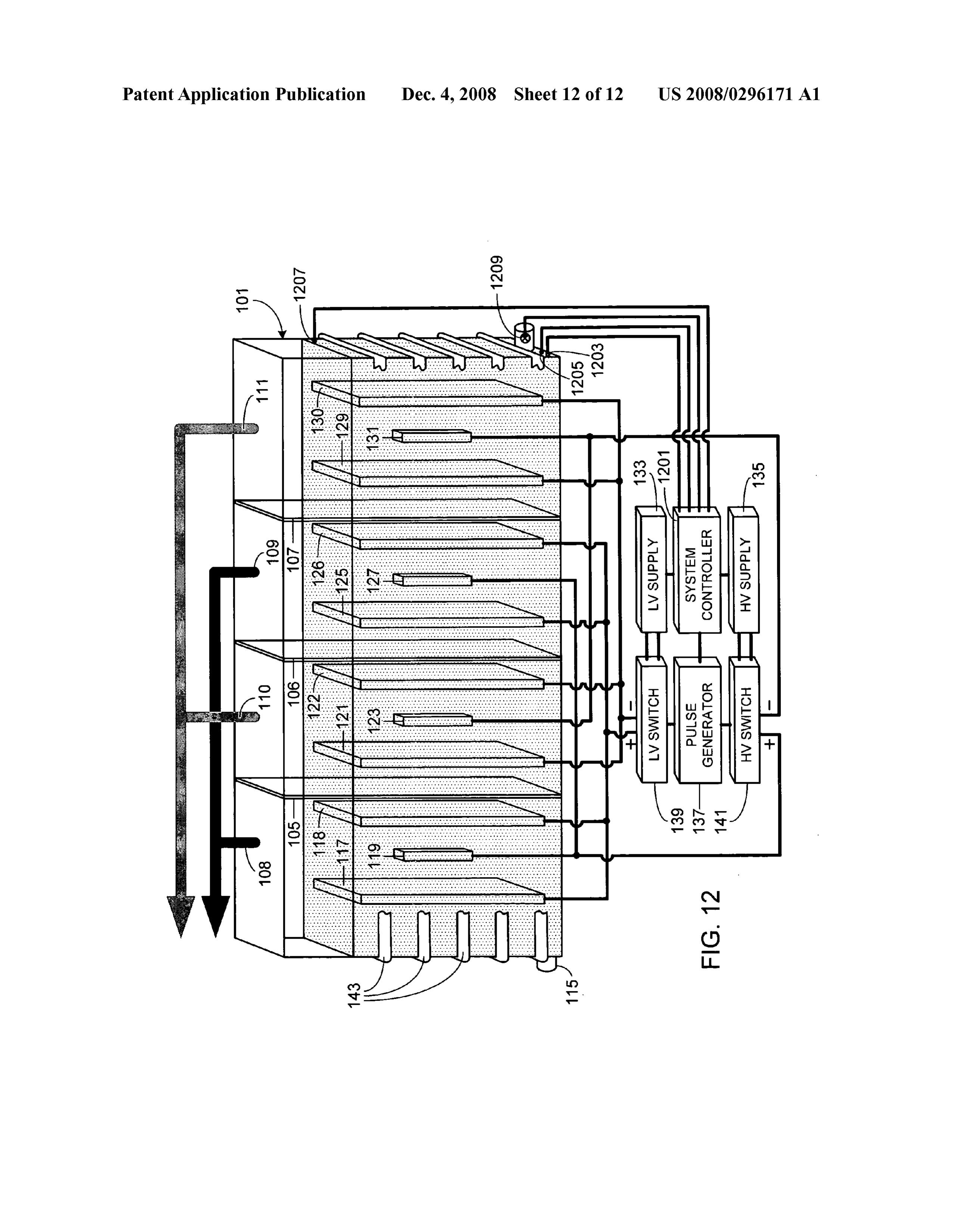
Drawing sheet — no readable text.
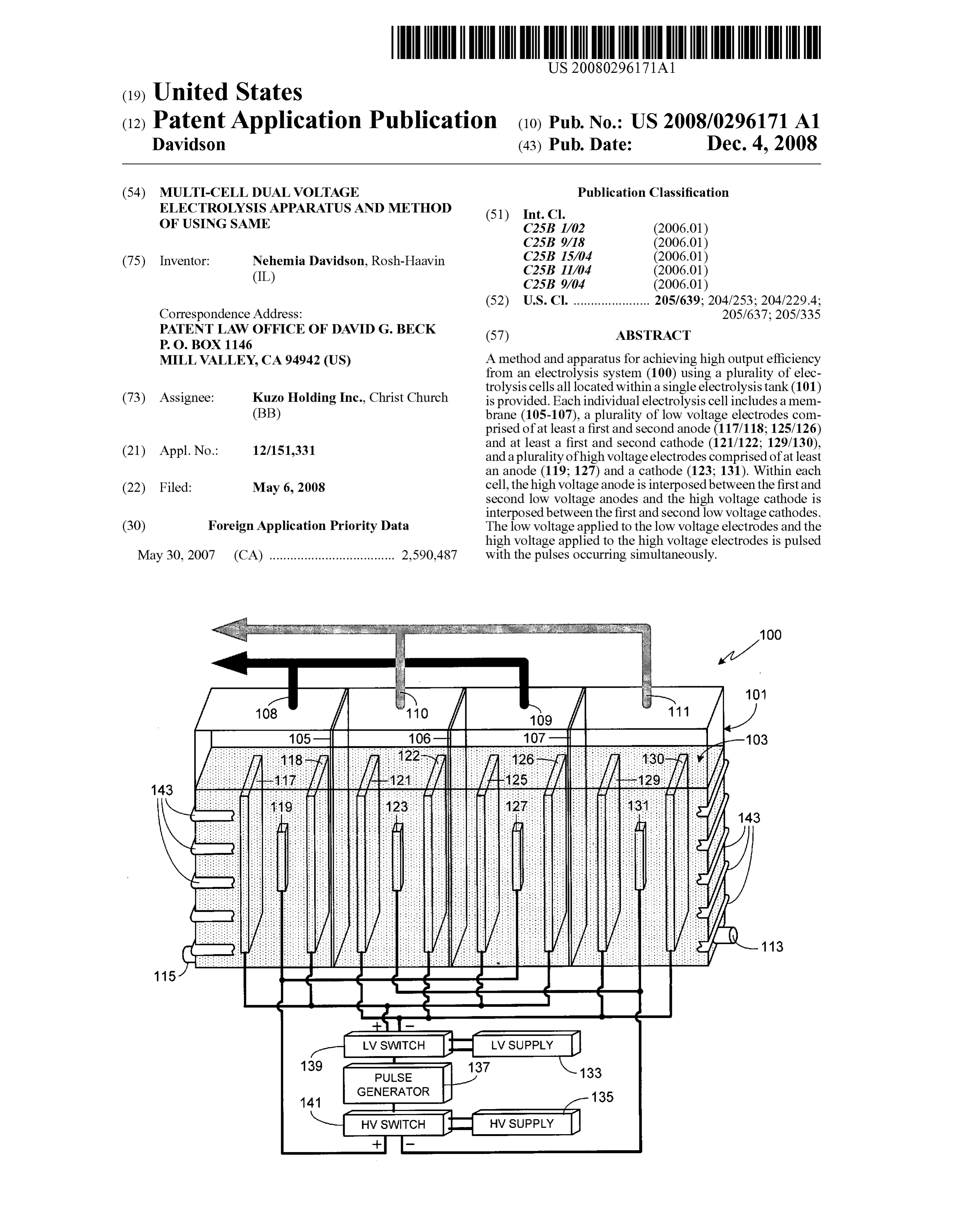
Page 7
Drawing sheet — no readable text.
Page 8
Drawing sheet — no readable text.
Page 9
Drawing sheet — no readable text.
Page 10
Patent Application Publication Dec. 4, 2008 Sheet 9 of 12 US 2008/0296.171 A1
FILL ELECTROLYSIS INITIAL PERIOD OF
903 W 917
SET INITIAL PULSE SYSTEM OUTPUT
OPTIMIZED
SET INITIAL HIGH PULSE FREOUENCY
OPTIMIZED
OPTIMIZATION
COMPLETE
SUSPENDED
Page 11
Patent Application Publication Dec. 4, 2008 Sheet 10 of 12 US 2008/0296.171 A1
FILL ELECTROLYSIS INITIAL PERIOD OF
903 O 917
SET INITIAL PULSE SYSTEM OUTPUT
OPTIMIZED
SET INITIAL HIGH PULSE FREOUENCY
VOLTAGE OUTPUT
OPTIMIZED
ELECTROLYSIS HIGHVOLTAGE
SYSTEM OUTPUT
MONITORED
FIG 10
Page 12
Drawing sheet — no readable text.
Page 13
Drawing sheet — no readable text.
Page 14
US 2008/0296.171 A1 Dec. 4, 2008
MULTI-CELL DUAL VOLTAGE this process has proven difficult to implement due to the ELECTROLYSIS APPARATUS AND METHOD tendency of the hydrogen and oxygen to recombine at the OF USING SAME technique's high operating temperatures.
0006. A high temperature heat source, for example a geo
CROSS-REFERENCE TO RELATED thermal source, can also be used as a replacement for fossil APPLICATION fuel. In Such systems the heat source raises the temperature of water Sufficiently to produce Steam, the steam driving a tur 0001 Under 35 U.S.C. 119, the present application claims bine generator which, in turn, produces electricity. Alter the benefit of the earlier filing date and the right of priority to nately the heat Source can raise the temperature of a liquid that Canadian Patent Application Serial No. 2,590,487, filed May has a lower boiling temperature than water, Such as isopen 30, 2007, the disclosure of which is hereby incorporated by tane, which can also be used to drive a turbine generator. reference for any and all purposes. Alternately the heat source can be used as a fossil fuel
FIELD OF THE INVENTION
replacement for non-electrical applications, such as heating buildings.
0002 The present invention relates generally to electroly 0007 Although a variety of alternatives to fossil fuels in sis systems and, more particularly, to a high efficiency elec addition to hydrogen and geothermal sources have been trolysis system and methods of using same. devised, to date none of them have proven acceptable for a variety of reasons ranging from cost to environmental impact
BACKGROUND OF THE INVENTION to availability. Accordingly, what is needed is a new energy Source, or a more efficient form of a current alternative energy 0003) Fossil fuels, in particular oil, coal and natural gas, source, that can effectively replace fossil fuels without requir represent the primary sources of energy in today's world. ing an overly complex distribution system. The present inven Unfortunately in a world of rapidly increasing energy needs, tion provides such a system and method of use. dependence on any energy source of finite size and limited regional availability has dire consequences for the world's SUMMARY OF THE INVENTION economy. In particular, as a country's need for energy increases, so does its Vulnerability to disruption in the Supply 0008. The present invention provides a method and appa of that energy. Additionally, as fossil fuels are the largest ratus for achieving high output efficiency from an electrolysis single source of carbon dioxide emissions, a greenhouse gas, system using a plurality of electrolysis cells all located within continued reliance on Such fuels can be expected to lead to a single electrolysis tank. Each individual electrolysis cell continued global warming. Accordingly it is imperative that includes a membrane which separates the portion of the elec alternative, clean and renewable energy sources be developed trolysis tank containing that electrolysis cell into two regions. that can replace fossil fuels. Additionally, each electrolysis cell includes a plurality of low 0004 Hydrogen-based fuel is currently one of the leading Voltage electrodes and a plurality of high Voltage electrodes. contenders to replace fossil fuel. There are a number of tech The plurality of low voltage electrodes includes at least a first niques that can be used to produce hydrogen, although the and second low Voltage anode contained within the first primary technique is by Steam reforming natural gas. In this region of the electrolysis cell and at least a first and second process thermal energy is used to react natural gas with steam, low Voltage cathode contained within the second region of the creating hydrogen and carbon dioxide. This process is well electrolysis cell. The plurality of high voltage electrodes developed, but due to its reliance on fossil fuels and the includes at least a first high Voltage anode contained within release of carbon dioxide during production, it does not alle the first region of the electrolysis cell and interposed between viate the need for fossil fuels nor does it lower the environ the first and second low Voltage anodes, and a first high mental impact of its use over that of traditional fossil fuels. Voltage cathode contained within the second region of the Other, less developed hydrogen producing techniques include electrolysis cell and interposed between the first and second (i) biomass fermentation in which methane fermentation of low voltage cathodes. The low voltage applied to the low high moisture content biomass creates fuel gas, a small por Voltage electrodes is pulsed as is the high Voltage applied to tion of which is hydrogen; (ii) biological water splitting in the high Voltage electrodes, the low Voltage pulses and the which certain photosynthetic microbes produce hydrogen high Voltage pulses being timed to occur simultaneously. from water during their metabolic activities; (iii) photoelec 0009 Preferably the low and high voltage pulses occurat trochemical processes using either soluble metal complexes a frequency between 50 Hz and 1 MHz, and more preferably as a catalyst or semiconducting electrodes in a photochemical at a frequency of between 100 Hz, and 10 kHz. The pulse cell; (iv) thermochemical water splitting using chemicals duration is preferably between 0.01 and 75 percent of the time Such as bromine or iodine, assisted by heat, to split water period defined by the frequency, and more preferably molecules, (v) thermolysis in which concentrated Solar between 1 and 50 percent of the time period defined by the energy is used to generate temperatures high enough to split frequency. Preferably the ratio of the high voltage to the low methane into hydrogen and carbon; and (vi) electrolysis. voltage is at least 5:1, more preferably within the range of 5:1 0005 Electrolysis as a means of producing hydrogen has to 100:1, still more preferably within the range of 5:1 to 33:1, been known and used for over 80 years. In general, electroly and still more preferably within the range of 5:1 to 20:1. sis of water uses two electrodes separated by an ion conduct Preferably the low voltage is between 3 and 1500 volts, more ing electrolyte. During the process hydrogen is produced at preferably between 12 and 750 volts. Preferably the high the cathode and oxygen is produced at the anode, the two voltage is between 50 volts and 50 kilovolts, more preferably reaction areas separated by an ion conducting diaphragm. between 100 volts and 5 kilovolts. Electricity is required to drive the process. An alternative to 0010 Preferably the liquid within the tank is comprised of conventional electrolysis is high temperature electrolysis, one or more of water, deuterated water, tritiated water, semi also known as steam electrolysis. This process uses heat, for heavy water, heavy oxygen water, and/or any other water example produced by a Solar concentrator, as a portion of the containing an isotope of either hydrogen or oxygen. Prefer energy required to cause the needed reaction. Although low ably the liquid within the electrolysis tank includes an elec ering the electrical consumption of the process is desirable, trolyte with a concentration in the range of 0.05 to 10 percent
Page 15
US 2008/0296.171 A1 Dec. 4, 2008
by weight, more preferably in the range of 0.05 to 2.0 percent example, as a heat generator. Electrolysis system 100 by weight, and still more preferably in the range of 0.1 to 0.5 includes a tank 101 comprised of a non-conductive material, percent by weight. the size of the tank depending primarily upon the desired 0011. The electrodes can be fabricated from a variety of output level for the system, for example the desired heat materials, although preferably the material for each electrode production. Although tank 101 is shown as having a rectan is selected from the group consisting of steel, nickel, copper, gular shape, it will be appreciated that the invention is not so iron, stainless steel, cobalt, manganese, Zinc, titanium, plati limited and that tank 101 can utilize other shapes, for example num, palladium, aluminum, lithium, magnesium, boron, car cylindrical, square, irregularly-shaped, etc. Tank 101 is Sub bon, graphite, carbon-graphite, metal hydrides and alloys stantially filled with liquid 103. In at least one preferred thereof. embodiment, liquid 103 is comprised of water with an elec 0012. In at least one embodiment, the electrolysis system trolyte, the electrolyte being either an acid electrolyte or a is cooled. Cooling is preferably achieved by thermally cou base electrolyte. Exemplary electrolytes include potassium pling at least a portion of the electrolysis system to a portion hydroxide and sodium hydroxide. The term “water as used of a conduit containing a heat transfer medium. The conduit herein refers to water (HO), deuterated water (deuterium can Surround the electrolysis tank, be integrated within the oxide or DO), tritiated water (tritium oxide or TO), semi walls of the electrolysis tank, or be contained within the heavy water (HDO), heavy oxygen water (HO or HO) electrolysis tank. or any other water containing an isotope of either hydrogen or 0013. In at least one embodiment, the electrolysis system oxygen, either singly or in any combination thereof (for also contains a system controller. The system controller can example, a combination of H2O and D2O). be used to perform system optimization, either during an 0028. A typical electrolysis system used to decompose initial optimization period or repeatedly throughout system water into hydrogen and oxygen gases utilizes relatively high operation. concentrations of electrolyte. The present invention, how 0014. A further understanding of the nature and advan ever, has been found to work best with relatively low electro tages of the present invention may be realized by reference to lyte concentrations, thereby maintaining a relatively high the remaining portions of the specification and the drawings. initial water resistivity. Preferably the water resistivity prior
BRIEF DESCRIPTION OF THE DRAWINGS
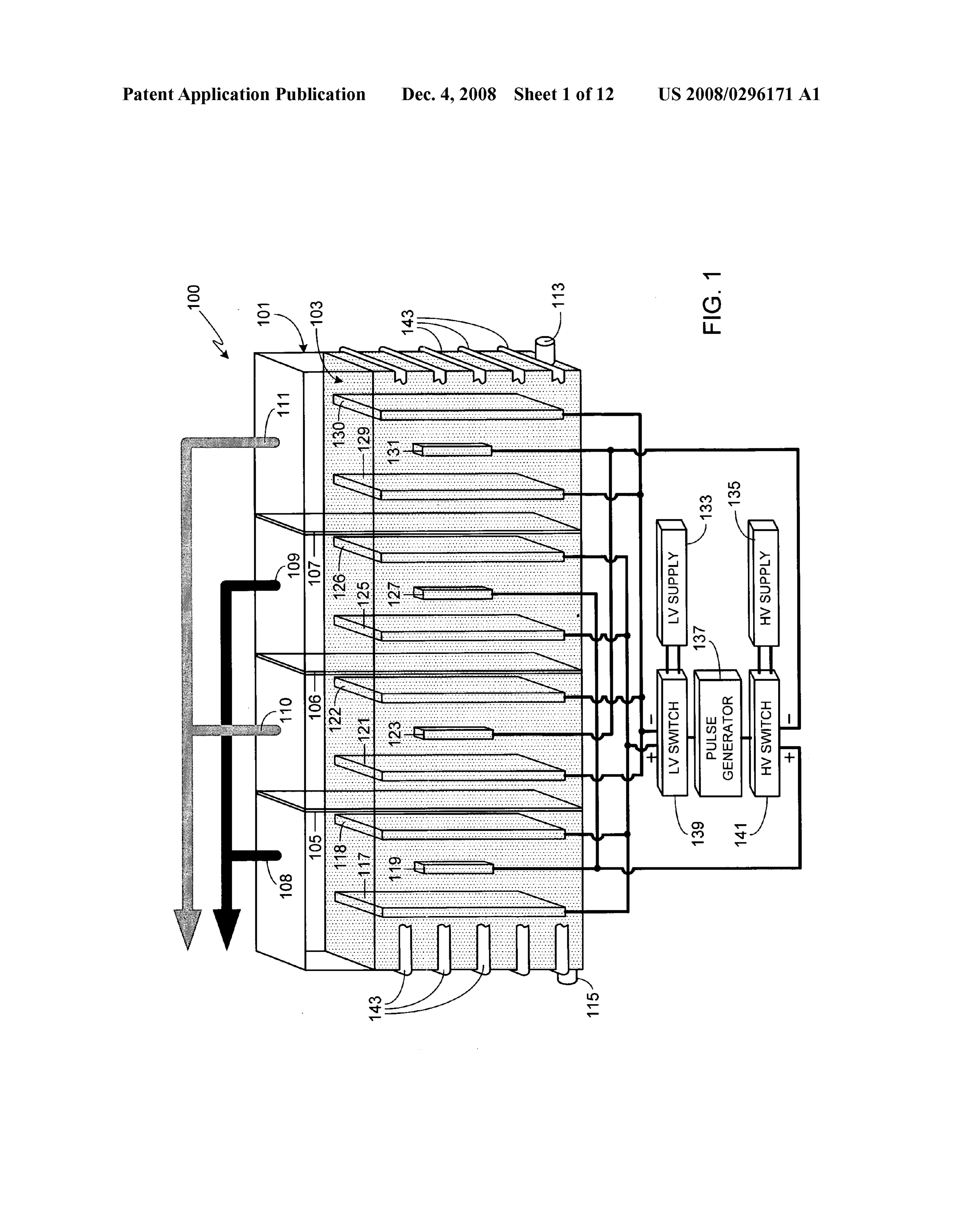
to the addition of an electrolyte is on the order of 1 to 28 megohms. Preferably the concentration of electrolyte is in the 0015 FIG. 1 is an illustration of an exemplary embodi range of 0.05 percent to 10 percent by weight, more prefer ment of the invention utilizing a three cell configuration; ably the concentration of electrolyte is in the range of 0.05 0016 FIG. 2 is an illustration of an alternate embodiment percent to 2.0 percent by weight, and still more preferably the based on the configuration shown in FIG. 1 utilizing multiple concentration of electrolyte is in the range of 0.1 percent to sets of low voltage electrodes for each cell; 0.5 percent by weight.
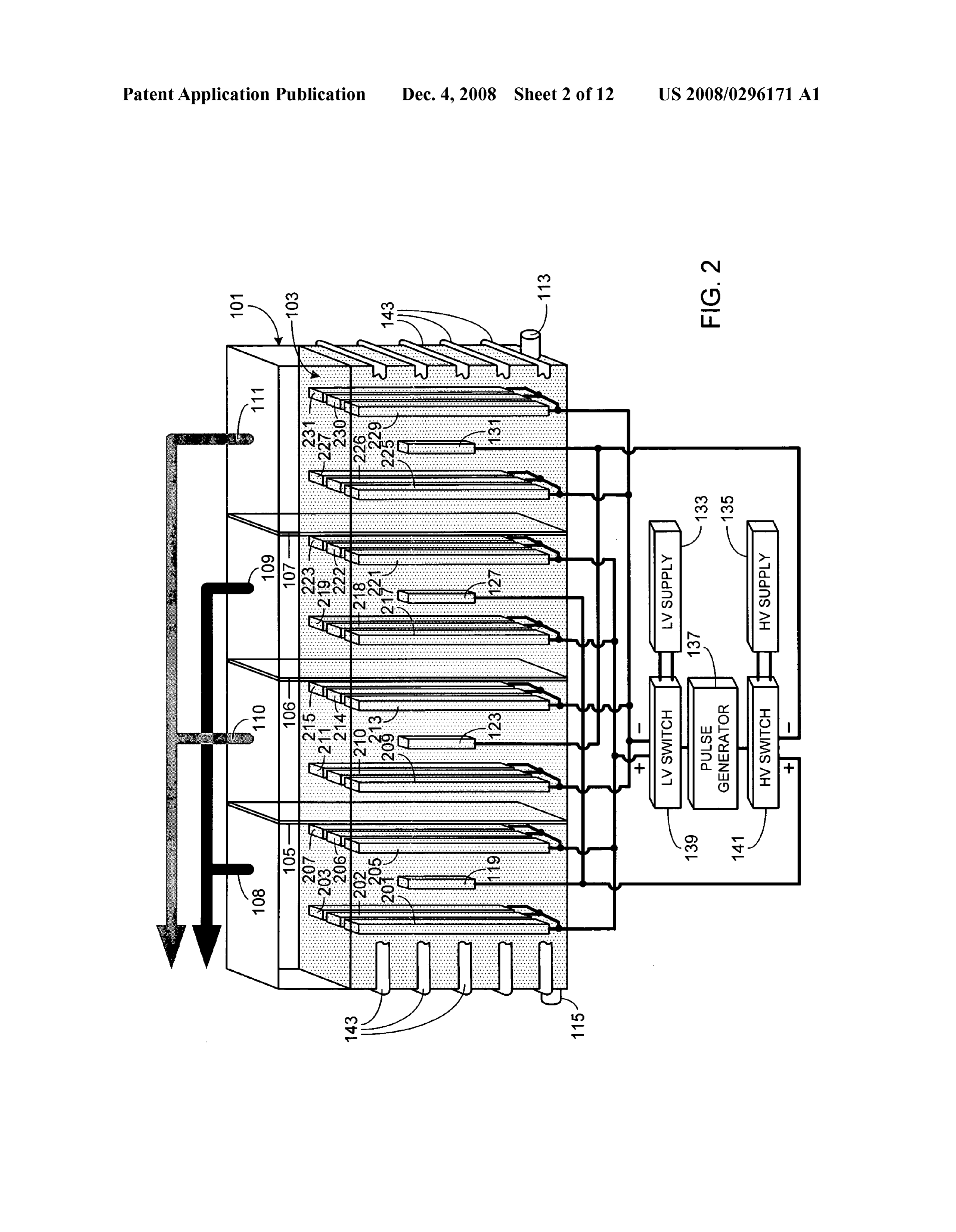
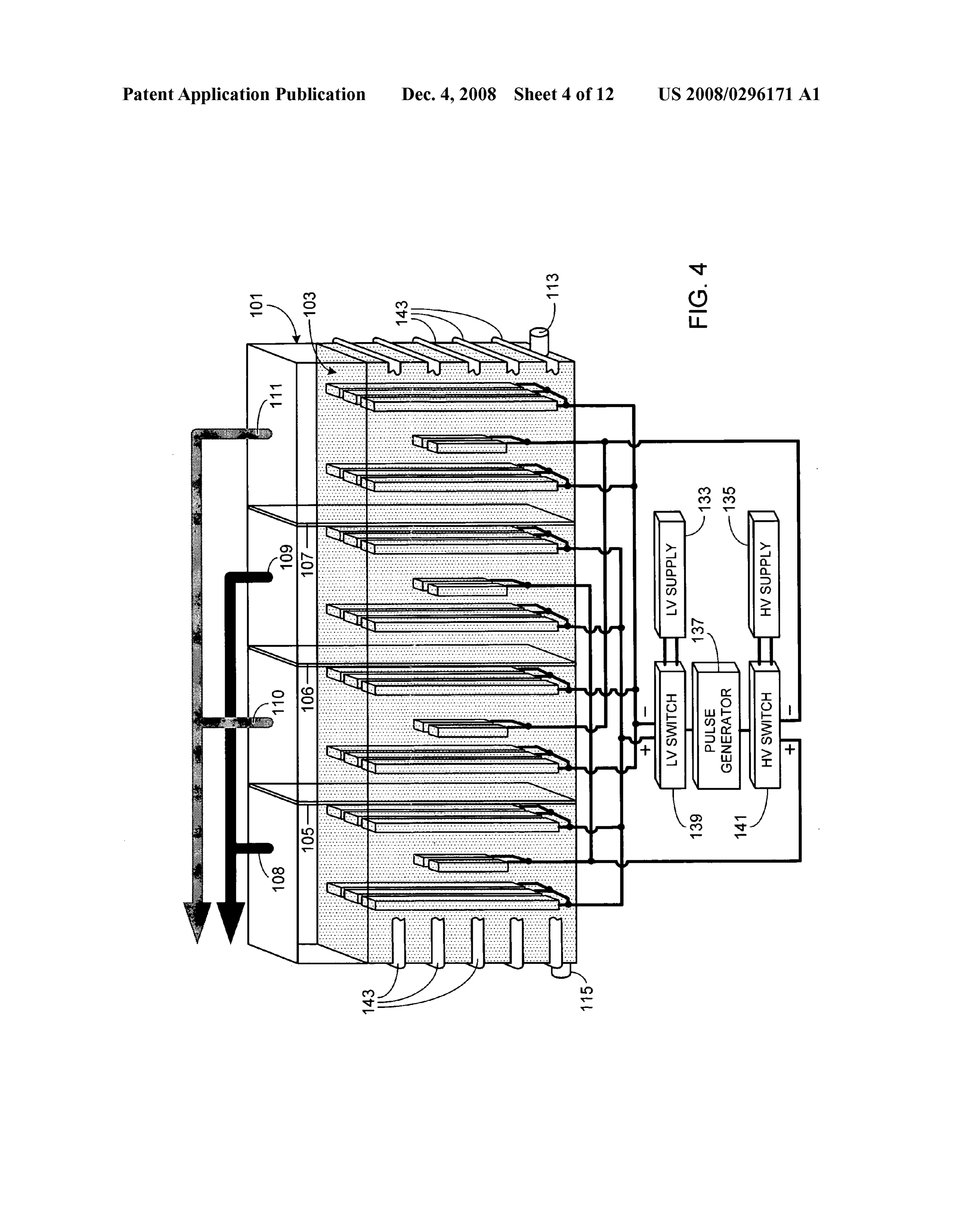
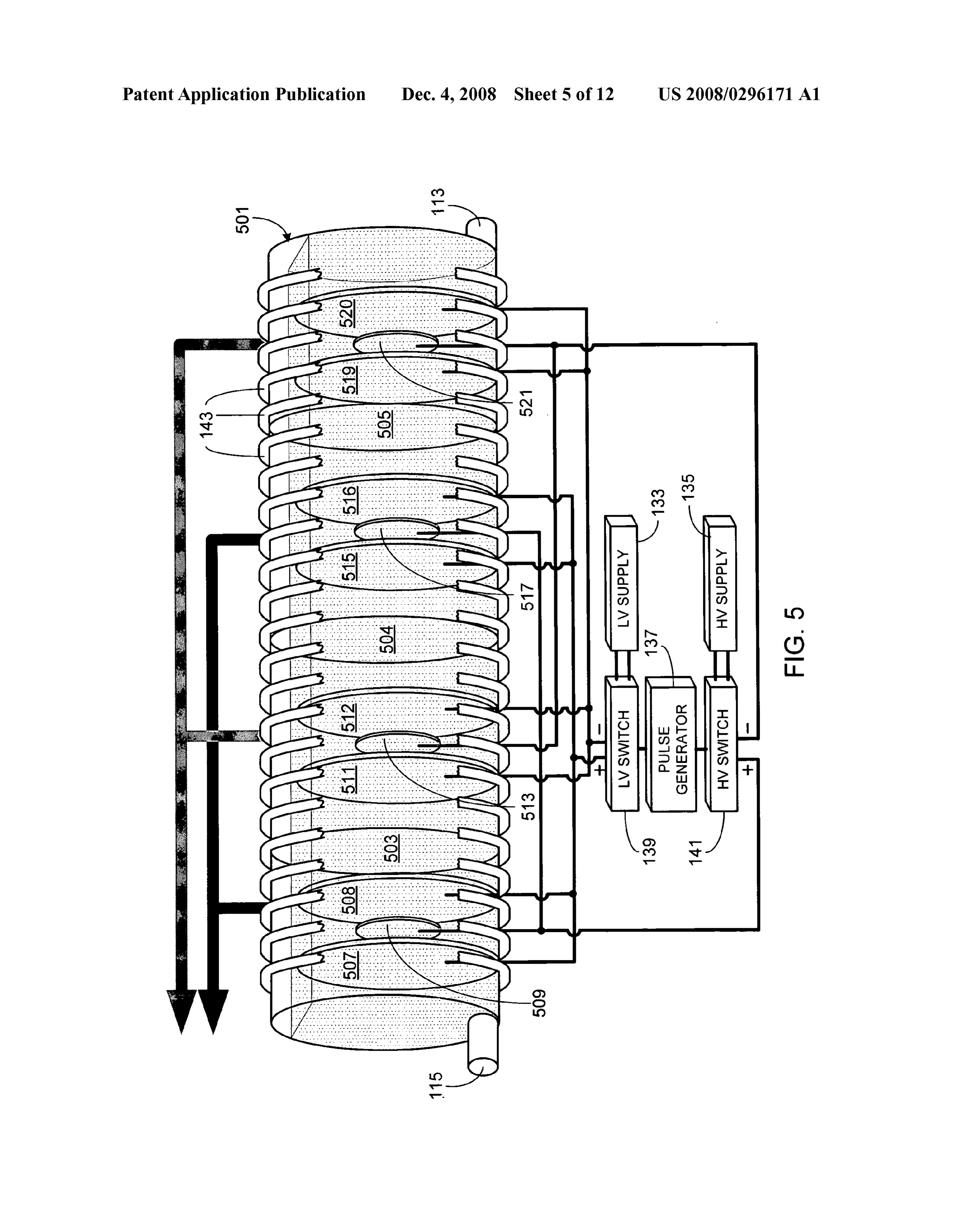
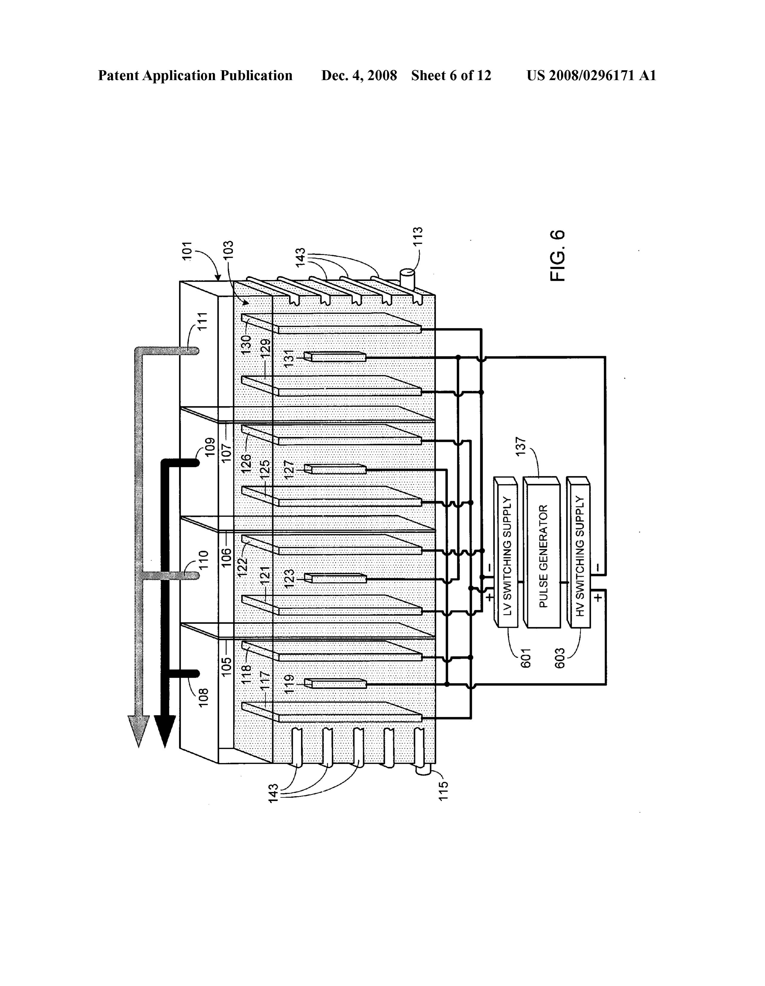
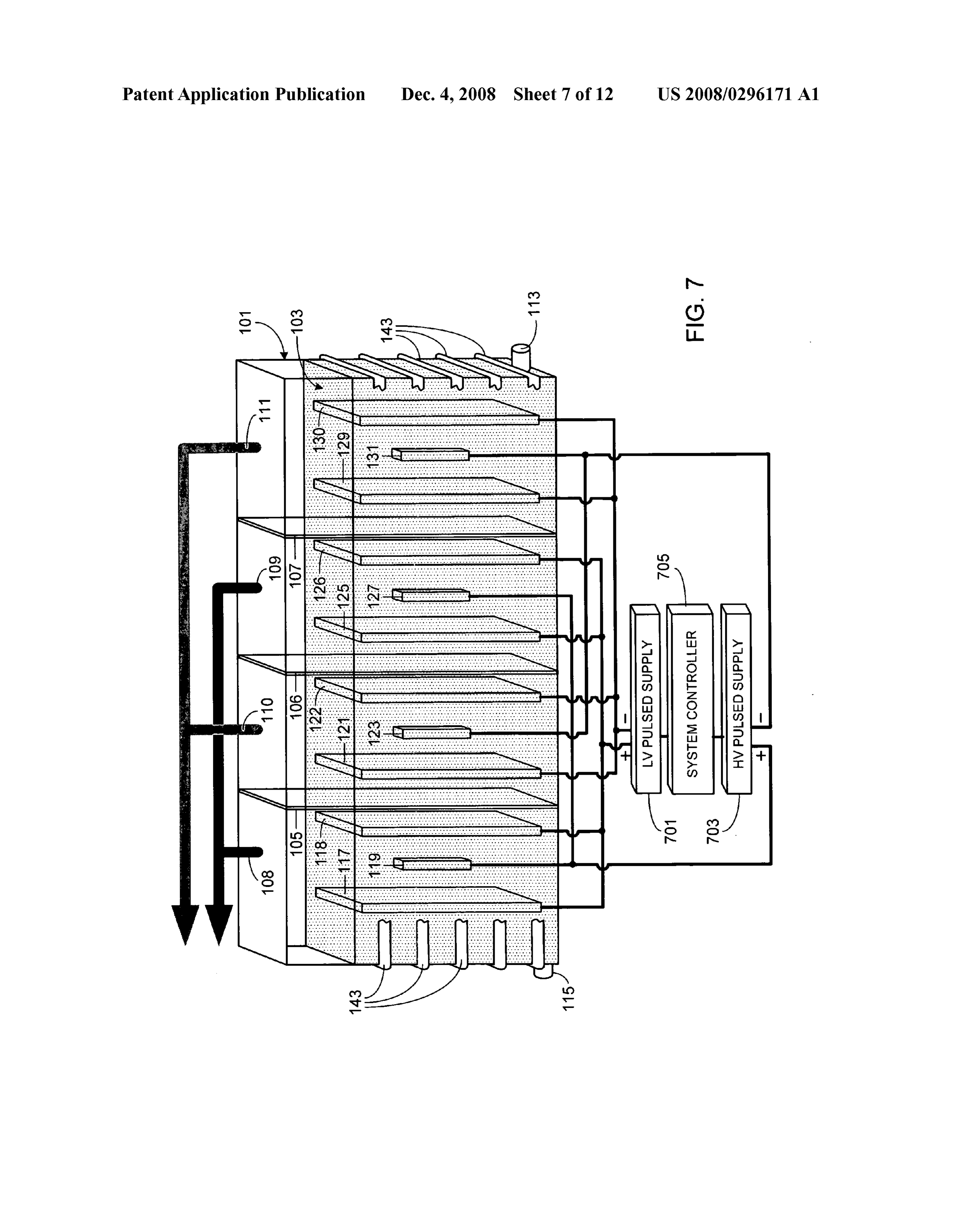
0017 FIG. 3 is an illustration of an alternate embodiment 0029. The electrolysis system of the invention uses two based on the configuration shown in FIG. 1 utilizing multiple types of electrodes, one comprised of low Voltage electrodes sets of high Voltage electrodes for each cell; and the other comprised of high Voltage electrodes. The sys 0.018 FIG. 4 is an illustration of an alternate embodiment tem of the invention also includes multiple electrolysis cells, based on the configuration shown in FIG. 1 utilizing multiple an electrolysis cell defined herein as having at least two low sets of low voltage electrodes and multiple sets of high volt Voltage cathodes, at least two low Voltage anodes, at least one age electrodes for each cell; high Voltage cathode interposed between the two low Voltage 0.019 FIG. 5 is an illustration of an alternate embodiment cathodes and at least one high Voltage anode interposed utilizing a cylindrically-shaped tank; between the two low voltage anodes. Furthermore the cathode 0020 FIG. 6 is an illustration of an alternate embodiment electrodes (low and high Voltage) and the anode electrodes based on the configuration shown in FIG. 1 utilizing switch (low and high Voltage) within each cell are separated by a ing power Supplies; membrane, specifically membranes 105-107 in the illustrated 0021 FIG. 7 is an illustration of an alternate embodiment embodiment. Accordingly the embodiment illustrated in FIG. based on the configuration shown in FIG. 1 utilizing switch 1 includes three electrolysis cells. It should be understood that ing power Supplies with internal pulse generators and a sys the invention is not limited to an electrolysis system with a tem controller; specific number of cells, rather the number of cells depends 0022 FIG. 8 is an illustration of one mode of operation; primarily on the desired output level (e.g., heat production) 0023 FIG. 9 is an illustration of an alternate mode of and the size of the electrolysis tank. operation that includes initial process optimization steps; 0030 Membranes 105-107 permition/electron exchange 0024 FIG. 10 is an illustration of an alternate, and pre between the two regions of each cell while keeping separate ferred, mode of operation in which the process undergoes the oxygen and hydrogen bubbles produced during electroly continuous optimization; sis. Maintaining separate hydrogen and oxygen gas regions is 0.025 FIG.11 is an illustration of an alternate embodiment important as a means of minimizing the risk of explosions due of FIG. 1 utilizing multiple low voltage supplies and multiple to the inadvertent recombination of the two gases. Addition high Voltage Supplies; and ally, separating the regions allows the collection of pure 0026 FIG.12 is an illustration of an alternate embodiment hydrogen gas and pure oxygen gas. Accordingly similar of FIG. 1 that includes a system controller. polarity electrodes are grouped together with the membranes
DESCRIPTION OF THE SPECIFIC
keeping groups separate. Thus in the exemplary embodiment
EMBODIMENTS shown in FIG. 1, only anodes are positioned between mem brane 105 and the left side of electrolysis tank 101; only 0027 FIG. 1 is an illustration of an exemplary, and pre cathodes are positioned between membranes 105 and 106: ferred, embodiment of the invention which can be used, for only anodes are positioned between membranes 106 and 107;
Page 16
US 2008/0296.171 A1 Dec. 4, 2008
and only cathodes are positioned between membrane 107 and 0035. Preferably and as shown, the faces of the individual the right side of electrolysis tank 101. Exemplary membrane electrodes are parallel to one another. It should be understood, materials include, but are not limited to, polypropylene, tet however, that the faces of the electrodes do not have to be rafluoroethylene, asbestos, etc. parallel to one another.
0031. As noted herein, the present system is capable of 0036. In a preferred embodiment, all of the electrodes are generating considerable heat. Accordingly, system compo comprised of titanium. In another preferred embodiment, all nents such as the electrolysis tank (e.g., tank 101) and the of the electrodes are comprised of stainless steel. It should be membranes (e.g., membranes 105-107) that are expected to appreciated, however, that other materials can be used and that the same material does not have to be used for both the be subjected to the heat generated by the system must be low Voltage and the high Voltage electrodes, nor does the fabricated from suitable materials and designed to indefi same material have to be used for both the low voltage anodes nitely accommodate the intended operating temperatures as and the low Voltage cathodes, nor does the same material have well as the internal tank pressure. For example, in at least one to be used for both the high voltage anodes and the high preferred embodiment the system is designed to operate at a Voltage cathodes. In addition to titanium and stainless steel, temperature of approximately 90° C. at standard pressure. In other exemplary materials that can be used for the low voltage an alternate exemplary embodiment, the system is designed electrodes and the high Voltage electrodes include, but are not to operate at elevated temperatures (e.g., 100° C. to 150°C.) limited to, copper, iron, stainless steel, cobalt, manganese, and at sufficient pressure to prevent boiling of liquid 103. In Zinc, nickel, platinum, palladium, aluminum, lithium, mag yet another alternate exemplary embodiment, the system is nesium, boron, carbon, graphite, carbon-graphite, metal designed to operate at even higher temperatures (e.g., 200°C. hydrides and alloys of these materials. As used in the present to 350° C.) and higher pressures (e.g., sufficient to prevent specification, a metal hydride refers to any compound of a boiling). Accordingly, it will be understood that the choice of metal and hydrogen or an isotope of hydrogen (e.g., deute materials (e.g., for tank 101 and membranes 105-107) and the rium, tritium).
design of the system (e.g., tank wall thicknesses, fittings, etc.) 0037 Preferably the surface area of each of the faces of the will vary, depending upon the intended system operational low voltage electrodes (i.e., electrodes 117, 118, 121, 122, parameters, primarily temperature and pressure. 125, 126, 129 and 130 in FIG. 1) is a large percentage of the 0032. Other standard features of the electrolysis tank are cross-sectional area of tank 101, typically on the order of at gas outlets for any hydrogen and oxygen gases generated least 40 percent of the cross-sectional area of tank 101, and within the tank. In the exemplary embodiment shown in FIG. often between approximately 70 percent and 90 percent of the 1, the oxygen gas produced at the anodes will exit tank 101 at cross-sectional area of tank 101. The high voltage electrodes gas outlets 108-109 while hydrogen gas produced at the cath may be larger, Smaller or the same size as the low Voltage odes will exit the tank at gas outlets 110-111. Replenishment electrodes. Although the separation distance between elec trodes is dependent upon a variety of factors (e.g., tank size, of liquid 103 is preferably through a separate conduit, for Voltage/current, etc.), in at least one preferred embodiment example conduit 113. In at least one embodiment of the the separation between the closest low voltage electrodes invention, another conduit 115 is used to remove liquid 103 positioned on either side of a membrane (e.g., in FIG. 1 from the system. Alternately, each cell can include one or electrodes 118/121, electrodes 122/125 and electrodes 126/ more conduits for liquid 103 replenishment. If desired, a 129) is between 0.2 millimeters and 15 centimeters. single conduit can be used for both liquid removal and replen 0038 Preferably the ratio of the high voltage to the low ishment. It will be appreciated that the system can either be Voltage applied to the high Voltage and low Voltage elec periodically refilled or liquid 103 can be continuously added trodes, respectively, is at least 5:1, more preferably the ratio is at a very slow rate during system operation. between 5:1 and 100:1, still more preferably the ratio is 0033. In the embodiment illustrated in FIG. 1, each cell between 5:1 and 33:1, and even still more preferably the ratio includes four low Voltage electrodes (i.e., two cathodes and is between 5:1 and 20:1. Preferably the high voltage gener two anodes) and two high Voltage electrodes (i.e., one cathode ated by source 135 is within the range of 50 volts to 50 and one anode). In the illustrated embodiment, the first cell kilovolts, and more preferably within the range of 100 volts to includes low voltage anodes 117/118 and interposed high 5 kilovolts. Preferably the low voltage generated by source voltage anode 119, and includes low voltage cathodes 121/ 133 is within the range of 3 volts to 1500 volts, and more 122 and high voltage cathode 123. Noting that adjacent cells preferably within the range of 12 volts to 750 volts. preferably co-use sets of electrodes as shown, the second cell 0039. Rather than continually apply voltage to the elec includes low voltage cathodes 121/122 and high voltage cath trodes, sources 133 and 135 are pulsed, preferably at a fre ode 123, and includes low voltage anodes 125/126 and inter quency between 50 Hz and 1 MHz, and more preferably at a posed high voltage anode 127. The third cell includes low frequency of between 100 Hz, and 10 kHz. The pulse width voltage anodes 125/126 and interposed high voltage anode (i.e., pulse duration) is preferably between 0.01 and 75 per 127, and includes low voltage cathodes 129/130 and high cent of the time period defined by the frequency, and more voltage cathode 131. preferably between 1 and 50 percent of the time period 0034. In FIG. 1, low voltage power source 133 supplies defined by the frequency. Thus, for example, for a frequency power to all of the low Voltage electrodes and high Voltage of 150 Hz, the pulse duration is preferably in the range of 0.67 power source 135 supplies power to all of the high voltage microseconds to 5 milliseconds, and more preferably in the electrodes. As described and illustrated, voltage source 133 is range of 66.7 microseconds to 3.3 milliseconds. Alternately, referred to and labeled as a low voltage source not because for example, for a frequency of 1 kHz, the pulse duration is of the absolute voltage produced by the source, but because preferably in the range of 0.1 microseconds to 0.75 millisec the output of voltage source 133 is maintained at a lower onds, and more preferably in the range of 10 microseconds to output voltage than the output of voltage source 135. 0.5 milliseconds. Additionally, the voltage pulses are applied
Page 17
US 2008/0296.171 A1 Dec. 4, 2008
simultaneously to the high Voltage and low Voltage electrodes 121 with three low voltage electrodes 209-211, replacing low via sources 135 and 133, respectively. In other words, in the voltage electrode 122 with three low voltage electrodes 213 embodiment illustrated in FIG. 1, the voltage pulses applied 215, replacing low voltage electrode 125 with three low volt to high voltage electrodes 119/123/127/131 coincide with the age electrodes 217-219, replacing low voltage electrode 126 pulses applied to low voltage electrodes 117/118/121/122/ with three low voltage electrodes 221-223, replacing low 125/126/129/130. Although voltage sources 133 and 135 can voltage electrode 129 with three low voltage electrodes 225 include internal means for pulsing the respective outputs from 227, and replacing low voltage electrode 130 with three low each source, preferably an external pulse generator 137 con voltage electrodes 229-231.
trols a pair of switches, i.e., a low voltage switch 139 and a high voltage switch 141 which, in turn, control the output of 0043 FIG. 3 illustrates an alternate embodiment of the voltage sources 133 and 135 as shown, and as described system shown in FIG. 1, the alternate configuration replacing above. Other means for pulsing the Voltage sources are clearly high voltage electrode 119 with two high voltage electrodes envisioned, for example using Switching power Supplies 301-302, replacing high voltage electrode 123 with two high coupled to an external pulse generator or using Switching voltage electrodes 303-304, replacing high voltage electrode power Supplies with internal pulse generators. If multiple 127 with two high voltage electrodes 305-306, and replacing pulse generators are used, for example one pulse generator high voltage electrode 131 with two high voltage electrodes coupled to the low Voltage source and a second pulse genera 307-3O8.
tor coupled to the high Voltage source, preferably means Such 0044 FIG. 4 illustrates an alternate embodiment of the as a system controller are used to insure that the pulses gen system shown in FIG. 1, the alternate embodiment utilizing erated by the individual pulse generators are simultaneous. the low voltage configuration shown in FIG. 2 and the high 0040. As previously noted, the electrolysis process of the voltage configuration shown in FIG. 3. invention generates considerable heat. To withdraw that heat 004.5 FIG. 5 illustrates an alternate embodiment of the so that it can be used, and to prevent the liquid within the tank system shown in FIG. 1, the alternate configuration replacing from becoming too hot and boiling at a given temperature, tank 101 with a horizontally configured cylindrical tank 501, and to prevent possible damage to those system components replacing membrane 105 with an appropriately shaped mem that may be susceptible to damage, in the preferred embodi brane 503, replacing membrane 106 with an appropriately ments of the invention the system includes means to actively shaped membrane 504, replacing membrane 107 with an cool the system to within an acceptable temperature range. appropriately shaped membrane 505, replacing low voltage For example, in at least one preferred embodiment the cool electrode 117 with disc-shaped low voltage electrode 507, ing system does not allow the temperature to exceed 90° C. replacing low voltage electrode 118 with disc-shaped low Although it will be appreciated that the invention is not lim voltage electrode 508, replacing high voltage electrode 119 ited to a specific type of cooling system or a specific imple with disc-shaped high voltage electrode 509, replacing low mentation of the cooling system, in at least one embodiment voltage electrode 121 with disc-shaped low voltage electrode the electrolysis tank is surrounded by a coolant conduit 143, 511, replacing low voltage electrode 122 with disc-shaped portions of which are shown in FIGS. 1-7, 11 and 12. Within low Voltage electrode 512, replacing high Voltage electrode coolant conduit 143 is a heat transfer medium, for example 123 with disc-shaped high voltage electrode 513, replacing water. Coolant conduit 143 can either surround a portion of low voltage electrode 125 with disc-shaped low voltage elec the electrolysis tank as shown, or be contained within the trode 515, replacing low voltage electrode 126 with disc electrolysis tank, or be integrated within the walls of the shaped low Voltage electrode 516, replacing high Voltage electrolysis tank. The coolant pump and heat withdrawal electrode 127 with disc-shaped high voltage electrode 517, system is not shown in the figures as cooling systems are well replacing low voltage electrode 129 with disc-shaped low known by those of skill in the art. voltage electrode 519, replacing low voltage electrode 130 0041 As will be appreciated by those of skill in the art, with disc-shaped low voltage electrode 520, and replacing there are numerous minor variations of the system described high voltage electrode 131 with disc-shaped high voltage herein and shown in FIG. 1 that will function in substantially electrode 521.
the same manner as the disclosed system. As previously 0046. It will be appreciated that the supply electronics noted, alternate configurations can utilize fewer or greater (i.e., low/high Voltage Supplies, low/high Voltage Switches, numbers of cells, differently sized/shaped tanks, different pulse generator) shown in FIGS. 1-5 represent only one electrolytic solutions, and a variety of different electrode exemplary configuration and that other configurations can be configurations and materials. Additionally the system can used to Supply the requisite pulsed and timed power to the low utilize a range of input powers, frequencies and pulse widths voltage and high voltage electrodes within the cells of the (i.e., pulse duration). In general, the exact configuration electrolysis system of the invention. FIGS. 6 and 7 illustrate depends upon the desired output level as well as available two additional alternate, and exemplary, configurations. Spe space and power. FIGS. 2-5 illustrate a few alternate configu cifically, FIG. 6 illustrates a system similar to that shown in rations, including the use of multiple sets of low Voltage FIG. 1, except that low voltage supply 133 and low voltage electrodes for each cell (e.g., FIG. 2), multiple sets of high switch 139 are combined into a single low voltage switching voltage electrodes for each cell (e.g., FIG. 3), multiple sets of power supply 601. Similarly high voltage supply 135 and low Voltage and high Voltage electrodes for each cell (e.g., high Voltage Switch 141 are combined into a single high FIG. 4), and a horizontal cylindrical tank (e.g., FIG. 5). voltage switching power supply 603. The embodiment illus 0.042 FIG. 2 illustrates an alternate embodiment of the trated in FIG. 7 combines the pulse generation within the system shown in FIG. 1, the alternate configuration replacing power Supplies, i.e., low Voltage Supply 701 and high Voltage low voltage electrode 117 with three low voltage electrodes supply 703, and then uses a system controller 705 to coordi 201-203, replacing low voltage electrode 118 with three low nate the low Voltage pulses and the high Voltage pulses pro voltage electrodes 205-207, replacing low voltage electrode duced by the two systems.
Page 18
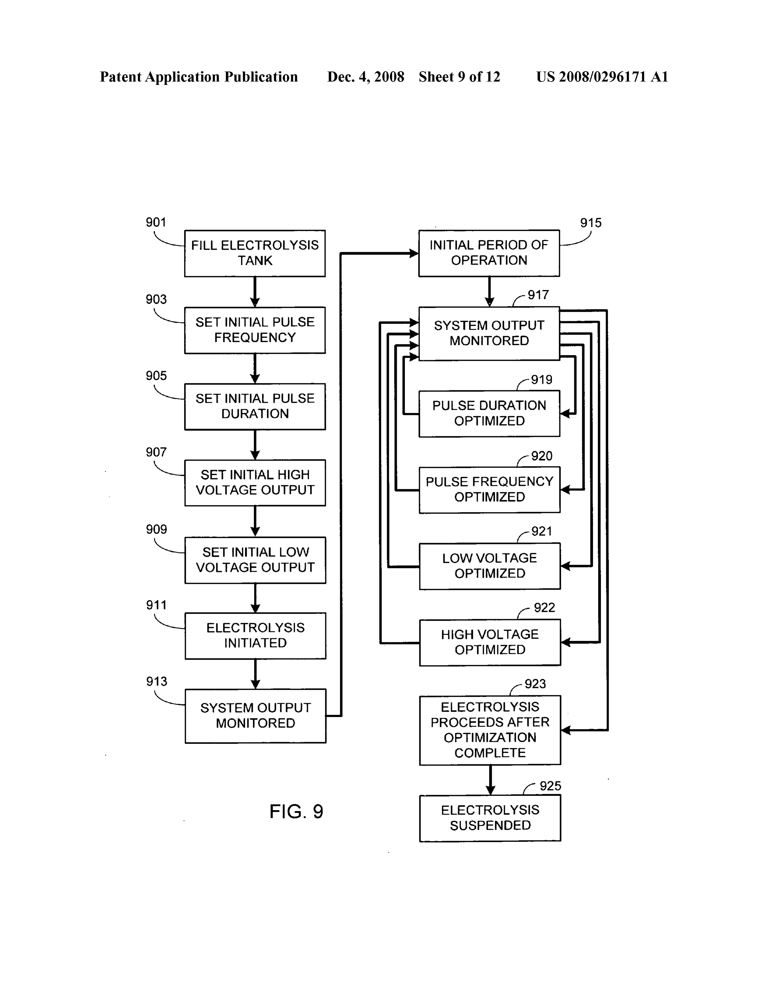
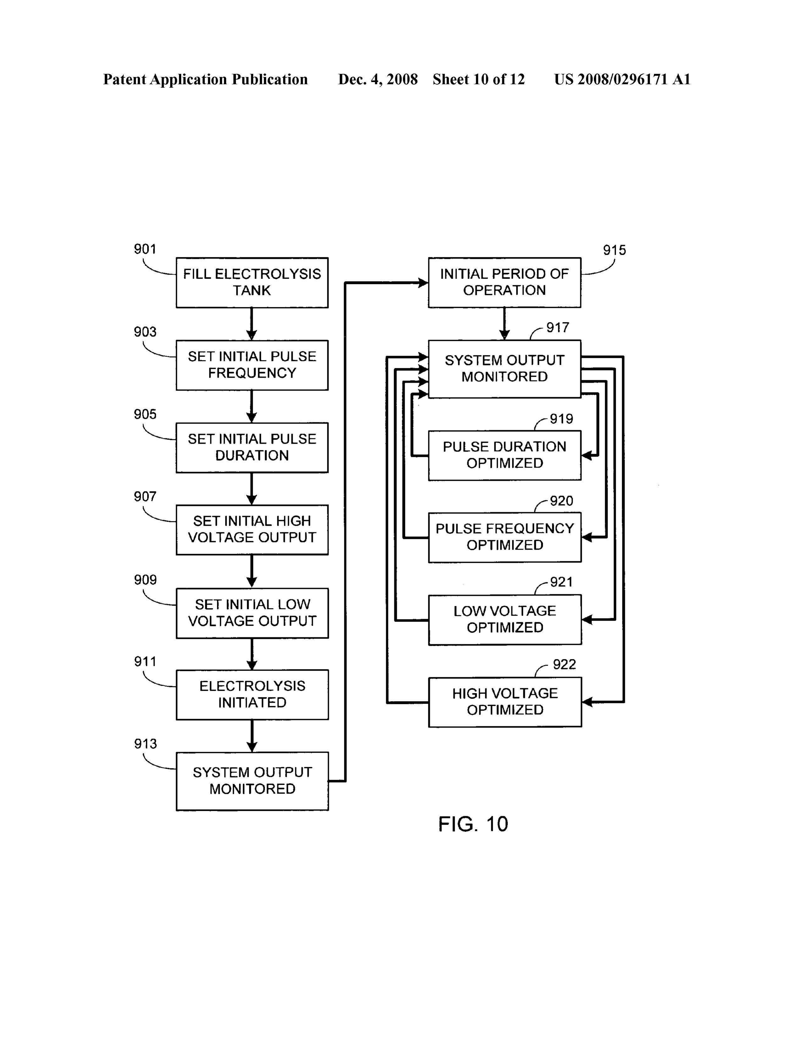
US 2008/0296.171 A1 Dec. 4, 2008
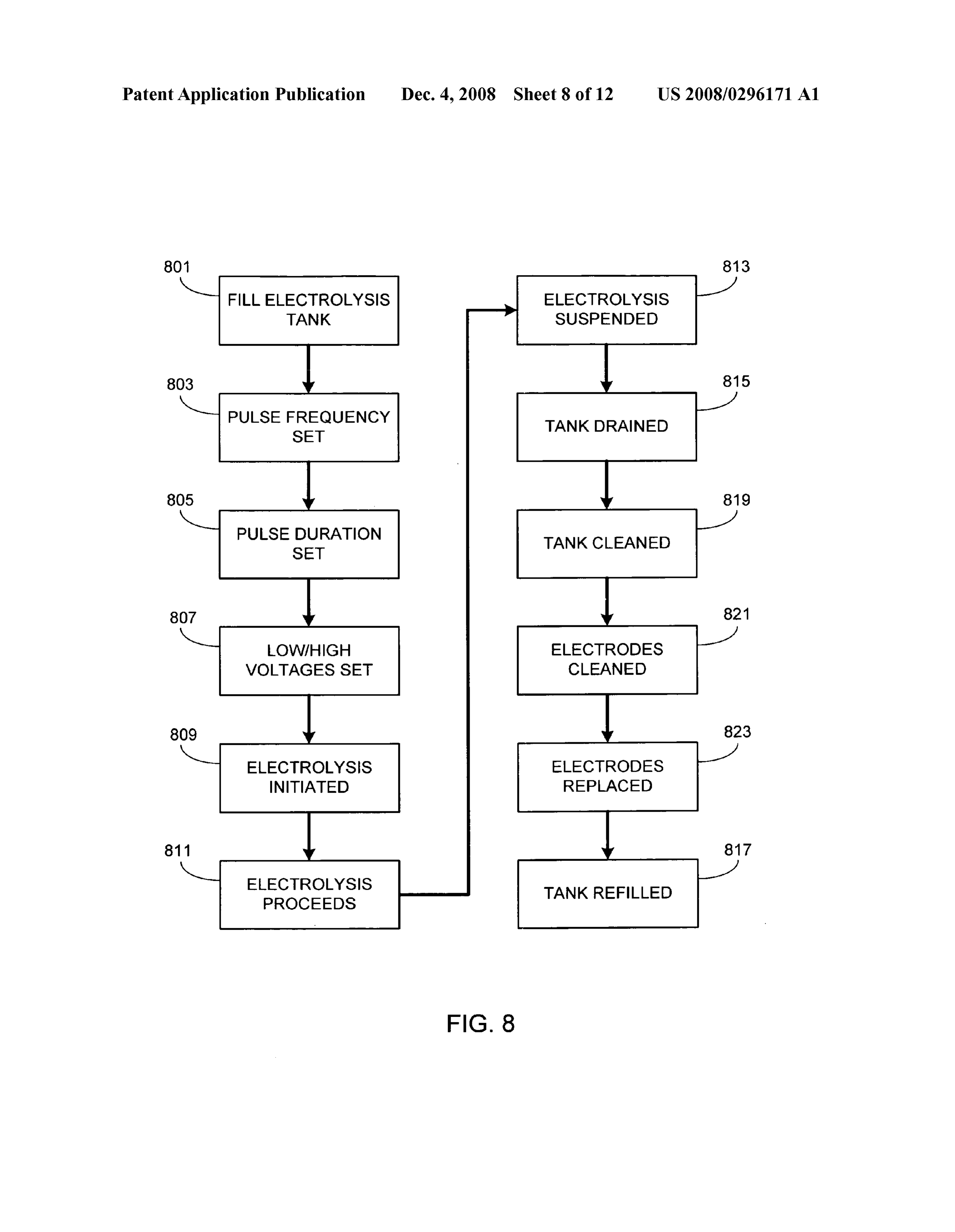
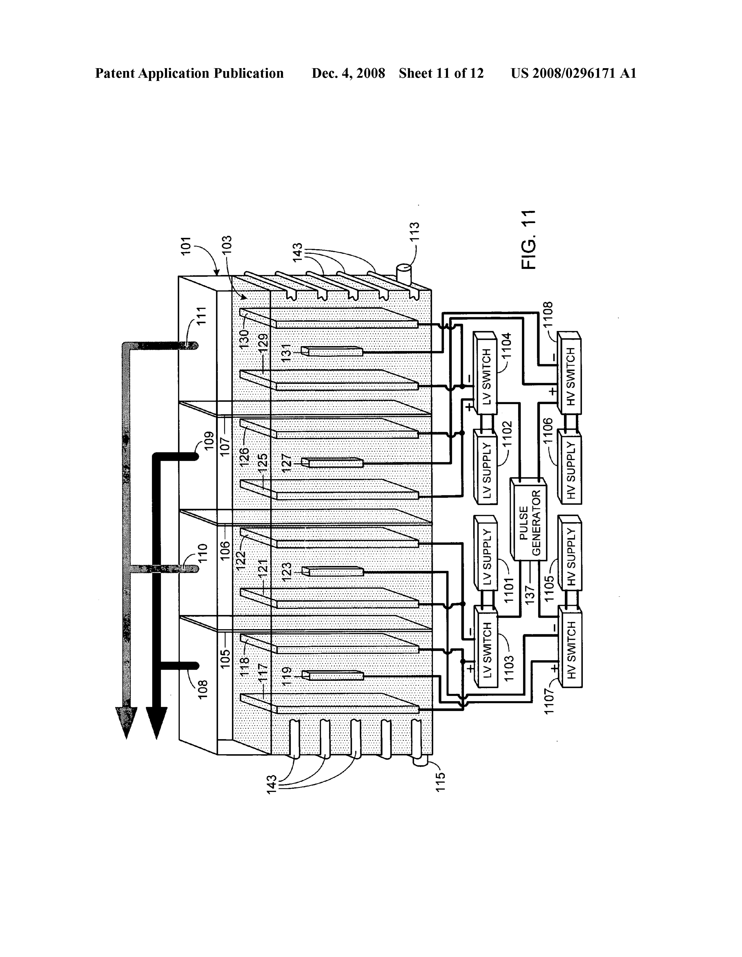
0047. It should be understood that the electrolysis system temperature). Alternately the initial period of time can simply of the present invention can be operated in a number of be a predetermined time period, for example 6 hours. modes, the primary differences between modes being the 0052. After the initial time period is exceeded, the system degree of process optimization used during operation. For output (e.g., temperature rate increase, steady state tempera example, FIG. 8 illustrates one method of operation requiring ture, etc.) is monitored (step 917) while optimizing one or minimal optimization. As illustrated, initially the electrolysis more of the operational parameters. Although the order of tank, e.g., tank 101, is filled with water (step 801). Preferably parameter optimization is not critical, in at least one preferred the level of water in the tank at least covers the top of the embodiment the first parameter to be optimized is pulse dura electrodes. The electrolyte can either be mixed into the water tion (step 919). Then the pulse frequency is optimized (step prior to filling the tank or after the tank is filled. The frequency 920), followed by optimization of the low voltage (step 921) of the pulse generator is then set (step 803) as well as the pulse and the high voltage (step 922). In this embodiment after duration (step 805). The initial voltage settings for the low optimization is complete the electrolysis process is allowed to Voltage power Supply and the high Voltage power Supply are continue (step 923) without further optimization until the also set (step 807). It will be appreciated that the order of process is halted, step 925. In another, and preferred, alterna set-up is clearly not critical to the electrolysis process. Typi tive approach illustrated in FIG. 10, one or more of optimi cally, prior to the initiation of electrolysis, the temperature of zation steps 919-922 are performed continuously throughout the water is at room temperature. the electrolysis process until electrolysis is suspended. 0048. Once set-up is complete, electrolysis is initiated 0053. Note that the optimization processes described rela (step 809). During the electrolysis process (step 811), and as tive to FIGS. 9 and 10 assume that (i) the cells physical previously noted, the water is heated by the process itself. geometry is fixed and (ii) there is no control over the low Eventually, when operation is no longer desirable, the elec and/or high voltage applied to individual cell electrodes. If the trolysis process is suspended (step 813). If desired, prior to system does include means for adjusting the physical geom further operation the tank can be drained (step 815) and etry of the individual cells during electrolysis, for example the refilled (step 817). Prior to refilling the tank, a series of spacing between the electrodes within the cells or the cell-to optional steps can be performed. For example, the tank can be cell spacing, these parameters can also be altered to further washed out (optional step 819) and the electrodes can be optimize the electrolysis process during system operation. cleaned, for example to remove oxides, by washing the elec The system can also be configured to provide additional con trodes with diluted acids (optional step 821). Spent, or used trol over the low and/or high voltage applied to the cells. For up, electrodes can also be replaced prior to refilling (optional example, the system shown in FIG. 11 uses a pair of low step 823). After cleaning the system and/or replacing elec voltage power supplies 1101/1102 and associated low voltage trodes as deemed necessary, and refilling the system, the switches 1103/1104, and a pair of high voltage power sup system is ready to reinitiate the electrolysis process. plies 1105/1106 and associated high voltage switches 1107/ 0049. The above sequence of processing steps works best 1108. Systems such as these, although more complex, pro once the operational parameters have been optimized for a vide further control and therefore potentially greater specific system configuration since the system configuration optimization.
will impact the heat generation efficiency of the process. 0054 The optimization process described relative to Exemplary system configuration parameters that affect the FIGS. 9 and 10 can be performed manually. In the preferred optimal electrolysis settings include tank size, quantity of embodiment, however, the system or portions of the system water, type and/or quality of water, electrolyte composition, are controlled via a system controller such as controller 1201 electrolyte concentration, electrode size, electrode composi shown in an alternate embodiment of the configuration illus tion, electrode shape, electrode configuration, electrode sepa trated in FIG. 1 (i.e., FIG. 12). Assuming that controller 1201 ration, cell number, cell separation, initial water temperature, is used to control and optimize the pulse frequency, pulse low Voltage setting, high Voltage setting, pulse frequency and duration, high Voltage and low Voltage, system controller pulse duration. 1201 is coupled to the pulse generator and the Voltage Sup 0050 FIG. 9 illustrates an alternate procedure, one in plies as shown. If the system controller is only used to control which the process undergoes optimization. Initially the tank and optimize a Subset of these parameters, the system con is filled (step 901) and initial settings for pulse frequency troller is coupled accordingly (i.e., coupled to the pulse gen (step 903), pulse duration (step 905), high voltage supply erator to control pulse frequency and duration; coupled to the output (step 907) and low voltage supply output (step 909) are high Voltage source to control the high Voltage; coupled to the made. Typically the initial settings are based on previous low Voltage source to control the low Voltage). In order to settings that have been optimized for a similarly configured allow optimization automation, system controller 1201 is also system. For example, assuming that the new configuration coupled to a system monitor, for example one or more tem was the same as a previous configuration except for the com perature monitors (e.g., monitor 1203). In at least one pre position of the electrodes, a reasonable initial set-up would be ferred embodiment system controller 1201 is also coupled to the optimized set-up from the previous configuration. a monitor 1205, monitor 1205 providing either the pH or the 0051. After the initial set-up is completed, electrolysis is resistivity of liquid 103 within electrolysis tank 101, thereby initiated (step 911) and system output is monitored (step 913), providing means for determining when additional electrolyte for example absolute temperature or the rate of temperature needs to be added. In at least one preferred embodiment increase. Although system optimization can begin immedi system controller 1201 is also coupled to a liquid level moni ately, preferably the system is allowed to run for an initial tor 1207, thereby providing means for determining when period of time (step 915) prior to optimization. The initial additional water needs to be added to the electrolysis tank. period of operation can be based on achieving a predeter Preferably system controller 1201 is also coupled to one or mined output, for example a specific level of temperature more flow valves 1209 which allow water, electrolyte, or a increase, or achieving a steady state output (e.g., steady state combination of water and electrolyte to be automatically
Page 19
US 2008/0296.171 A1 Dec. 4, 2008
added to the electrolysis system in response to pH/resistivity medium, wherein a portion of said conduit is in thermal data provided by monitor 1205 (i.e., when the monitored communication with at least a portion of said electrolysis pH/resistivity falls outside of a preset range) and/or liquid tank.
level data provided by monitor 1207 (i.e., when the monitored 5. The electrolysis system of claim 1, further comprising a liquid level falls below a preset value). liquid within said electrolysis tank, wherein said liquid 0055 As will be understood by those familiar with the art, includes at least one of water, deuterated water, tritiated the present invention may be embodied in other specific water, semiheavy water, heavy oxygen water, water contain forms without departing from the spirit or essential charac ing an isotope of hydrogen, or water containing an isotope of teristics thereof. Accordingly, the disclosures and descrip OXygen.
tions herein are intended to be illustrative, but not limiting, of 6. The electrolysis system of claim 5, further comprising an the scope of the invention which is set forth in the following electrolyte within said liquid, said electrolyte having a con claims. centration of between 0.05 and 10.0 percent by weight. 7. The electrolysis system of claim 1, wherein said first low
What is claimed is: Voltage anode is comprised of a first material, wherein said 1. An electrolysis system comprising: second low Voltage anode is comprised of a second material, an electrolysis tank; wherein said first low voltage cathode is comprised of a third a plurality of electrolysis cells within said electrolysis tank, material, wherein said second low Voltage cathode is com each of said plurality of electrolysis cells comprising: prised of a fourth material, wherein said first high voltage a membrane dividing said electrolysis cell into a first anode is comprised of a fifth material, wherein said first high region and a second region, wherein said membrane Voltage cathode is comprised of a sixth material, and wherein permits ion and electron exchange between said first said first, second, third, fourth, fifth and sixth materials are and second regions; selected from the group consisting of steel, nickel, copper, iron, stainless steel, cobalt, manganese, Zinc, titanium, plati a plurality of low voltage electrodes, said plurality of num, palladium, aluminum, lithium, magnesium, boron, car low voltage electrodes comprised of at least a first low bon, graphite, carbon-graphite, metal hydrides and alloys of Voltage anode and at least a second low Voltage anode steel, nickel, copper, iron, stainless steel, cobalt, manganese, contained within said first region, and said plurality of Zinc, titanium, platinum, palladium, aluminum, lithium, mag low voltage electrodes comprised of at least a first low nesium, boron, carbon, graphite, carbon-graphite and metal Voltage cathode and at least a second low voltage hydrides.
cathode contained within said second region; and 8. The electrolysis system of claim 1, wherein said plurality a plurality of high Voltage electrodes, said plurality of of low voltage electrodes are comprised of a first material, high Voltage electrodes comprised of at least a first wherein said plurality of high Voltage electrodes are com high Voltage anode contained within said first region prised of a second material, and wherein said first and second and interposed between said first low Voltage anode materials are selected from the group consisting of steel, and said second low Voltage anode, and said plurality nickel, copper, iron, stainless steel, cobalt, manganese, Zinc, of high Voltage electrodes comprised of at least a first titanium, platinum, palladium, aluminum, lithium, magne high Voltage cathode contained within said second sium, boron, carbon, graphite, carbon-graphite, metal region and interposed between said first low voltage hydrides and alloys of Steel, nickel, copper, iron, stainless cathode and said second low Voltage cathode: steel, cobalt, manganese, Zinc, titanium, platinum, palladium, a low Voltage source with a first output Voltage electrically aluminum, lithium, magnesium, boron, carbon, graphite, car connected to said plurality of low voltage electrodes of bon-graphite and metal hydrides.
each electrolysis cell; 9. The electrolysis system of claim 1, wherein said specific a high Voltage source with a second output Voltage electri pulse duration is between 0.01 and 75 percent of a time period cally connected to said plurality of high Voltage elec defined by said specific frequency.
trodes of each electrolysis cell, wherein said second 10. A method of operating a multi-cell electrolysis system output Voltage is higher than said first output Voltage; comprising the steps of and applying a low Voltage to at least a first low Voltage anode, means for simultaneously pulsing said low Voltage source a second low Voltage anode, a first low Voltage cathode and said high Voltage source at a specific frequency and and a second low Voltage cathode contained within each a specific pulse duration. of a plurality of electrolysis cells contained within an 2. The electrolysis system of claim 1, further comprising a electrolysis tank of said electrolysis system, said low system controller coupled to said electrolysis system, Voltage applying step further comprising the step of wherein said system controller is coupled to at least one of pulsing said low Voltage at a first frequency and with a said low Voltage source, said high Voltage source, said simul first pulse duration; and taneous pulsing means, a temperature monitor contained applying a high Voltage to at least a first high Voltage anode within said electrolysis tank, a pH monitor contained within and a first high Voltage cathode contained within each of said electrolysis tank, a resistivity monitor contained within said plurality of electrolysis cells, said high Voltage said electrolysis tank, a liquid level monitor contained within applying step further comprising the step of pulsing said said electrolysis tank, and a flow valve within an inlet line high Voltage at said first frequency and with said first coupled to said electrolysis tank. pulse duration, wherein said high Voltage pulsing step is 3. The electrolysis system of claim 1, further comprising performed simultaneously with said low Voltage pulsing means for cooling said electrolysis system. step, and wherein said first high Voltage anode is inter 4. The electrolysis system of claim3, wherein said cooling posed between said first low Voltage anode and said means is comprised of a conduit containing a heat transfer second low Voltage anode within a first region of each of
Page 20
US 2008/0296.171 A1 Dec. 4, 2008
said plurality of electrolysis cells, and wherein said first adding electrolyte to said liquid when said monitored pH high voltage cathode is interposed between said first low fails outside of a preset range. Voltage cathode and said second low Voltage cathode 16. The method of claim 11, further comprising the steps within a second region of each of said plurality of elec of:
trolysis cells. monitoring resistivity of said liquid within said electrolysis 11. A method of operating an electrolysis system compris tank; and ing the steps of adding electrolyte to said liquid when said monitored resis positioning a plurality of electrolysis cells within an elec tivity falls outside of a preset range. trolysis tank, wherein each of said electrolysis cells is 17. The method of claim 11, further comprising the steps
comprised of a membrane dividing each of said elec fabricating said plurality of low Voltage electrodes from a trolysis cells into a first region and a second region; first material;
filling said electrolysis tank with a liquid; fabricating said plurality of high Voltage electrodes from a positioning a plurality of low Voltage electrodes within second material; and each of said plurality of electrolysis cells, wherein said selecting said first material and said second material from plurality of low voltage electrodes is comprised of at the group consisting of steel, nickel, copper, iron, stain least a first low Voltage anode, a second low Voltage less steel, cobalt, manganese, Zinc, titanium, platinum, anode, a first low Voltage cathode and a second low palladium, aluminum, lithium, magnesium, boron, car Voltage cathode, wherein said positioning step further bon, graphite, carbon-graphite, metal hydrides and comprises the steps of positioning said first and second alloys of steel, nickel, copper, iron, stainless steel, low Voltage anodes within said first region of each of cobalt, manganese, Zinc, titanium, platinum, palladium, said electrolysis cells and positioning said first and sec aluminum, lithium, magnesium, boron, carbon, graph ond low Voltage cathodes within said second region of ite, carbon-graphite and metal hydrides. each of said electrolysis cells; 18. The method of claim 11, further comprising the steps positioning a plurality of high Voltage electrodes within of:
each of said plurality of electrolysis cells, wherein said fabricating said first low Voltage anode from a first mate plurality of high Voltage electrodes is comprised of at least a first high Voltage anode and a first high Voltage rial;
cathode, wherein said positioning step further comprises fabricating said second low Voltage anode from a second the steps of positioning said first high Voltage anode material;
between said first and second low Voltage anodes within fabricating said first low Voltage cathode from a third mate said first region of each of said electrolysis cells and rial;
positioning said first high Voltage cathode between said fabricating said second low Voltage cathode from a fourth first and second low Voltage cathodes within said second material;
region of each of said electrolysis cells; fabricating said first high Voltage anode from a fifth mate applying a low Voltage to said plurality of low Voltage rial;
electrodes, said low Voltage applying step further com fabricating said first high Voltage cathode from a sixth prising the step of pulsing said low Voltage at a first material; and frequency and with a first pulse duration; and selecting said first, second, third, fourth, fifth and sixth applying a high Voltage to said plurality of high Voltage materials from the group consisting of steel, nickel, cop electrodes, said high Voltage applying step further com per, iron, stainless steel, cobalt, manganese, Zinc, tita prising the step of pulsing said high Voltage at said first nium, platinum, palladium, aluminum, lithium, magne frequency and with said first pulse duration, and wherein sium, boron, carbon, graphite, carbon-graphite, metal said high Voltage pulsing step is performed simulta hydrides and alloys of steel, nickel, copper, iron, stain neously with said low Voltage pulsing step. less steel, cobalt, manganese, Zinc, titanium, platinum, palladium, aluminum, lithium, magnesium, boron, car 12. The method of claim 11, further comprising the step of bon, graphite, carbon-graphite and metal hydrides. selecting said liquid from the group consisting of water, deu 19. The method of claim 11, further comprising the step of terated water, tritiated water, semiheavy water, heavy oxygen selecting said first pulse duration to be between 0.01 and 75 water, water containing an isotope of hydrogen, or water percent of a time period defined by said first frequency. containing an isotope of oxygen. 20. The method of claim 11, further comprising the steps 13. The method of claim 11, further comprising the steps of:
of: monitoring a rate corresponding to said heat generation of monitoring a liquid level within said electrolysis tank; and said electrolysis system;
adding more of said liquid to said electrolysis tank when selecting an operating parameter from at least one of said said monitored liquid level falls below a preset value. low Voltage, said high Voltage, said first frequency, and 14. The method of claim 11, further comprising the step of said first pulse duration; and adding an electrolyte to said liquid. optimizing said operating parameter of said electrolysis 15. The method of claim 11, further comprising the steps system in response to said monitored heat generation of: rate.
monitoring pH of said liquid within said electrolysis tank;
and
Provenance
- Collection
- Patents citing this work
- Original assignee
- Kuzo Holding Inc
- Pages
- 20
- Method
- pdftotext (the PDF's own text layer) + pdftoppm 300dpi page scans
- Patent office record
- patents.google.com →
- Source
- Google Patents citing-documents table
- Inventors
- Nehemia Davidson; Kuzo Holding Inc
- Published
- 2008-12-04
- Transcribed from
- patentimages.storage.googleapis.com →