patent · US5154142
Ionic combustion system with ignitor assist
13 October 1992
Page 1 — bibliographic record
United States Patent (19) 11) Patent Number: 5,154,142 Kamo 45) Date of Patent: Oct. 13, 1992 54) IONIC COMBUSTION SYSTEM WITH 4,538,582 9/1985 Wakata ................................ 123/536 GNITOR ASSIST 4,552,106 11/1985 Spence ......... ... 123/25 D 5,012,772 5/1991 Nakamura ... 123/25 D (75) Inventor: Roy K. Kamo, Columbus, Ind. 5,076,246 12/1991 Onyszczuk ...... ... 123/538 (73) Assignee: Adiabatics, Inc., Columbus, Ind. Primary Examiner-E. Rollins Cross (21) Appl. No.: 855,261 Assistant Examiner-Erick Solis 22) Filed: Mar. 23, 1992 Attorney, Agent, or Firm-Baker & Daniels (51) Int. C. ............ 0 0 10 10 w av4 wwwP a a aw FO2B 47/O2
(52) U.S. Cl. ............ - - - - - - - - - - - 123/25 F; 123/1 A; An ionic combustion system for a heat engine having a 123/536; 123/25 B combustion chamber. A fuel source and water source 58) Field of Search a on so 123/25 R, 25 B, 25 D, are provided. An agitating chamber in fluid communi 123/25 E, 25 F, 1 A, 538, 536, 537, 23 cation with the water source has an agitator and at least 56) References Cited one magnetizing source for agitating and ionizing the
cated to a prechamber having a plurality of ignition 3,717, 129 2/1973 Fox ..................................... 23/ A assist rods adapted to heat the ionized water and fuel 4,355,969 10/1982 Nelson ................................ 123/536 and water prior to combustion.
4,368,711 i/1983 Allen ...... ... 123/25 B 4,463,708. 8/1984 Gerry .... ... 123/25 B 4,469,076 9/1984 Wolff .................................. 123/536 24 Claims, 8 Drawing Sheets
FUE
7. BNSW
Page 2
Drawing sheet — no readable text.
Page 3
Drawing sheet — no readable text.
Page 4
Drawing sheet — no readable text.
Page 5
Drawing sheet — no readable text.
Page 6
Drawing sheet — no readable text.
Page 7
Drawing sheet — no readable text.
Page 8
Drawing sheet — no readable text.
Page 9
Drawing sheet — no readable text.
Page 10
quickly heats the ionized fuel and/or water mixture
IONIC COMBUSTION SYSTEM WITH IGNITOR with a plurality of ignition assist rods prior to combus
Accordingly, the invention comprises, in one form,
FIELD OF THE INVENTION an ionic combustion system for an internal combustion The present invention relates to a heat piston engine engine. A fuel source and water source are provided. and, more particularly, to a system and method for An agitating chamber in fluid communication with the providing ionized water and fuel to a heat engine. fuel source and the water source has an agitator and at
BACKGROUND OF THE INVENTION
least one magnetizing source for respectively agitating 1O and ionizing a fuel and water mixture. A pre-chamber in
Systems to increase fuel efficiency and decrease pol fluid communication with the agitating chamber and lutant emissions from a heat engine, and more particu the combustion chamber has a plurality of ignition assist larly an internal combustion engine, are known in the rods adapted to heat the ionized fuel and water therein art. For example, U.S. Pat. No. 3,717,129 to Fox dis prior to combustion.
closes a method and apparatus for steam reforming a 5 The invention comprises, in another form thereof, an fuel for an internal combustion engine. A water and fuel ionic combustion system for an internal combustion mixture is passed through a catalytic converter where engine. A fuel source and a water source are provided. the mixture is heated by exhaust gases from the internal An agitating chamber has a first inlet adapted to receive combustion engine. The water in the water and fuel fuel from the fuel source, a said second inlet adapted to mixture, aided by a catalyst, is converted into steam receive water from the water source, and an outlet. The which reforms the fuel, thereby producing a reformed agitating chamber further includes an agitator for mix fuel with decreased pollutant properties when com ing the fuel and water in the agitating chamber and at busted.
Other systems employing application of a magnetic least fuel one magnetic field source adapted to ionize the and water mixture. The magnetic field source may field to a fuel are also known. For example, U.S. Pat. 25 be provided by a permanent magnetic or electromagnet Nos. 4,538,582 to Wakuta and 4,469,076 to Wolff both affixed to either the interior or exterior of the chamber. disclose systems for applying a magnetic field to a fuel A pre-chamber has an inlet in fluid communication with flowing into a combustion chamber of an internal com the agitating chamber outlet and an outlet in fluid com bustion engine. The magnetic field is believed to reduce munication with the combustion chamber. The pre the surface tension of the fuel and thereby increase fuel 30 chamber includes a plurality of ignition assist rods for oxidation.
Systems for increasing the efficiency of a heat engine heating the ionized fuel and water mixture. An advantage of the present invention is that the by providing an ionized fuel and water mixture to the water and/or water and fuel mixture is both ionized and combustion chamber are also known in the art. U.S. Pat.
No. 4,355,969 to Nelson, et al. discloses a method of 35 heated prior to combustion, thereby increasing fuel ionizing water and mixing the water with a fuel to form efficiency and decreasing pollutant emissions, including an emulsion which is introduced into a combustion hydrocarbons, carbon dioxide and smoke. chamber. The water is ionized prior to mixing with the Another advantage is that faster combustion, a higher fuel in an ionizer having a pair of electrically charged heat release rate, higher peak pressure, and greater plates. A high voltage power supply operating at a expansion of internal energy are achieved. voltage between 3 to 9 KV maintains the electrical Yet another advantage is that a combustion process charge in the plates for ionization of the water. Thus, having a shorter ignition delay period is achieved. the Nelson patent requires a high voltage to effect ioni A still further advantage is that the agitating impeller zation of the water. ensures adequate fluid flow past the permanent magnets It is also known to provide an internal combustion 45 and resultant ionization.
engine with ignitor assist rods to assist in more rapid BRIEF DESCRIPTION OF THE DRAWINGS combustion of introduced fuel.
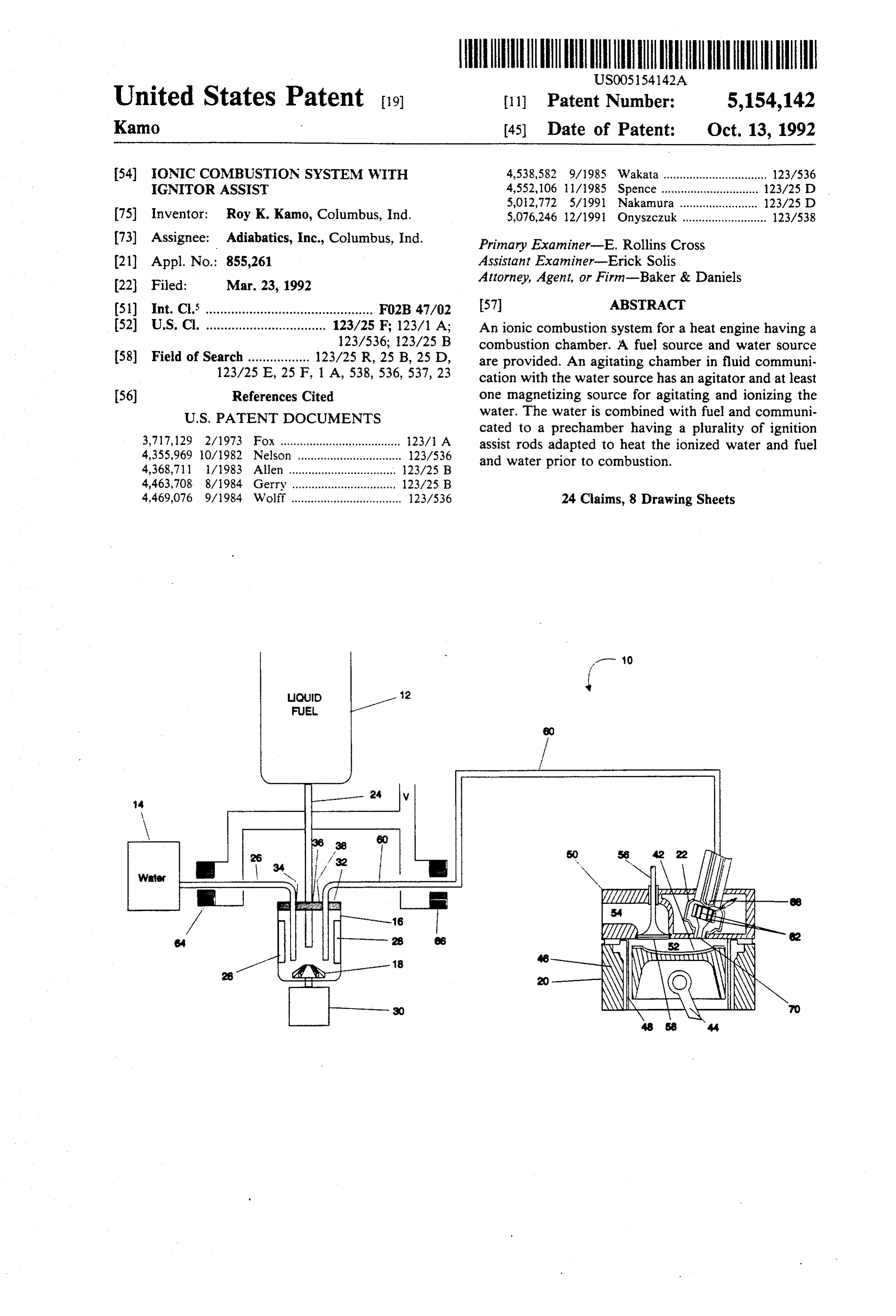
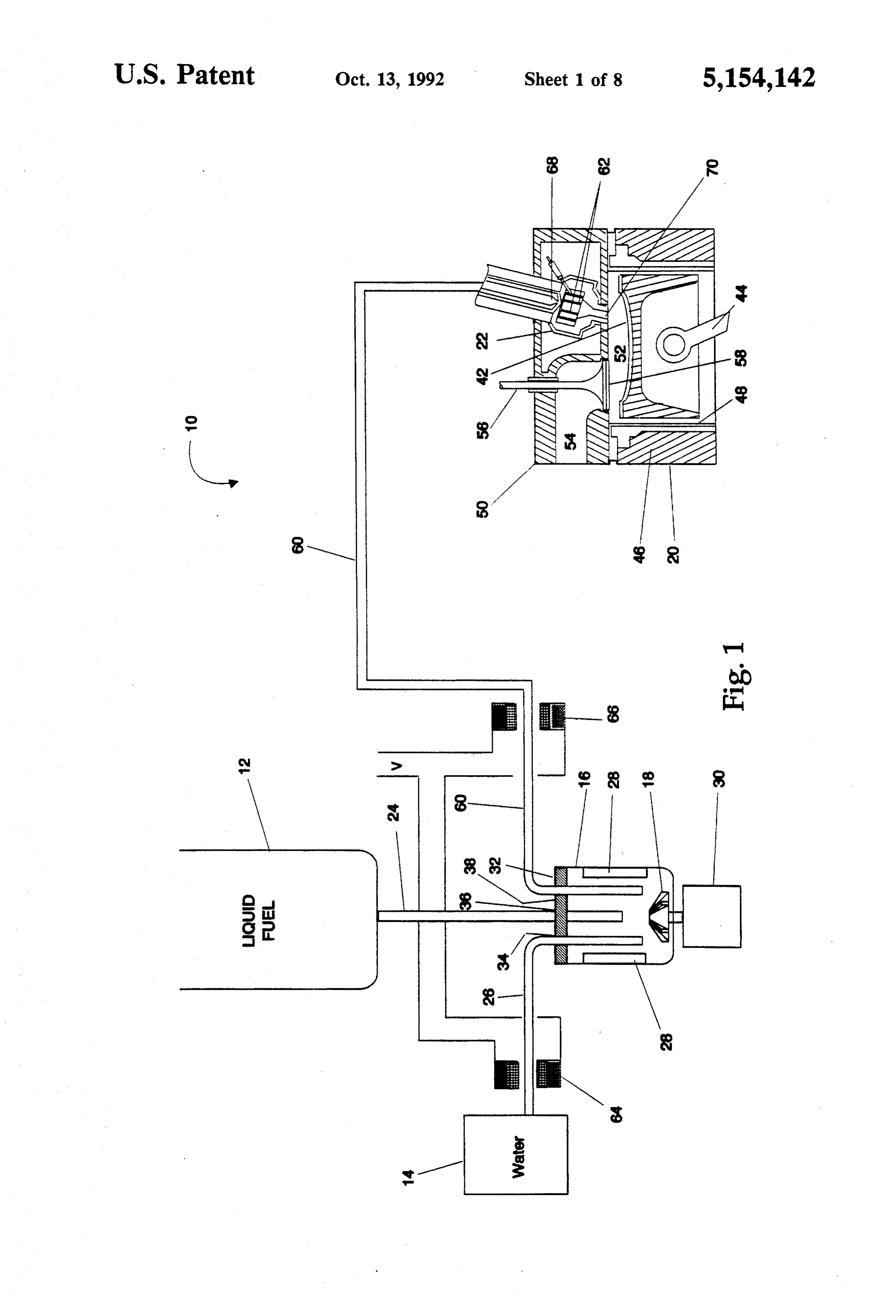
What is needed in the art is a system and method for The above-mentioned and other features and advan reliably and inexpensively providing an ionized fuel and tages of this invention, and the manner of attaining water mixture to a combustion chamber and enhancing SO then, will become more apparent and the invention will the physical properties of the ionized water and fuel be better understood by reference to the following de mixture in the combustion chamber prior to combus scription of embodiments of the invention taken in con tion. junction with the accompanying drawings, wherein: SUMMARY OF THE INVENTION FIG. 1 illustrates an ionic combustion system having 55 a liquid fuel source and a water source in fluid commu
The present invention provides an agitating chamber nication with an agitating chamber;
for ionizing a water and/or fuel and water mixture FIG. 2 shows an ionic combustion system having a which is in fluid communication with a pre-chamber fuel source with a slurried fuel and water mixture having a plurality of ignition assist rods for heating the therein which is in fluid communication with an agitat ionized mixture prior to combustion. ing chamber;
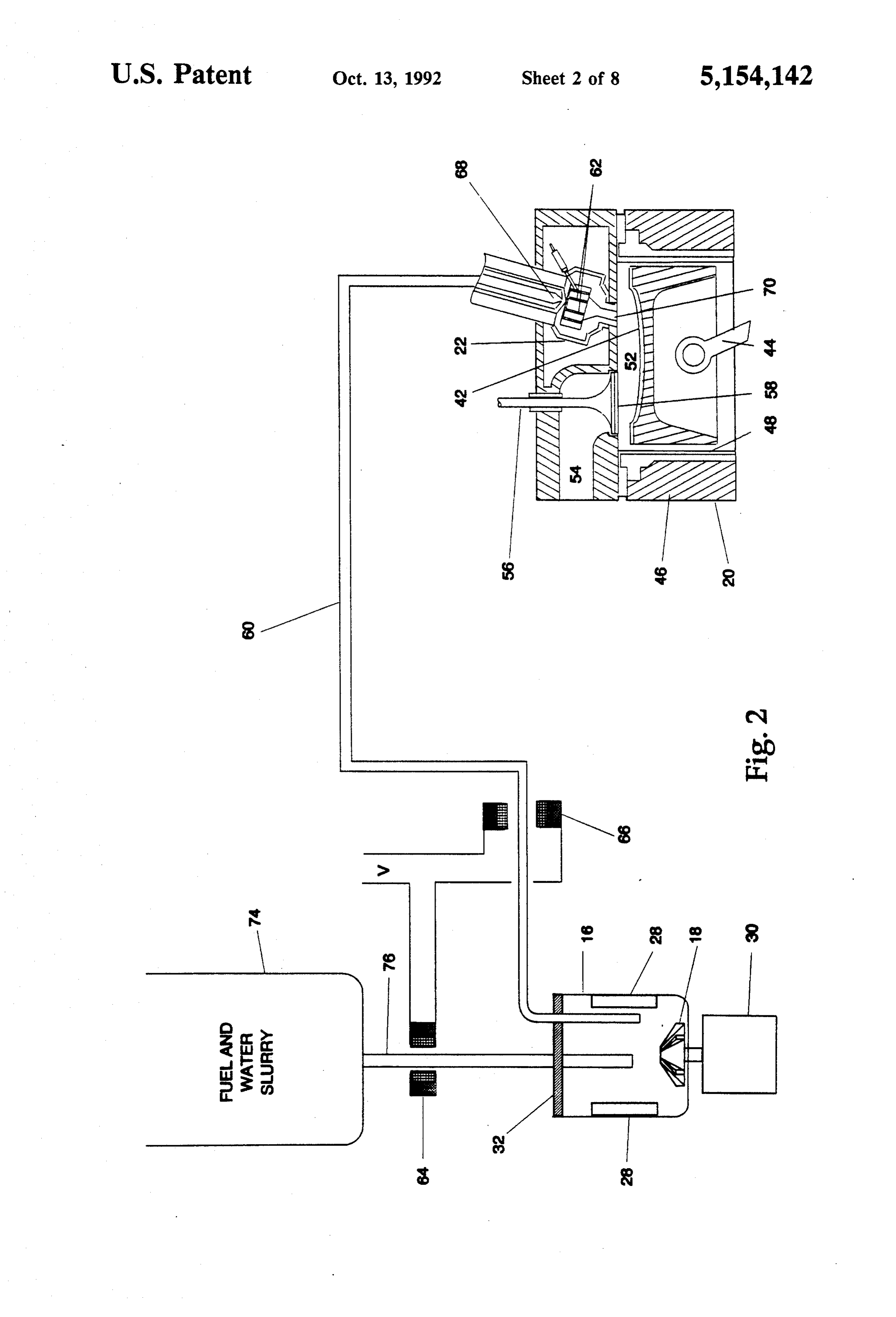
The agitating chamber may be adapted to receive the FIG. 3 depicts an ionic combustion system having a fuel and water as a slurry, to receive the fuel and water gaseous or solid fuel source in communication with a separately, or to receive water only. A rotating impeller pre-chamber and a water source in fluid communication agitates the fuel and/or water in the agitating chamber with an agitating chamber;
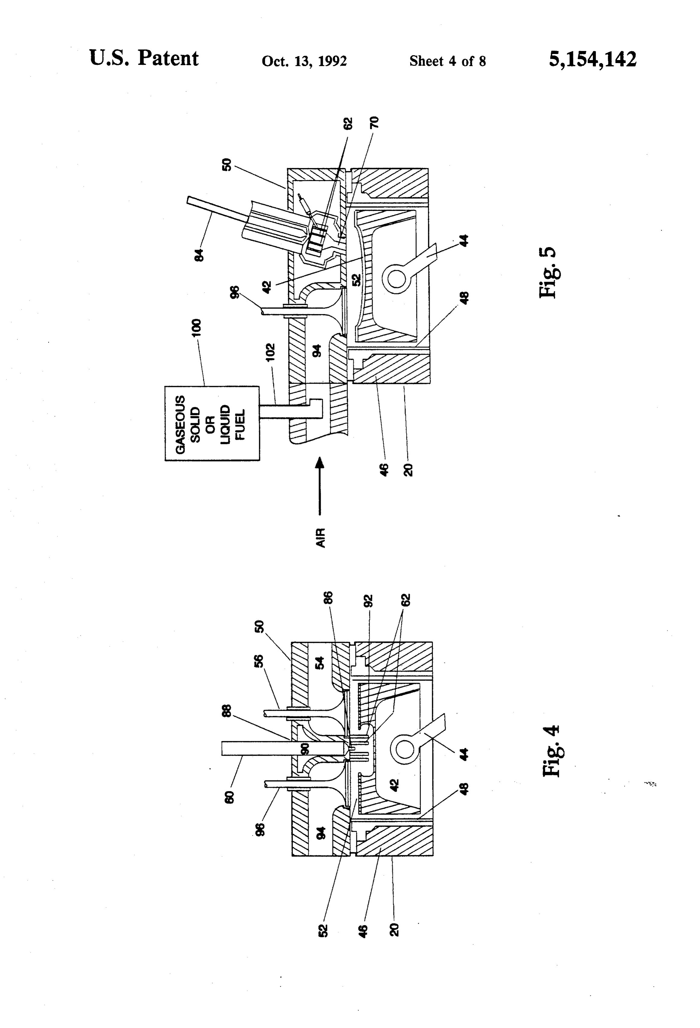
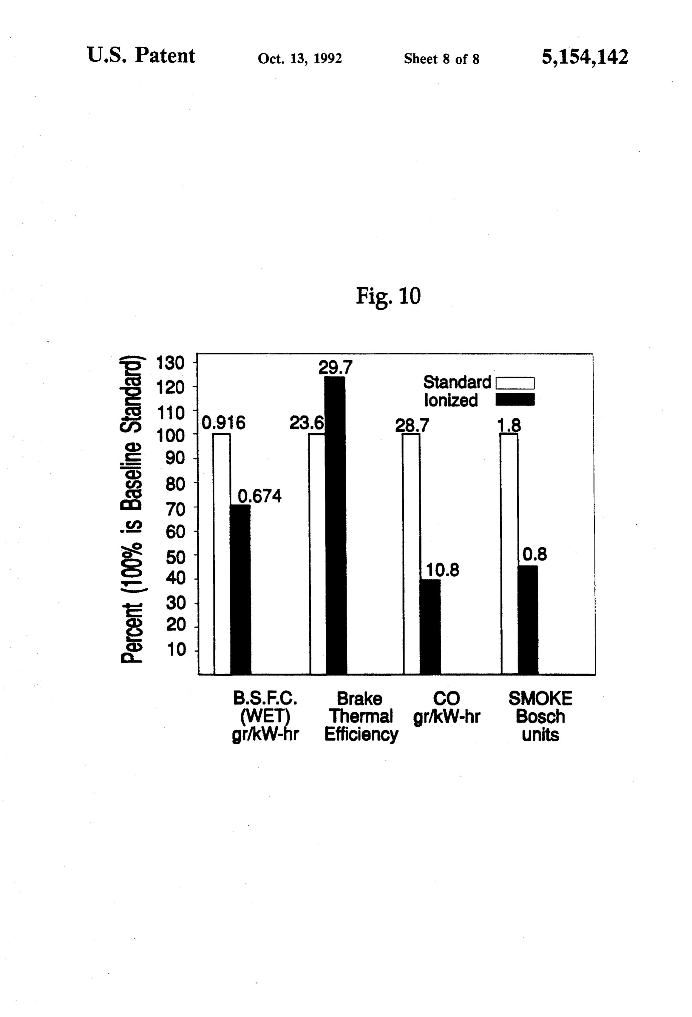
to cause fuel and/or water molecules to move past a 65 FIG. 4 shows an alternate embodiment of FIGS. 1-3 plurality of permanent magnets disposed within the wherein the plurality of ignition assist rods are adapted agitating chamber. The pre-chamber receives ionized to extend into the combustion chamber and a pre fuel and/or water from the agitating chamber and formed recess in the piston;
Page 11
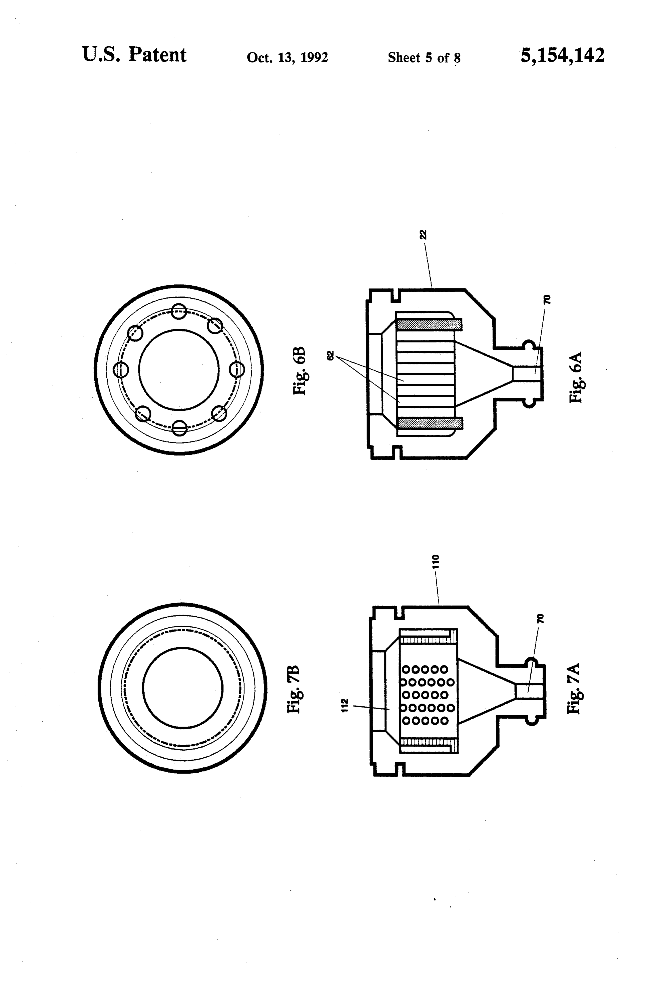
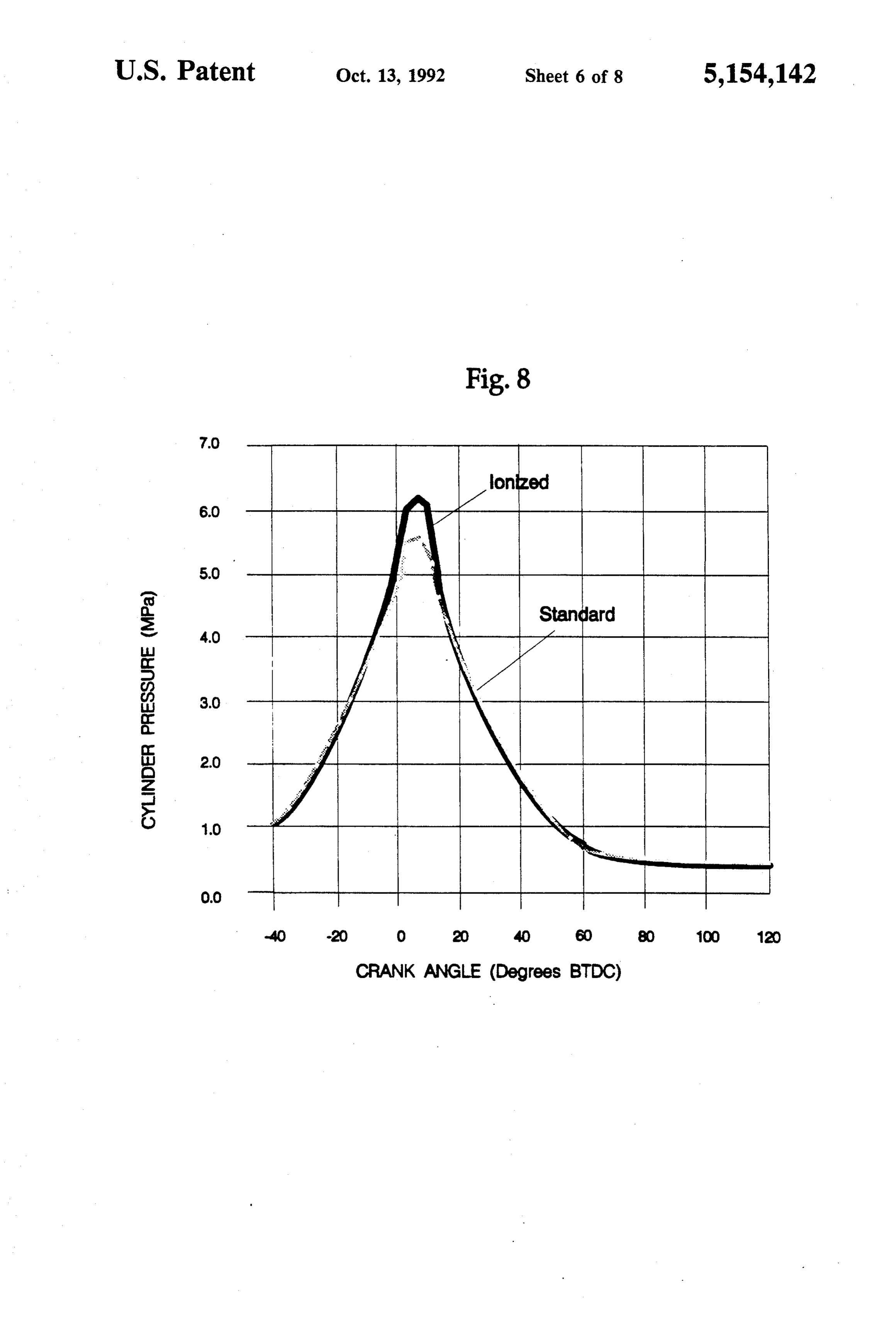
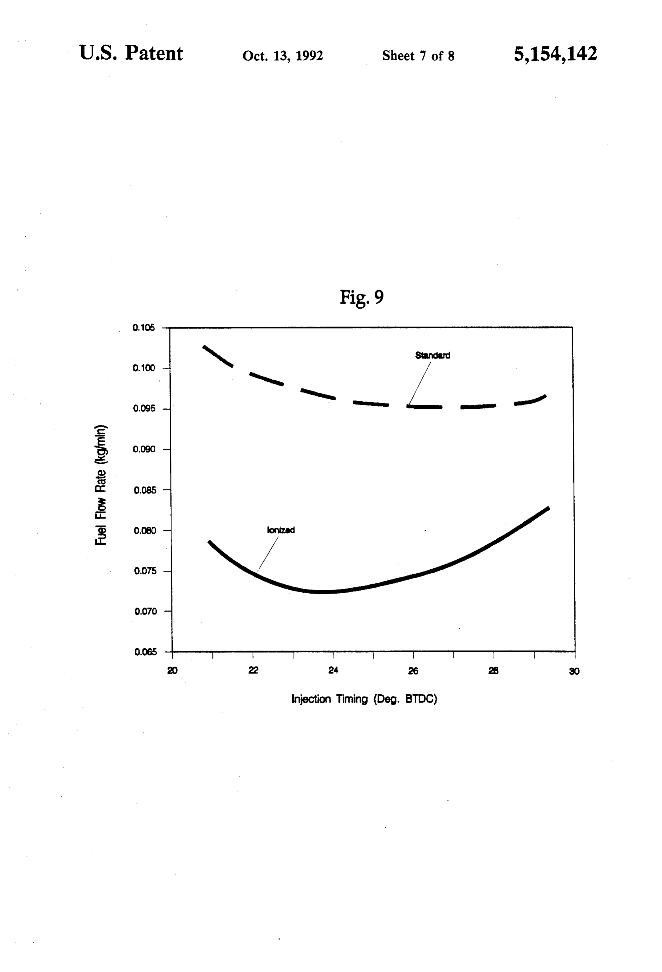
FIG. 5 is an alternate embodiment of FIGS. 1-3 to effectively carry out ionization of the fuel and water wherein the ionized water is introduced into the pre mixture. A lid member 32 is provided to prevent spill chamber and the fuel is introduced directly into the age of the liquid and fuel mixture during the agitation intake manifold; within agitating chamber 16 and is formed with first and FIGS. 6A and 6B respectively show a side sectional second inlets 34 and 36 for respectively receiving con view and a top view of an exemplary combustion cham duit mens 24 and 26, and an outlet 38 for receiving ber pre-chamber with a pin-rod type ignitor assist conduit means 40. Alternatively, impeller 18 may be which may be used with the present invention; connecting to a belt-driven pulley powered by any of a FIGS. 7A and 7B respectively show a side sectional number rotary apparatus on the engine. view and a top view of an exemplary combustion cham O Heat engine 20, such as an internal combustion en ber pre-chamber with a screen-type ignitor assist which gine, is of the type known in the art. Heat engine 20 may be used with the present invention; and includes a piston 42 having a piston rod 44 hingably FIG. 8 is a comparative graph showing increased connected thereto. Piston 42 is slidably carried within engine performance as represented by higher cylinder cylinder 46 having a cylinder lining 48. Fixed at the pressure using the system of the present invention. 15 upper end of cylinder 46 is a cylinder head 50 which FIG. 9 is a comparative graph showing reduced fuel coacts with piston 42 and cylinder 46 to form combus consumption using the system of the present invention. tion chamber 52 which volumetrically changes depend FIG. 10 is a comparative graph showing improved ing on the axial, position of piston 42 within cylinder 46. operating characteristics and reduced emissions using An exhaust manifold 54 is formed within cylinder the system of the present invention. 20 head 50 for exhausting combusted fuel and water from Corresponding reference characters indicate corre combustion chamber 52. Valve means 56 is slidably sponding parts throughout the several views. The ex carried within cylinder head 50 and has a generally emplification set out herein illustrates one preferred planar surface 58 forms a portion of combustion cham embodiment of the invention, in one form, and such ber 52. Valve means 56, as is known in the art, acts to exemplifications are not to be construed as limiting the 25 allow exhaust gas to be expelled from combustion scope of the invention in any manner. chamber 52 during a pre-determined period of the com OETAILED DESCRIPTION OF THE bustion process.
Formed within cylinder head 50 and supplying an
INVENTION ionized fuel and water mixture to combustion chamber Referring now the drawings and particularly to FIG. 30 52 is a prechamber 22 which is in fluid communication 1, there is shown one embodiment of the present inven with outlet 38 of agitating chamber 16 via a conduit tion. In general, ionic combustion system 10 includes a means 60. Prechamber 22 includes a plurality of ignitor liquid fuel source 12 having liquid fuel therein, a water assist means, such as, ignition assist rods 62, for further source 14 having water therein, an agitating chamber 16 enhancing the combustion of the fuel and water mixture having an agitator 18, and a heat engine 20 having a 35 within combustion chamber 52. Ignition assist rods 62 pre-chamber 22. are formed from a material capable of receiving heat More particularly, liquid fuel source 12 has therein a from the combustion of the fuel and water mixture combustible liquid fuel, such as gasoline or diesel fuel, within combustion chamber 52 and transferring the heat and is in fluid communication with agitating chamber 16 to the fuel and water mixture passing through precham via a conduit means 24. Water source 14 includes ber 22. In the embodiment shown, ignition assist rods 62 therein water which is transported into agitating cham are formed from tungsten but could be formed from any ber 16 via conduit means 26. other suitable material known in the art. In the embodiment shown in FIG. 1, fuel in liquid To further assist ionization of the water and water fuel source 12 and water in water source 14 are urged and fuel mixture, electro-magnets 64 and 66 are pro by gravitational force through conduits 24 and 26 re 45 vided. Electro-magnets 64 and 66 may be connected in spectively and into agitating chamber 16. In an alterna series, as shown in FIG. 1, with a voltage differential tive embodiment, liquid fuel source 12 and water source (V) applied to the circuit. Electro-magnet 64 is disposed 14 may be pressurized to further aid in transporting around the circumference of conduit means 26 and liquid fuel and water respectively into agitating cham operates to assist ionization of water transported ber 16. Moreover, liquid fuel source 12 and water 50 through conduit means 26 to agitating chamber 16. source 14 may include, as is known in the art, metering Similarly, electro-magnet 66 is disposed around the or valving apparatus to control the flow rate of liquid circumference of conduit means 60 and operates to fuel to agitating chamber 16. further ionize the fuel and water mixture transported Agitating chamber 16 is adapted to mix and ionize from agitating chamber 16 to prechamber 22 via con liquid fuel and water supplied by liquid fuel source 12 55 duit means 60.
and water source 14. Accordingly, agitating chamber During operation, liquid fuel and water are trans 16 includes an agitator 18 which is connected to and ported respectively from liquid fuel source 12 and water rotatably driven by an electric motor 30. In the embodi source 14 into agitating chamber 16. A portion of the ment shown, agitator 18 is an impeller which imparts water passing through conduit means 26 from the water rotary motion to the liquid fuel and water within agitat source 14 to the agitating chamber 16 is ionized by ing chamber 16. A pair of permanent magnets 28 are electromagnet 64. Rotating impeller 18 acts to mix the provided to ionize the fuel and water mixture within fuel and water mixture within agitating chamber 16 and agitating chamber 16 and thereby improve the combus further acts to radially displace the fuel and water mix tion of the fuel and water mixture within heat engine 20. ture towards the permanent magnets 28. Permanent Alternatively, the magnetic field may be provided by a 65 magnets 28 function to further ionize the fuel and water permanent or electro magnet located either outside or mixture within agitating chamber 16. The mixed and inside the agitating chamber. A different number of ionized fuel and water is transported through the agitat permanent magnets, e.g., 1,3 or 4 may also be employed ing chamber outlet 38 via a conduit means 62 to inlet 68
Page 12
of prechamber 22. Electromagnet 66 functions to fur The embodiment shown in FIG. 4 operates as fol ther ionize the fuel and water mixture passing through lows: an ionized fuel and water mixture is transported conduit means 60. The mixture passing through pre through conduit means 60 and passageway 90 to injec chamber 22 flows past a plurality of hot ignition assist tor port 86. The ionized fuel and water mixture is in rods 62 and is heated and ignited thereby. The heated 5 jected into combustion chamber 52 and heated and and ignited fuel and water mixture is then transported ignited by the plurality of ignition assist rods 62 for through the prechamber outlet 70 and into main com further enhancing the combustion process. Intake valve bustion chamber 52. Simultaneously, air is transported means 96 is operated and moves downwardly into com into the combustion chamber through an intake mani bustion chamber 52, thereby allowing intake air to flow fold and intake valve means (not shown). The fuel and 10 through intake manifold 94 into combustion chamber 52 water mixture is then combusted within combustion where the air is mixed with the heated and ionized fuel chamber 52 and thereby forces piston 42 to move down and water mixture. The heated and ionized fuel and ward away from cylinder head 50. Exhaust valve means water and air mixture is combusted within combustion 56 is operated and moves downward allowing the com chamber 52, thereby exerting downwardly force against busted exhaust gas to be transported through the ex 15 piston 42 causing the piston to move away from top haust manifold 54 to the environment. dead center. Exhaust valve means 56 is operated to FIG. 2 illustrates an embodiment of the present in move downwardly within combustion chamber 52 and vention wherein a fuel and water slurry may be supplied the combusted exhaust gas is transported to exhaust to the agitating chamber 16. The fuel is typically a solid manifold 54.
fuel, such as coal, which is ground into a fine powder 20 FIG. 5 depicts an embodiment of the present inven and mixed with water to form a fuel and water slurry. In tion wherein a fuel is injected into an intake manifold 94 the embodiment shown, a slurried fuel and water source and ionized water is transported into a prechamber 22. 74 has a fuel and water slurry therein which is trans The fuel received from a fuel source 100 via conduit ported to the agitating chamber 16 via conduit means means 102 may be of a gaseous, solid or liquid type. The 76. An electromagnet 64 is disposed around the circum 25 fuel is injected into the intake manifold, as is known in ference of conduit means 76 and functions to partially the art, and flows into combustion chamber 52 when ionize the fuel and water slurry transported through intake valve means 96 is in a downward, open position. conduit means 76. During the compression stroke of the piston, the fule is FIG. 3 illustrates another embodiment of the inven displaced into the prechamber 22. Injection timed ion tion wherein a gaseous or solid fuel source 80 directly 30 ized water is transported through conduit means 84 and supplies fuel to prechamber 22 where the fuel is simulta into prechamber 22 where the ionized water and the neously mixed with ionized water. Because the water is fuel is heated and ignited by ignition assist rods 62. The a better conductor than the fuel, the water may be ion heated and ionized water is then transported through ized in agitating chamber 16 prior to mixing with the prechamber outlet 70 and into combustion chamber 52 fuel in prechamber 22. 35 where it is mixed with fuel received through intake A water source 14 includes water therein which is manifold 94. The ionized water, fuel and air mixture is transported via conduit means 26 to agitating chamber combusted within combustion chamber 52 and expelled 16. Impeller 18 causes the water to be radially displaced through an exhaust manifold (not shown). towards permanent magnets 28 which ionize the water. FIGS. 6A and 6B illustrate in greater detail a partial Moreover, agitation by the water of impeller 18 assures side view and top view of a prechamber 22 of the type that water molecules randomly pass close by permanent which may be used with the present invention. Pre magnets 28 and are thereby ionized. The ionized water chamber 22 has an ignitor assist comprising eight tung is transported via conduit means 84 to a second pre sten rods disposed therein for heating water or a fuel chamber inlet 82 of prechamber 22 and is injected into and water mixture which is subsequently injected into prechamber 22. The solid or gaseous fuel is mixed with 45 the combustion chamber 52. At the beginning of opera the ionized water within prechamber 22 and heated and tion of heat engine 20, ignition assist rods 62 are at or ignited by the plurality of ignition assist rods 62 before about an ambient temperature. Prechamber 22 is dis being transported through prechamber outlet 70 and posed within cylinder head 50 such that prechamber into combustion chamber 52 where the mixture is com outlet 70 is disposed at the bottom surface of cylinder busted. 50 head 50. Prechamber outlet 70 consists of an open pas FIG. 4 shows an alternative embodiment of the in sageway and therefore prechamber 22 is in fluid com vention shown in FIGS. 1-3 wherein the ionized water munication with combustion chamber 52. As fuel is and fuel mixture is injected directly into combustion combusted within combustion chamber 52, the heat chamber 52 (direct injection) and the plurality of igni caused by the combustion process increases the temper tion assist rods 62 extend into the direct injection com 55 ature of ignition assist rods 62 disposed within precham bustion chamber 52. Cylinder head 50 is formed to ber 22. After a certain amount of time, the ignition rods define an injector port 86 and a cylinder head inlet 88. will achieve a steady-state operating temperature attrib An ionized fuel and water mixture, such as shown in utable to the heat of the combustion process, Fueland FIGS. 1 or 2, is transported through conduit means 60 /or water which is injected into prechamber 22 will to cylinder head inlet 88. The ionized mixture is trans flow past the plurality of ignition assist rods 62 and ported through passageway 90 and injected through experience an increase in temperature due to heat trans injector port 86 into the combustion chamber 52. Igni fer from the ignition assist rods 62 to the fluid. This tion assist rods 62 are disposed adjacent to injector port increase in temperature, and the ionization of the water 86 and extend downwardly from the bottom surface of or fuel/water mixture, increases the combustion erff cylinder head 50. Piston 42 is formed with a recess 92 in 65 ciency of the fuel and decreases the ignition time and the upper surface thereof such that ignition assist rods delay time during the combustion process. The heated 62 extend into recess 92 when the piston 42 is at or about fuel and/or water is subsequently injected into combus top dead center. tion chamber 52.
Page 13
FIGS. 7A and 7B illustrate an alternative embodi cover any variations, uses, or adaptations of the inven ment of the present invention in which prechamber 110 tion using its general principals. Further, this applica is provided with a screen type ignitor assist. The func tion is intended to cover such departures from the pres tion of screen type ignitor assist shown in FIGS. 7A and ent disclosure as come within known or customary 7B is similar to the function of the rod type ignitor assist practice in the art to which this invention pertains and shown in FIGS. 6A and 6B. In the embodiment shown, which fall within the limits of the appended claims. fine-mesh metal 112 includes a plurality of small holes What is claimed is:
through which the water and/or fuel passes prior to 1. An ionic combustion system for a piston engine being injected into the combustion chamber 52. The having a combustion chamber, comprising: water and/or fuel flows through fine-mesh metal screen 10 a fuel source;
112 and is increased in temperature as a result of heat a water Source;
transfer between fine mesh metal screen 112 and the an agitating chamber comprising water and/or fuel. a first inlet and an outlet, the first inlet adapted to It will be appreciated to those of skill in the art that receive water from a water supply, many other forms of ignitor assist means may be em 15 an agitator for agitating water in the agitating ployed in lieu of the rod and screen types disclosed chamber, and above, provided such ignitor assist means has the ability at least one magnet field means adapted to ionize to store sufficient heat to assist in the ignition of the water in the agitating chamber; and ionized water and fuel mixture. wherein the combustion chamber comprises: FIG. 8 is a comparative graph showing increased 20 inlet means in fluid communication with the agitat engine performance using the system of the present ing chamber outlet and the fuel source outlet, - invention. The horizontal axis represents the crank and angle with zero (0) being at top dead center, and the an ignitor assist means for heating ionized water vertical axis represents cylinder pressure in megapas and fuel introduced from the combustion cham cals. The curves shown in FIG. 8 are illustrative of 25 ber inlet means.
results which may be obtained using a coal and water 2. The ionic combustion system of claim 1 wherein slurry in an embodiment such as shown in FIG. 2, on a the combustion chamber further comprises a pre-cham Caterpillar 1Y73 engine operating at 1,400 RPM with 6 ber, and wherein the ignitor assist means is within the kW output and ignition timing of 30 BTC (before top pre-chamber.
dead center). As indicated, a higher cylinder pressure, 30 3. The ionic combustion system of claim 1 wherein resulting in increased work by the engine, is achieved the combustion chamber inlet means comprises: using the system of the present invention. Moreover, a first inlet in fluid communication with the agitating the peak cylinder pressure occurs at a crank angle chamber outlet, which is closer to top dead center, thereby indicating a second inlet in fluid communication with the fuel decreased ignition delay of the fuel within combustion 35 SOCe.
chamber 52. 4. The ionic combustion system of claim 1 wherein FIG. 9 is a comparative graph showing decreased the agitating chamber further comprises a second inlet fuel (coal water slurry) consumption using a Caterpillar adapted to receive fuel from the fuel source. 1Y73 engine operating at 1,400 RPM and 30 ft. lb. 5. The ionic combustion system of claim 1 wherein torque, at various engine timings, for both a standard the fuel source and water source comprise a single ves system and an ionized system of the present invention. sel and are communicated to the agitating chamber by FIG. 10 is a comparative graph showing operating the first inlet.
characteristics and emissions using a Caterpillar 1Y73 6. The ionic combustion system of claim 1 wherein engine on coal water slurry running at 1,400 RPM, 6 the fuel source comprises a coal water slurry source. kW Output and at 23 BTDC injection timing. The 45 7. The ionic combustion system of claim 1 wherein 100% baseline graphs are for standard coal water slurry the fuel source comprises a gas fuel source. fuel without the invention, and the comparative graphs 8. The ionic combustion system of claim 1 wherein are for the same engine operating conditions but using the fuel source comprises a solid fuel source. the ionized system of the invention. The reductions in 9. The ionic combustion system of claim 1 wherein carbon monoxide (CO) and smoke are particularly nota 50 the agitator comprises a rotatable impeller extending ble. into the agitating chamber.
Diesel fuel combusted with non-ionized water re 10. The ionic combustion system of claim 1 wherein duces NOX drastically. Fifty percent water content can the at least one magnet field means comprises a perma reduce NOX by about sixty percent (60%). Coal water nent magnet.
slurry (CWS) is already mixed with water and NOX 55 11. The ionic combustion system of claim 1 further reduction is already great compared to any fuel not comprising an electro-magnet adapted to ionize the having water mixed therewith. Ionized CWS as de water flowing from the water source to the pre-cham scribed herein increases NOX somewhat because of ber.
more efficient combustion, and higher temperature. 12. The ionic combustion system of claim 11 wherein However, the NOX emissions using CWS and the pres 60 the electro-magnet is located between the agitating ent invention is still substantially lower than using a chamber and the combustion chamber. non-water containing fuel. 13. The ionic combustion system of claim 1 wherein While this invention has been described as having a the agitating chamber comprises an interior wall, and preferred design, the present invention can be further the at least one magnet field means is rigidly fixed to the modified within the spirit and scope of this disclosure. 65 interior wall of the agitating chamber. The terminology used in this disclosure is used for the 14. A method of operating an internal combustion purpose of illustration of the present invention and not piston engine having a combustion chamber compris for limitation. This application is therefore intended to 1ng:
Page 14
providing an ionic combustion system said ionic com 15. The method of claim 14 wherein the combustion bustion system comprising: chamber further comprises a pre-chamber, and wherein a fuel source; the ignitor assist means are within the pre-chamber. a water source; 16. The method of claim 14 wherein the ionized an agitating chamber comprising water and fuel are communicated to the combustion a first inlet and an outlet, the first inlet adapted to chamber by a combined combustion chamber inlet. 17. The method of claim 14 wherein the ionized receive water from a water supply, an agitator water and fuel are communicated to the combustion for agitating water in the agitating chamber, and chamber at least one magnet field means adapted to ionize 10 18. Thebymethod separate combustion chamber inlets. claim 14 further comprising the steps water in the agitating chamber; and wherein the of communicating fuel to the agitating chamber, and combustion chamber comprises: mixing the water and fuel together in the agitating inlet means in fluid communication with the agitat chamber.
ing chamber outlet and fuel source outlet, and 19. The method of claim 18 wherein the fuel source an ignitor assist means for heating ionized water 15 and water source comprise coal water slurry. and fuel introduced from the combustion cham 20. The method of claim 14 wherein the fuel source ber inlet means, comprises a gas fuel source.
introducing water into the agitating chamber, 21. The method of claim 14 wherein the fuel source agitating the water in the agitating chamber such that 20 comprises a solid fuel source. the water engages a magnetic field from the mag 22. The method of claim 14 wherein the agitating net field means to thereby ionize the water, chamber further comprises a rotatable impeller extend communicating the ionized water to the combustion ing23.intoThethemethod agitating chamber.
of claim 14 further comprising the chamber, step of passing the ionized water through a magnetic communicating fuel to the combustion chamber, 25 field when communicating it from the agitating cham directing the ionized water and fuel against the igni ber to the combustion chamber.
tor assist means to thereby heat and ignite the ion 24. The method of claim 14 wherein at least one per ized water and fuel, and manent magnet is rigidly fixed to the interior wall of the combusting the ionized and heated fuel and water agitating chamber.
mixture in the combustion chamber. 30 k : k
Provenance
- Collection
- Cited prior art
- Original PDF
- patentimages.storage.googleapis.com →
- Filed
- 1992-03-23
- Pages
- 14
- Method
- pdftotext (the PDF's own text layer) + pdftoppm 300dpi page scans
- Source
- Google Patents bibliographic record
- Granted
- 1992-10-13
- Inventors
- Roy K. Kamo; Adiabatics Inc
- Transcribed from
- patentimages.storage.googleapis.com →