patent · US5552675
High temperature reaction apparatus
3 September 1996
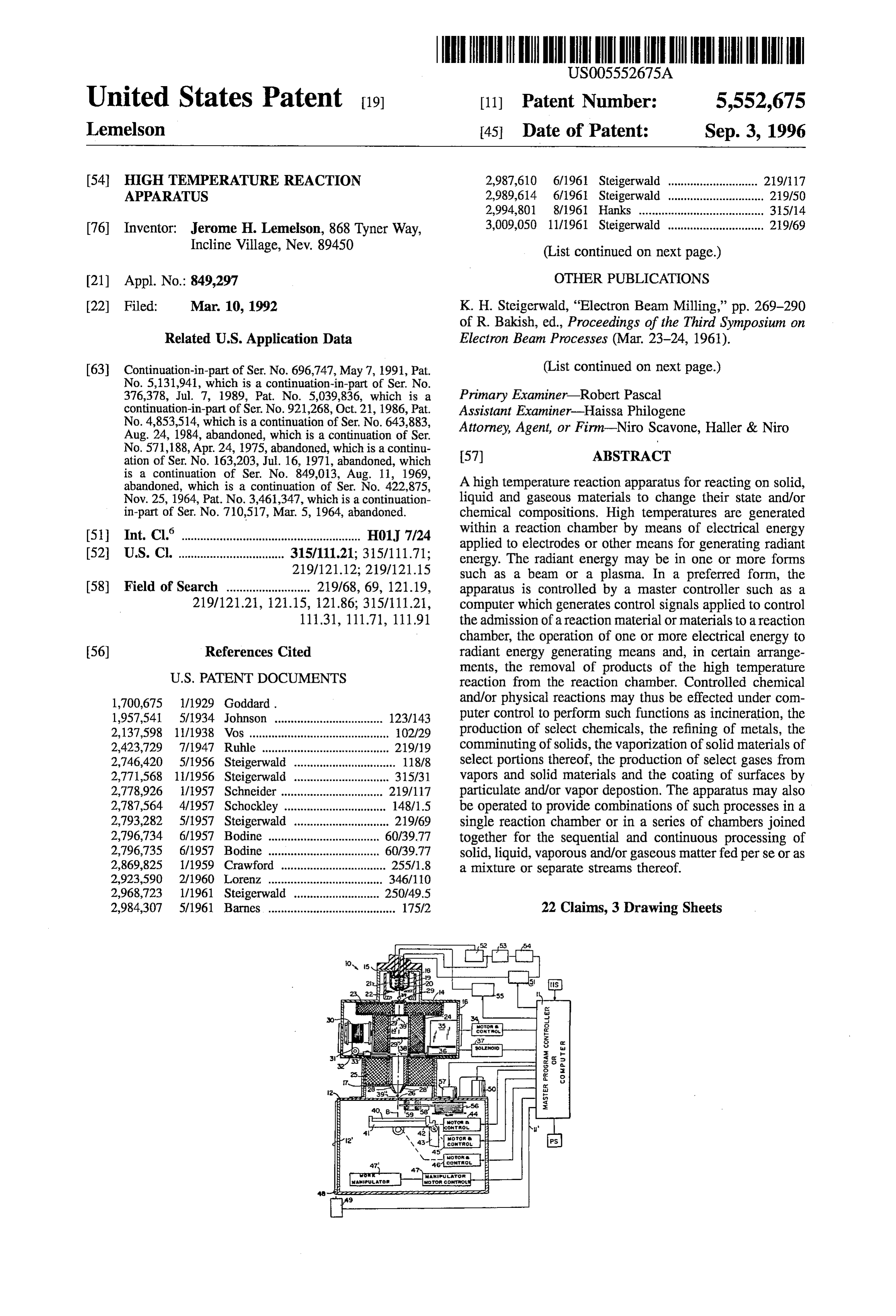
Page 1 — bibliographic record
IIIII
United States Patent 19 11 Patent Number: 5,552,675 Lemelson 45 Date of Patent: Sep. 3, 1996 (54) HIGH TEMPERATURE REACTION 2,987,610 6/1961 Steigerwald ............................ 219/117 APPARATUS 2,989,614 6/1961 Steigerwald ..... ... 219/50 2,994,801 8/1961 Hanks ....................................... 315/14 76 Inventor: Jerome H. Lemelson, 868 Tyner Way, 3,009,050 11/1961 Steigerwald .............................. 29/69 Incline Village, Nev. 89450 (List continued on next page.) (21) Appl. No. 849,297 OTHER PUBLICATIONS 22 Filed: Mar. 10, 1992 K. H. Steigerwald, “Electron Beam Milling,” pp. 269-290 of R. Bakish, ed., Proceedings of the Third Symposium on
Related U.S. Application Data Electron Beam Processes (Mar. 23–24, 1961). 63 Continuation-in-part of Ser. No. 696,747, May 7, 1991, Pat. (List continued on next page.) No. 5,131,941, which is a continuation-in-part of Ser. No.
376,378, Jul. 7, 1989, Pat. No. 5,039,836, which is a Primary Examiner Robert Pascal continuation-in-part of Ser. No. 921,268, Oct. 21, 2. Pat. Assistant Examiner-Haissa Philogene No. 4,853,514, which is a continuation of Ser. No. 643,883, irr-i-Ni
Aug. 24, 1984, abandoned, which is a continuation of Ser. Attorney, Agent, or Firm-Niro Scavone, Haller & Niro No. 571,188, Apr. 24, 1975, abandoned, which is a continu ation of set No. 163.203, ii.16, 1971, abandoned, which (57) ABSTRACT
abandoned, which is a continuation of Ser. No. 422,875, A high temperature reaction apparatus for reacting on solid, Nov. 25, 1964, Pat. No. 3,461,347, which is a continuation- liquid and gaseous materials to change their state and/or in-part of Ser. No. 710,517, Mar. 5, 1964, abandoned. chemical compositions. High temperatures are generated 6 within a reaction chamber by means of electrical energy (51 Int. Cl. ........................................................ H01, 7/24 applied to electrodes or other means for generating radiant 52 U.S. Cl. ................................. 315/111.21; 315/111.71; energy. The radiant energy may be in one or more forms 219/121.12; 219/121.15 such as a beam or a plasma. In a preferred form, the 58) Field of Search .......................... 219/68, 69, 121.19, apparatus is controlled by a master controller such as a 219/121.21, 121.15, 121.86; 315/111.21, computer which generates control signals applied to control 111.31, 111.71, 111.91 the admission of a reaction material or materials to a reaction chamber, the operation of one or more electrical energy to 56) References Cited radiant energy generating means and, in certain arrange ments, the removal of products of the high temperature
1,700,675 l/1929 Goddard. and/or physical reactions may thus be effected under com 1,957,541 5/1934 Johnson .................................. 123/143 puter control to perform such functions as incineration, the 2,137,598 11/1938 Vos ........ 102/29 production of select chemicals, the refining of metals, the 2,423,729 7/1947 Ruhle ........ ... 219/19 comminuting of solids, the vaporization of solid materials of 2,746,420 5/1956 Steigerwald .. ... 118/8 select portions thereof, the production of select gases from 2,771,568 11/1956 Steigerwald .. 315/31 vapors and solid materials and the coating of surfaces by 2,778,926 1/1957 Schneider ...... ... 219/17 particulate and/or vapor depostion. The apparatus may also 2,787,564 4/1957 Schockley ..... w 148/15 be operated to provide combinations of such processes in a 2,793,282 5/1957 Steigerwald .............................. 219/69 single reaction chamber or in a series of chambers joined 2,796,734 6/1957 Bodine ...... ... 60/39.77 together for the sequential and continuous processing of 2,796,735 6/1957 Bodine ...... ... 60/39.77 solid, liquid, vaporous and/or gaseous matterfed perse or as 2,869,825 1/1959 Crawford ................................. 255/18 a mixture or separate streams thereof. 2,923,590 2/1960 Lorenz ...... ... 346/110 2,968,723 1/1961 Steigerwald .. ... 250/49.5 2,984,307 5/1961 Barnes ........................................ 175/2 22 Claims, 3 Drawing Sheets
Page 2
5,170,032 12/1993 Lemelson ........................... 219/121.15 3,016,449 1/1962 Steigerwald .............................. 191117 5,231,259 7/1993 Lemelson ........................... 219/121.2 3,020,389 2/1962 Gorman .................................. 219/121 3,033,974 5/1962 Schleich et al. ........................ 219,117 OTHER PUBLICATIONS 3,067,572 2. Baumgartner ............................... 60/25 Crawford, "Electron Beam Machining,” chapter 11 of Bak 3,087,211 963 Howe ....................................... 22/57.2 3,112,850 12/1963 Garibotti ..................................... , ish, ed., Introduction to Electron Beam Technology (John 3,117,022 1/1964 Bronson et al. .. ... 117.212 Wiley & Sons, Inc.) asserted published in 1962. 3,118,050 1/1964 Hetherington ... ... 29/117 Miller et al., “Versatile Interconnection Packaging System 3,134,010 5/1964. Bettermann et al. . ... 29/69 for Integral Electronics using Electron Beam Techniques,” 3,139,552 6/1964 Brewer .............. . . 31.3/83 Presented at National Electronics Conference, Chicago Illi 3,140,379 7/1964 Schleich et al. .......................... 219/69 nois, Oct. 1963.
3,154,371 10/1964 Johnson ........ ... 34.6/108 "Electronic Micrometer for Thin Material.” Electronics, pp 3,163,743 12A964 Wroth et al. ... ... 219,137 190-194, 198 (vol. 19, Oct 1946). 3,165,619 1/1965 Cohen ....... ... 219/121 "Changes. In Communication,” Science News Letter, p. 102 3,169,892 2/1965 Lemelson ................................. 148/6.3 (Feb. 16, 1957).
3,173,175 3/1965 Lemelson .................................... 18/26 "Microwave Unit May Improve Radar,” Aviation Week, p. 3,177,651 4/1965 Lawrence ................................. 60/35.3 67 (vol. 66, No. 7, Feb. 18, 1957) 3,192,318 6/1965 Schleich et al. ......................... 178/6.8 & s y 9 . . . 3,206,336 9/1965 Hora ......................................... 148/15 Maser Developmenmt Offers Wider Uses,” Aviation Week, 3,234,044 2f1966 Andes et al. 117,212 p. 37 (vol. 66, No. 18, May 6, 1957). 3,242,339 3/1966 Lee ................... ... 250/203 Damon, "Maser Shows Promise, Some Drawbacks,' Avia 3,244,412 4/1966 Robinson et al. ........................ 263/40 tion Week, pp. 76–77, 81–82,87, 89 (vol. 67, No. 7, Aug 19, 3,259,730 7(1966 Wehde et al. ..... ... 219/69 1957).
3,267,250 8/1966 Ullery, Jr. ..... 29/12 Damon, "Maser's Potential Rests on Further Work,' Avia 3,272,347 9/1966 Lemelson .. ... 214/1 tion Week, pp. 91-92, 96, 99, 101, 104 (vol. 67, No. 8, Aug. 3,276,902 10/1966 Abraham a 17/106 26, 1957).
3,291,959 SE Nich a "SE "Range of Radio Telescopes May Be Extended Ten Times,” 3,293,587 12/1966 Robinson. "o Science Digest, p. 19 (Mar. 1958). 3,296,795 1A1967 Nielsen ..... ... 60/39.82 "Maser Aids Astronomers,” Science News Letter, p. 227 3,303,319 2/1967 Steigerwald ............................ 219,121 (Apr. 12, 1958).
3,308,264 3/1967 Ullery, Jr. ............................... 219/12 "Foresee New Method of Transmitting Messages,” Science 3,315,110 4/1967 Wang ........ ... 313/84 News Letter, p. 281 (May 3, 1958). 3,326,176 6/1967 Sibley ....... ... 1876 Klass, "Boom Predicted For Molecular Amplifiers,” Avia 3,330,696 7/1967 Ullery, Jr. . 171212 tion Week, pp. 69, 71, 75-76 (vol. 69, No. 22, Dec. 1, 1958). 3,340,601 9/1967 Garibotti. ", Schawlow et al., “Infrared And Optical Masers.” Physical 3,360,398 12A967 Garibotti ....... E. Review, pp. 1940-1949 (vol. 112, No. 6, Dec. 15, 1958). 3,364,087 A968 Solomon et a ... 156/4 3,371,404 31968 Lennelson ...... . . 29/421 Gordon, "The Maser,” Scientific American, pp. 42–50 (vol. 3,381,157 4f1968 Ferreia ...... 313/34, 199, No. 6, Dec. 1958).
3,386,857 6/1968 Steinmaier ... 117/212 "Maser Works in Heat,” Science News Letter, p. 7 (Jan. 3, 3,388,314 6/1968 Gould ........ ... 321/69 1959).
3,388,461 6/1968 Lins .......... 29,610 "Amplify Light Beams,” Science News Letter, p. 83 (Feb. 7, 3,398,537 8/1968 Picquendar ... ... 60,254 1959).
3,401,249 9/1968 Schleich et al. ... 219,69 Glenn, "Thermoplastic Recording,” Journal of Applied 3,402,278 9/1968 Dernbach ..... 2S Physics, pp. 1870-1873 (vol. 30, No. 12, Dec. 1959).
3,422,246 19. W. a m 3.33. Miller, "Optical Systems Have Space Potential,” Aviation 3,426,174 2/1969 Grahanet al. ... 219/121 Week, pp. 87, 89, 91 (vol. 71, No. 24, Dec. 14, 1959). 3,427,118 2/1969 Andress et al. ... ... 431A258 Zuckerman, "Cat Eye' Turns Night Into Day," Popular 3,443,087 5/1969 Robieuz et al. ..... 250/419 Mechanics, pp. 100-103, 218 (Dec. 1959). 3,448,280 6/1969 Blitchington et al. ... 250/227 Miller, "Low Temperature Coils Cut Maser Size.” Aviation 3,461,347 8/1969 Lemelson ................. ... 31.7/10 Week, pp. 76-77 (vol. 72, No. 7, Feb. 15, 1960). 3,473,879 10/1969 Berberich ................. ... 431/1 "Synthetic Ruby Does New Tricks With Light,” Business 3,504,063 3/970 Lemelson .. ... 264/24 Week, p. 102 (Jul. 16, 1960). 3,513,285 5/1970 Imura 219,121 Miller, "Optical Maser May Aid Space Avionics,” Aviation
3,535,488 8E. Rii. 33.3 Week, pp. 96-97 (vol. 73, No. 3, Jul.18, 1960). 3,538,919 11/1970 Meyer .128/398 "Light Amplifier Operated,” Science News Letter, p. 53 (Jul. 3,562,141 2/1971 Morley ...... 204/298 23, 1960).
3,569,660 3/1971 Houldcroft ... ... 219/121 "Stimulated Optical Radiation in Ruby,' Nature, pp. 3,699,334 10/1972 Cohen et al. .... 219/121 X 493-494 (vol. 187, No. 4736, Aug. 6, 1960). 3,749,878 TF1973 Sullivan et al. . ... 219/121 L "The Laser: A Light Amplifier,” Electronics World, p. 39 4,207,154 6/1980 Lemelson ..... . 204,157. S (vol. 64, No. 3, Sep. 1960).
4,655,146 A: P. 219R.E. "Maser Transmits 25 Miles,” Science News Letter, p. 245 4,831,230 5/1989 Lemelson .. ... 29/121.12 (Oct. 15, 1960).
4,853,514 8/1989 Lemelson .. ... 219/212 "Fantastic Red Spot,” Time, pp. 47-48 (Oct. 17, 1960). 5,039,836 8/1991 Lemelson .. ... 219/121.3 Klas, "Optical Maser's Space Potential Probed.” Aviation 5,064,989 11/1991 Lemelson ........................... 219/1212 Week, pp. 75, 77, 79 (vol. 73, No. 17, Oct. 25, 1960).
Page 3
"Create Light Source Brighter Than Sun'Center,” Science O'Toole, "MASER: New Electronic Marvel,' Science Digest, pp. 89-91 (vol. 48, No. 4, Oct. 1960). Digest, pp. 33-39 (Jun. 1961).
"Light-Beam Amplifier.” Sky and Telescope, p. 203 (vol. LaFond, "Laser Seen Replacing Radar. In Space Navigation XX, No. 4, Oct. 1960). Within Decade,' Missiles and Rockets, pp. 16-17 (vol. 9, "Ruby That Amplifies Light,” Popular Science, pp. 25-26 No. 2, Jul. 10, 1961).
(Oct. 1960). Klass, "Laser Challenges Radar for Space Use,” Aviation Grace et al., "The Maser: Receiver for Signals from Space,” Week, p. 71 (vol. 75, No. 4, Jul. 24, 1961). Electronic World, pp. 35–38, 120-121 (vol. 64, No. 5, Nov. Zaret et al., "Ocular Lesions Produced by an Optical Maser 1960). (Laser),” Science, p. 1525 (vol. 134, No. 3489, Nov. 10, "Optical Masers Made With Calcium Fluoride." Aviation 1961).
Week, p. 73 (vol. 73, No. 26, Dec. 26, 1960). Solon et al., “Physiological Implications of Laser Beams,' "Uranium Optical Maser,' Science News Letter, p. 434 (Dec. Science, pp. 1506-1508 (vol. 134, No. 3496, Nov. 10, 1961). 31, 1960). "Laser Gun Shoots Light Rays,' Business Week, pp. 46–48 Deitchman et al., "Optical Maser,” Scientific American, pp. (Dec. 30, 1961).
80, 82 (vol. 203, No. 6, Dec. 1960). Schwarz et al., "Electron, Ion, and Light Beam As Present "Maser That Does Everything.” Business Week, p. 20 (Feb. and Future Material Working Tools,” Proceedings of the 4, 1961). National Electronics Conference, pp. 351, 365 (vol. XVIII, "Continuous-Output Optical Maser Demonstrated by Bell Oct. 8-10, 1962).
Laboratories,” Aviation Week, p. 34 (vol. 74, No. 6, Feb. 6, Schawlow, "Advances. In Optical Masers,” Scientific Ameri 1961). can, pp. 34-45 (vol. 209, No. 1, Jul. 1963). "Gaseous Laser Holds Vast Promise,' Missiles and Rockets, Miller et al., "Electron Beam Manufacturing Techniques for pp. 38–39 (vol. 8, No. 7, Feb. 13, 1961). Integral Device Interconnections,' presented at Western Gilmore, "Introducing the Laser: Brightest Light in Elec Electronic Show and Convention (WESCON), San Fran tronics' Future,” Popular Electronics, pp. 50-53, 112-3 cisco, California (Aug. 1963).
(vol. 14, No. 2, Feb. 1961). Rischell et al., “Laser Welding for Microelectronic Inter LaFond, "Lasers For Intergalaxial Contact?,” Missiles and connections,' Proceedings: 1964 Electronics Components Rockets, pp. 32-33 (vol. 8, No. 11, Mar. 13, 1961). Conference, Washington D.C., pp. 145-151 (May 5–7, LaFond, "Laser, Fiber Optics Technologies Join,” Missiles 1964).
and Rockets, pp. 33–34, 45 (vol. 8, No. 19, May 8, 1961). Culver, "The Maser: A Molecular Amplifier for Microwave Schawlow, "Optical Masers,” Scientific American, pp. Radiation,” Science, p. 810 (vol. 126, No. 3276). 52–61 (vol. 204, No. 6, Jun. 1961). Lengyel, Lasers, John Wiley & Sons, pp. 100-115 (1971).
Page 4
Drawing sheet — no readable text.
Page 5
Drawing sheet — no readable text.
Page 6
Drawing sheet — no readable text.
Page 7
HIGH TEMPERATURE REACTION Another object is to provide an apparatus and method for APPARATUS reacting on matter with radiation operable to heat molecules of such matter to a temperature sufficient to break the bonds
CROSS REFERENCE TO RELATED of the atoms of such molecules and permit the selective APPLICATIONS separation of such atoms wherein such apparatus and method includes continuously collecting and forming
This is a continuation-in-part of Ser. No. 07/696,747 filed selected of such atoms, such as metal atoms derived from May 7, 1991 now U.S. Pat. No. 5,131,941 as a continuation ore containing same, to shape.
in-part of Ser. No. 376,378 (filed Jul. 7, 1989) now U.S. Pat. Another object is to provide an apparatus and method for No. 5,039,836, a contin.in part of Ser. No. 921,268 (Oct. 21, O reacting on matter defined by carbon atom containing mol 1986) now U.S. Pat. No. 4,853,514, a continuation of Ser. ecules with high temperature radiation operable to separate No. 643,883 (Aug. 24, 1984) abandoned, which was a such carbon atoms from their molecules and to deposits and continuation of Ser. No. 571,188 (Apr. 24, 1975) abandoned, form same on a substrate into a synthetic diamond form of a continuation of application Ser. No. 163,203 (Jul 16, 1971) abandoned, which was a continuation of Ser. No. 15 such carbon.
849,013 (Aug. 11, 1969) abandoned, as a continuation of Another object is to provide a high temperature reaction Ser. No. 422,875 (Nov. 25, 1964), now U.S. Pat. No. apparatus and method for generating a plurality of plasmas. 3,461,347 which was a contin part of Ser. No. 710,517 Another object is to provide and apparatus and method for (Mar. 5, 1964) now abandoned. generating a plasma by means of multiple forms of radiation. 20 Another object is to provide an apparatus and method for
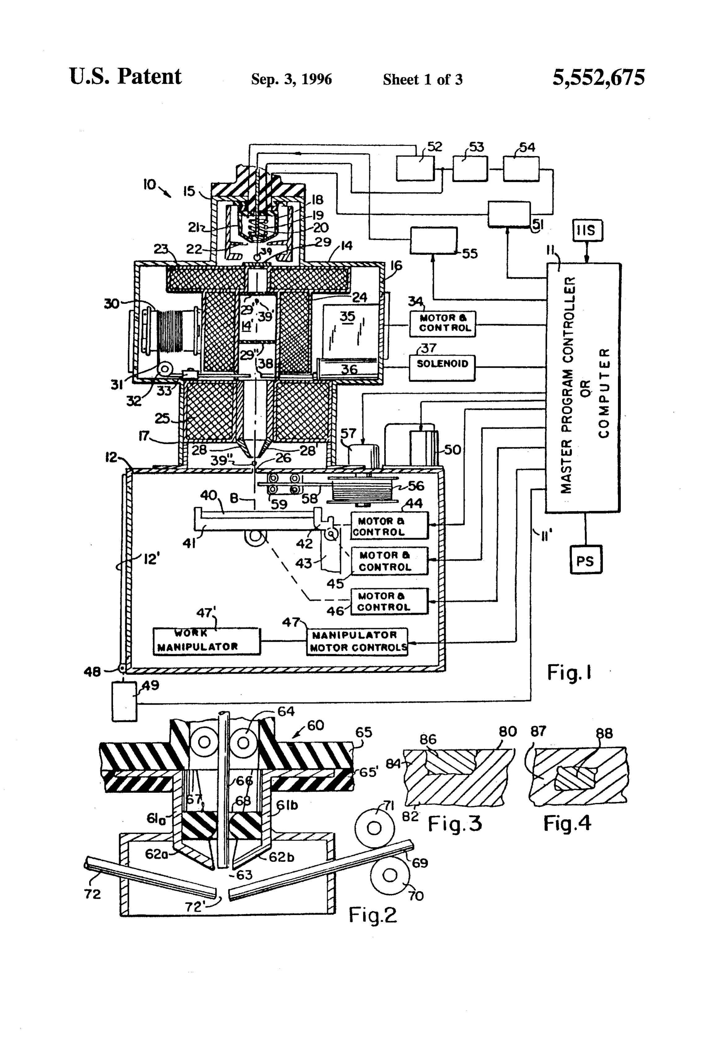
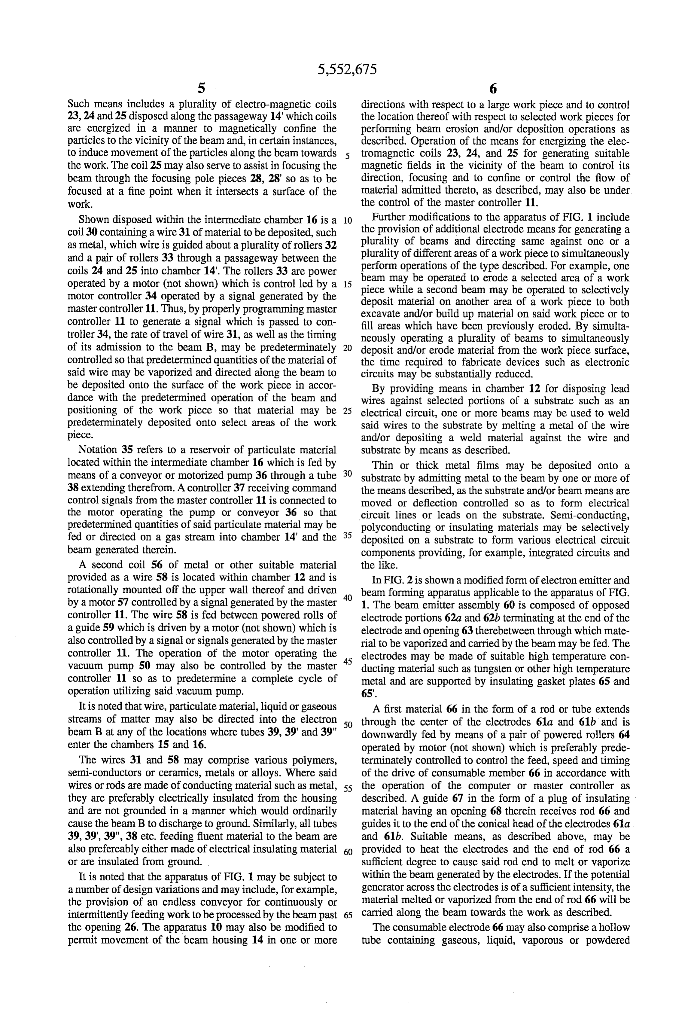
SUMMARY OF THE INVENTION pyrolizing waste material such as waste products of com This invention relates to an apparatus and method for bustion in furnaces and internal combustion engines reacting on matter by means of one or more forms of With the above and Such other objects in view as may radiation. In a preferred form, the radiation generates and hereinafter for fully appear, the invention consists of the transfers sufficient energy to the matter to cause a physical 25 novel constructions, combinations and arrangements of parts and/or chemical reaction such as by pyrolosis or electropy as will be more fully described and illustrated in the accom rolosis of select atoms of said matter to change its molecular panying drawings, but it is to be understood that changes, structure or to separate select atoms from molecules thereof variations and modifications may be resorted to which fall by breaking the bonds between such atoms and other atoms within the scope of the invention as claimed. of such molecules. In one form, the method is carried out 30 continuously with respect to matter such as comminuted BRIEF DESCRIPTION OF THE DRAWINGS metal containing ore, reaction of waste gas, water vapor per se or mixed with gas molecules or solid particles of a FIG. 1 is a side view with parts broken away for clarity catalyst, hydrocarbon molecule containing gas or mixtures of an electron beam apparatus for generating high tempera of gases and/or vapors containing molecules of matter to be 35 ture beam radiation for reacting on matter fed to or inter heated and reacted on. In said preferred form, reactions take sected by the radiation beam thereof; place at temperatures in the range of 1000 to 2000 degrees FIG. 2 is a side view of an electrode applicable to Centegrade; in one form in the range of about 1700 degrees apparatus of the invention;
centegrade to separate metal atoms from ore molecules FIG. 3 is a side view in cross section of one form of solid containing same in comminuted particles of such ore which 40 structure producible by an apparatus of the type shown in are continuously fed to a reaction zone in which is generated FIG. 1;
a plasma. Such process includes continuously forming such FIG. 4 is a side view of a modified form of structure of the refined metal to shape by spray depositing same onto a type shown in FIG. 3;
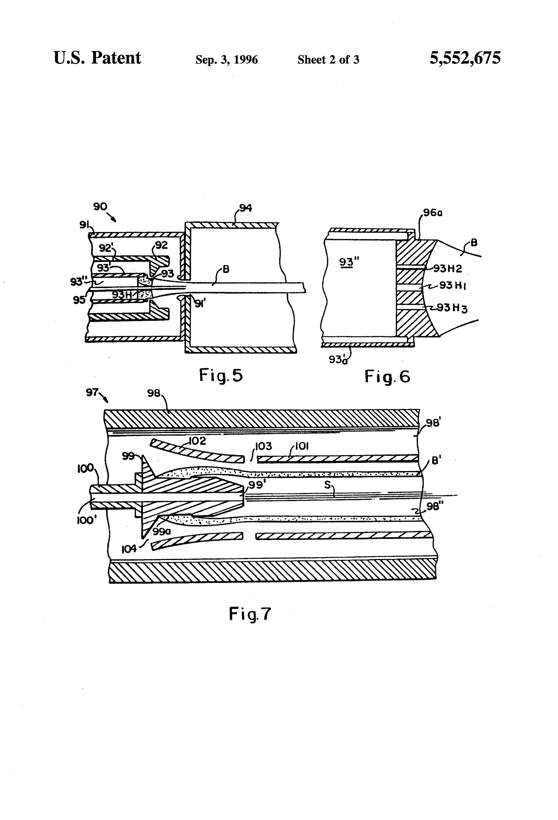
moving substrate or a shaping means such as a continuous FIG. 5 is a sectioned side view of a hollow beam casting die, mold or rolling mill. Other high temperature 45 generating apparatus applicable to the apparatus of FIG. 1; reactions include the continuous formation of carbon or synthetic diamond particles or coatings on a moving sub FIG. 6 is a sectioned side view of a modified form of the strate from carbon atoms stripped from molecules of a gas apparatus shown in FIG. 5;
or vapor containing same. Other forms of the invention FIG. 7 is a cross sectional view of anotherform of hollow include the high temperature disassociation of hydrogen 50 beam apparatus applicable to the apparatus of FIG. 1, from oxygen atoms and the incineration or pyrolizing of FIG. 8 is an end view with parts broken away for clarity products of combustion such as waste gases and solid of an elongated reaction chamber employing electrodes particles therein, vaporized waste liquids and the like. The which project into the chamber;
invention is also defined by improvements in apparatus and FIG. 9 is an end view with parts broken away and methods for generating high temperatures. 55 sectioned for clarity of an elongated reaction chamber
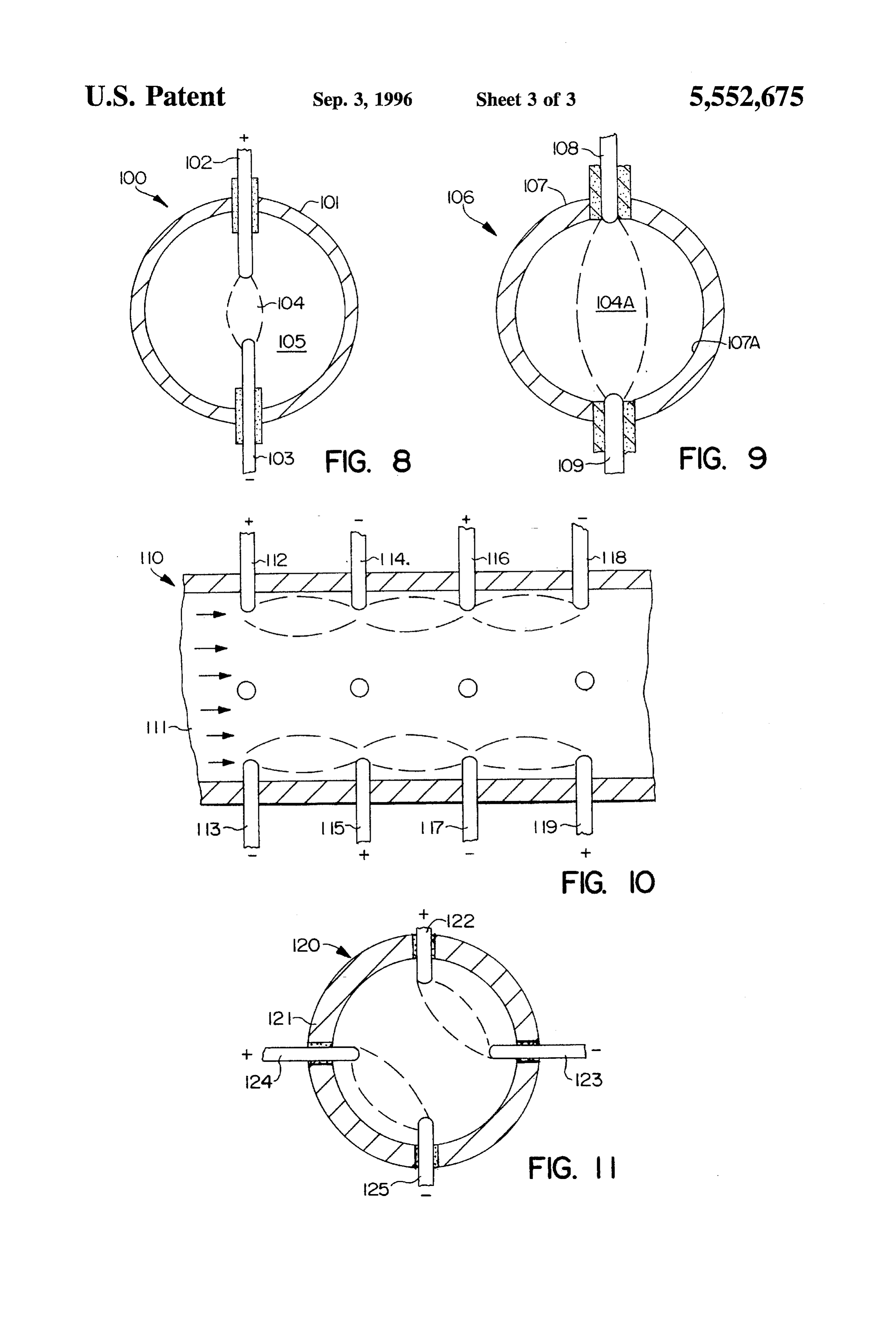
Accordingly it is a primary object of this invention to employing plasma generating electrodes which are space provide an apparatus and method for processing matter by separated the width of the chamber; w means of high temperature radiation. FIG. 10 is a side view in cross section of a modified Another object is to provide an apparatus and method for 60 elongated reaction chamber employing a plurality of elec reacting on matter with radiation generated in a plasma. trode pairs to generate a plasma or plurality of plasmas in the Another object is to provide an apparatus and method for chamber, reacting on matter with radiation generated by a plurality of FIG. 11 is an end view in cross section of a modified plasmas. elongated reaction chamber having adjacent electrodes for Another object is to provide an apparatus and method for 65 generating respective plasmas therebetween. reacting on matter with radiation generated by a plurality of Referring now to the drawings, FIG. 1 illustrates an different radiation generating means. electron beam apparatus 10 which may be operated to
Page 8
perform a plurality of different functions including the illustrated in FIG. 1 and is operatively connected to chamber selective deposition of one or more materials onto a sub 12 in the event that certain types of operations require that strate and/or the selective erosion or machining of said the work, during bombardment by the beam, be provided in substrate. The apparatus 10 is composed of a chamber 12 a WCL.
containing work to be processed by an electron beam B A master controller 11, such as an adjustable multi-circuit, which is generated within and directed through a cheer 14 self-recycling timer or other form of program controller or disposed on top of the chamber 12 communicating with said computer, is provided having a plurality of outputs 11' on chamber 12 by means of a small opening 26 in the upper which are generated respective wall of chamber 12. Disposed at the upper end of chamber controlling all of the describedcommand motors control signals for and other servos as 14 in a housing 15 is an electron beam generating assembly 10 well as those which will be described hereafter, so that the 18 which includes a filament 19 surrounding a rod-like cathode 20. The rod-shaped emitter 20 is indirectly heated apparatus 10 may be operated on a preprogrammed manner which includes the replacement of work previously pro by the filament 19 and generates an electron beam when a cessed suitable source of high voltage 55 is connected to the emitter table 41,with new work suitably aligned On the fixture or 19. Surrounding the described elements is a heat shield 21 15 ment of saidpredetermined the table 41 to location and subsequent move bring different areas thereof in and disposed directly beneath and adjacent the heat shield is alignment with the beam, the programmed operation of the a grid 22. Suitable filament supply, bombardment supply and beam and, as will be described hereafter, the programmed grid supply means denoted 52, 53 and 54 are provided and admission of one or more materials to the electron beam to connected to the respective elements of the emission assem permit their selective deposition onto selected areas of the bly 18 for generating a suitable electron beam which is surface of work piece 40 for the construction of electrical directed through a small opening in an anode plate 29, 20 circuits, thence into an elongated passageway 14' which is shown coating ofthearticles. selective contouring of plates, or the selective surrounded by electro-magnetic coils denoted 23, 24 and 25, the purpose of which will be described. Plates 29, 29' and 40Materials to be deposited onto the surface of the substrate may be admitted to the immediate vicinity of chamber 12 29" contain collimating slits for the beam B.
At the end of passageway 14 the beam passes a pair of 25 or at a plurality of points along the path of travel of the electron beam. Said material may be in the form of a solid focusing pole pieces 28 and 28' which serve to focus the rod or wire which is directed into the electron beam and beam through an opening 26 in the upper wall of chamber melted or vaporized thereby and carried along or within said 12 against a selected area of a work piece 40 disposed in beam to the area of the surface of the substrate intersected alignment with said opening.
30 by said beam so as to be deposited thereon or diffused into
The hereinabove described electron beam apparatus may the outer stratum of said substrate. The manner in which the be modified or supplemented with features found in known material is deposited or diffused will be a function of the electron gun apparatus such as provided, for example, in intensity of the beam which may be a constant potential or U.S. Pat. Nos. 2,944,172 and 3,009,050 and in the texts "The variable in accordance with command control signals gen Focusing of Charged Particles' edited by Albert Septier. 35 erated by the master controller 11. Accordingly, notation 55 The work piece 40 is shown as a flat substrate such as a refers to a source of high potential energy connected to the sheet or plate of metal or insulating material such as ceramic rod cathode. In certain instances, it may be desirable to or plastic and may comprise an electronic circuit board or provide an electronic or motor operated means within the other device on which it is desired to perform operations of unit 55 for varying the potential output thereof in accordance selectively adding material thereto and/or eroding or remov with a variable command control signal generated on the ing material therefrom. The substrate 40 is shown secured to input thereto by the master controller 11. Suitable means for a fixture or table 41 which is operative to move at least in varying the voltages applied to the filament and grid located two directions by predeterminately controlling respective in blocks 52 and 54 may also be provided which are varied motors 44 and 46 so as to locate any particular area of the in accordance with signals generated by the master control substrate 40 in direct alignment witch the opening 26 and the 45 ler 11. Accordingly, by such means, the potential and char beam passed therethrough to permit preprogrammed opera acteristics of the beam as it passes through the opening in tions of said beam on said substrate. A solenoid or motor 45, anode 29 in the chamber 14, may be predeterminately varied when controllably operated, actuates a clamp 42 which in accordance with the operation to be performed thereby. operates to secure the work piece 40 on the fixture 41 or Notations 39, 39' and 39" refer to respective conduits in release same so that it may be removed from said fixture. 50 the form of small diameter tubes extending into the cham The support 41 is movably mounted with respect to a base bers 15, 16 and 17 which respectively surround the beam 43 and is prefereably positionally controlled by respective emitter, the elongated passageway 14' and the focusing pole lead screws driven by the motors 44 and 46 in accordance pieces 28 and 28. Respective solenoid operated valves or with the manner of conventionally positioning a work table pumps controlled by signals generated by master controller with respect to a machine tool. Notation 47 refers to one or 55 11 may be utilized to admit predetermined quantities of more motors and controls therefore for operating an auto selected gases, vapors, liquids and/or powdered materials matic manipulator 47" located either within or exterior of the through the conduits 39, 39' and 39" to be ejected from the chamber 12 and operative to remove individual units of open ends thereof into the electron beam and to be carried work from the table 41 and to replace same with new work along the beam through the opening 26 against the surface to be processed in synchronization with the operation of the 60 of the work piece 40 intersected by the beam B. motor 45 operating the clamp 42. A door 12' is opened and The potential and movement of electrons or particles closed by means of a motor 49 operating a suitable cam within the beam B may be sufficient to carry particles or mechanism 48 at the door hinge to permits work to be droplets of material admitted to the beam along the beam to inserted into and removed from chamber 12.
the surface of the work piece. However, auxiliary means are
While the described electron beam generating means does 65 also provided in FIG. 1 to confine the material admitted to not ordinarily require vacuum to generate and direct the the beam to the vicinity of the beam and, in certain instances, electron beam against the work, a vacuum pump 50 is to induce its movement along the beam, toward the work.
Page 9
Such means includes a plurality of electro-magnetic coils directions with respect to a large work piece and to control 23, 24 and 25 disposed along the passageway 14" which coils the location thereof with respect to selected work pieces for are energized in a manner to magnetically confine the performing beam erosion and/or deposition operations as particles to the vicinity of the beam and, in certain instances, described. Operation of the means for energizing the elec to induce movement of the particles along the beam towards 5 tromagnetic coils 23, 24, and 25 for generating suitable the work. The coil 25 may also serve to assistin focusing the magnetic fields in the vicinity of the beam to control its beam through the focusing pole pieces 28, 28' so as to be direction, focusing and to confine or control the flow of focused at a fine point when it intersects a surface of the material admitted thereto, as described, may also be under work. the control of the master controller 11. Shown disposed within the intermediate chamber 16 is a 10 Further modifications to the apparatus of FIG. 1 include coil 30 containing a wire 31 of material to be deposited, such the provision of additional electrode means for generating a plurality of beams and directing same against one or a as metal, which wire is guided about a plurality of rollers 32 plurality of different areas of a workpiece to simultaneously and a pair of rollers 33 through a passageway between the perform operations coils 24 and 25 into chamber 14'. The rollers 33 are power beam may be operated of the type described. For example, one operated by a motor (not shown) which is control led by a 15 piece to erode a selected area of a work motor controller 34 operated by a signal generated by the while a second beam may be operated to selectively deposit material on another master controller 11. Thus, by properly programming master excavate and/or build up material area of a work piece to both controller 11 to generate a signal which is passed to con fill areas which have been previously on said work piece or to eroded. By simulta troller 34, the rate of travel of wire 31, as well as the timing neously operating a plurality of beams to simultaneously of its admission to the beam B, may be predeterminately 20 deposit and/or erode material from the work piece surface, controlled so that predetermined quantities of the material of the time required to fabricate devices such as electronic said wire may be vaporized and directed along the beam to circuits may be substantially reduced. be deposited onto the surface of the work piece in accor By providing means in chamber 12 for disposing lead dance with the predetermined operation of the beam and wires against selected portions of a substrate such as an positioning of the work piece so that material may be 25 electrical circuit, one or more beams may be used to weld predeterminately deposited onto select areas of the work said wires to the substrate by melting a metal of the wire piece. and/or depositing a weld material against the wire and Notation 35 refers to a reservoir of particulate material substrate by means as described.
located within the intermediate chamber 16 which is fed by Thin or thick metal films may be deposited onto a means of a conveyor or motorized pump 36 through a tube 30 substrate by admitting metal to the beam by one or more of 38 extending therefrom. A controller 37 receiving command the means described, as the substrate and/or beam means are control signals from the master controller 11 is connected to moved or deflection controlled so as to form electrical the motor operating the pump or conveyor 36 so that circuit lines or leads on the substrate. Semi-conducting, predetermined quantities of said particulate material may be polyconducting or insulating materials may be selectively fed or directed on a gas stream into chamber 14' and the 35 deposited on a substrate to form various electrical circuit beam generated therein. components providing, for example, integrated circuits and A second coil 56 of metal or other suitable material the like.
provided as a wire 58 is located within chamber 12 and is In FIG. 2 is shown a modified form of electron emitter and rotationally mounted off the upper wall thereof and driven 40 beam forming apparatus applicable to the apparatus of FIG. by a motor 57 controlled by a signal generated by the master 1. The beam emitter assembly 60 is composed of opposed controller 11. The wire 58 is fed between powered rolls of electrode portions 62a and 62b terminating at the end of the a guide 59 which is driven by a motor (not shown) which is electrode and opening 63 therebetween through which mate also controlled by a signal or signals generated by the master rial to be vaporized and carried by the beam may be fed. The controller 11. The operation of the motor operating the 45 electrodes may be made of suitable high temperature con vacuum pump 50 may also be controlled by the master ducting material such as tungsten or other high temperature controller 11 so as to predetermine a complete cycle of metal and are supported by insulating gasket plates 65 and operation utilizing said vacuum pump. 65.
It is noted that wire, particulate material, liquid or gaseous A first material 66 in the form of a rod or tube extends streams of matter may also be directed into the electron 50 through the center of the electrodes 61a and 61b and is beam B at any of the locations where tubes 39, 39' and 39" downwardly fed by means of a pair of powered rollers 64 enter the chambers 15 and 16. operated by motor (not shown) which is preferably prede The wires 31 and 58 may comprise various polymers, terminately controlled to control the feed, speed and timing semi-conductors or ceramics, metals or alloys. Where said of the drive of consumable member 66 in accordance with wires or rods are made of conducting material such as metal, 55 the operation of the computer or master controller as they are preferably electrically insulated from the housing described. A guide 67 in the form of a plug of insulating and are not grounded in a manner which would ordinarily material having an opening 68 therein receives rod 66 and cause the beam B to discharge to ground. Similarly, all tubes guides it to the end of the conical head of the electrodes 61a 39, 39', 39", 38 etc. feeding fluent material to the beam are and 61b. Suitable means, as described above, may be also prefereably either made of electrical insulating material 60 provided to heat the electrodes and the end of rod 66 a or are insulated from ground. sufficient degree to cause said rod end to melt or vaporize It is noted that the apparatus of FIG. 1 may be subject to within the beam generated by the electrodes. If the potential a number of design variations and may include, for example, generator across the electrodes is of a sufficient intensity, the the provision of an endless conveyor for continuously or material melted or vaporized from the end of rod 66 will be intermittently feeding work to be processed by the beam past 65 carried along the beam towards the work as described. the opening 26. The apparatus 10 may also be modified to The consumable electrode 66 may also comprise a hollow permit movement of the beam housing 14 in one or more tube containing gaseous, liquid, vaporous or powdered
Page 10
material fed to the open end thereof to be dispensed into the apparatus as described herein for performing various opera zone in which the beam is generated. tions on solids, liquids, gases or matter in the plasma state. Also illustrated in FIG. 2 is a rod 69 fed between powered "hollow or tubular electron beams' is meant electron beams rollers 70 and 71 to beneath the end of the conical electrodes which have the configuration of an elongated tube having a 61a and 61b so as to be admitted to the vicinity thereof in hollow interior or core which is not occupied by the radia which the intense beam is generated for melting or vapor tion beam.
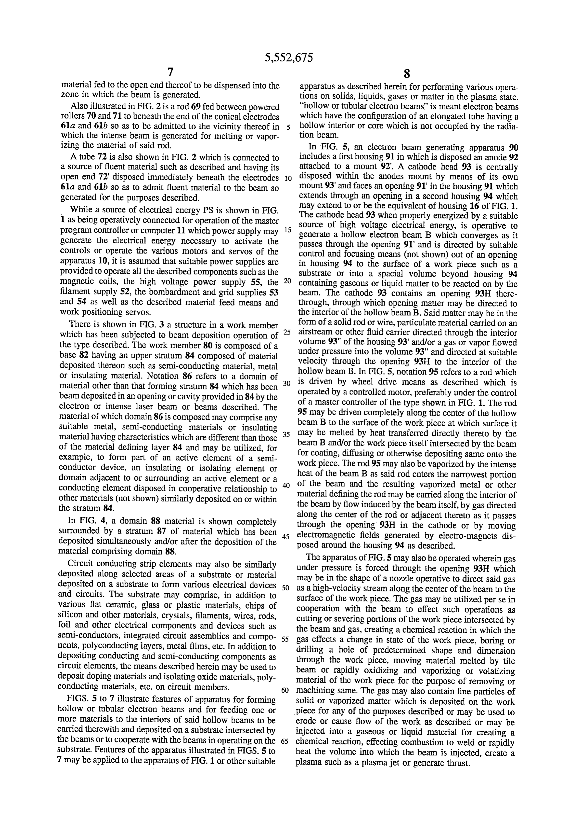
izing the material of said rod. In FIG. 5, an electron beam generating apparatus 90 A tube 72 is also shown in FIG. 2 which is connected to includes a first housing 91 in which is disposed an anode 92 a source of fluent material such as described and having its attached to a mount 92. A cathode head 93 is centrally open end 72' disposed immediately beneath the electrodes O disposed within the anodes mount by means of its own 61a and 61b so as to admit fluent material to the beam so mount 93' and faces an opening 91" in the housing 91 which generated for the purposes described. extends through an opening in a second housing 94 which While a source of electrical energy PS is shown in FIG. may cathode extend to or be the equivalent of housing 16 of FIG. 1. 1 as being operatively connected for operation of the master The source of head 93 when properly energized by a suitable high voltage electrical energy, is operative to program controller or computer 11 which power supply may 15 generate a hollow electron beam B which converges as it generate the electrical energy necessary to activate the passes through the opening 91' and is directed by suitable controls or operate the various motors and servos of the control and focusing means (not shown) out of an opening apparatus 10, it is assumed that suitable power supplies are in housing 94 to the surface of a work piece such as a provided to operate all the described components such as the substrate or into a spacial volume beyond housing 94 magnetic coils, the high voltage power supply 55, the 20 containing gaseous or liquid matter to be reacted on by the filament supply 52, the bombardment and grid supplies 53 beam. The cathode 93 contains an opening 93H there and 54 as well as the described material feed means and through, through which opening matter may be directed to work positioning servos. the interior of the hollow beam B. Said matter may be in the There is shown in FIG. 3 a structure in a work member form of a solid rod or wire, particulate material carried on an which has been subjected to beam deposition operation of 25 airstream or other fluid carrier directed through the interior the type described. The work member 80 is composed of a volume 93" of the housing 93' and/or a gas or vapor flowed base 82 having an upper stratum 84 composed of material under pressure into the volume 93" and directed at suitable deposited thereon such as semi-conducting material, metal velocity through the opening 93H to the interior of the or insulating material. Notation 86 refers to a domain of 30 hollow is driven beam B. In FIG. 5, notation 95 refers to a rod which by wheel drive means as described which is material other than that forming stratum 84 which has been operated by a controlled motor, preferably under the control beam deposited in an opening or cavity provided in 84 by the electron or intense laser beam or beams described. The of a master controller of the type shown in FIG. 1. The rod material of which domain 86 is composed may comprise any beam 95 may be driven completely along the center of the hollow suitable metal, semi-conducting materials or insulating 35 B to the surface of the work piece at which surface it material having characteristics which are different than those may be melted by heat transferred directly thereto by the of the material defining layer 84 and may be utilized, for beam B and/or the work piece itself intersected by the beam example, to form part of an active element of a semi for coating, diffusing or otherwise depositing same onto the conductor device, an insulating or isolating element or heat workpiece. The rod 95 may also be vaporized by the intense domain adjacent to or surrounding an active element or a of the beam B as said rod enters the narrowest portion conducting element disposed in cooperative relationship to of the beam and the resulting vaporized metal or other other materials (not shown) similarly deposited on or within material defining the rod may be carried along the interior of the beam by flow induced by the beam itself, by gas directed the stratum 84.
along the center of the rod or adjacent thereto as it passes
In FIG. 4, a domain 88 material is shown completely through the opening 93H in the cathode or by moving surrounded by a stratum 87 of material which has been electromagnetic fields generated by electro-magnets dis deposited simultaneously and/or after the deposition of the 45 posed around the housing 94 as described. material comprising domain 88. The apparatus of FIG.5 may also be operated wherein gas Circuit conducting strip elements may also be similarly under pressure is forced through the opening 93H which deposited along selected areas of a substrate or material may be in the shape of a nozzle operative to direct said gas deposited on a substrate to form various electrical devices 50 as a high-velocity stream along the center of the beam to the and circuits. The substrate may comprise, in addition to surface of the workpiece. The gas may be utilized perse in various flat ceramic, glass or plastic materials, chips of cooperation with the beam to effect such operations as silicon and other materials, crystals, filaments, wires, rods, cutting or severing portions of the work piece intersected by foil and other electrical components and devices such as semi-conductors, integrated circuit assemblies and compo 55 the gas beam and gas, creating a chemical reaction in which the effects a change in state of the work piece, boring or nents, polyconducting layers, metal films, etc. In addition to drilling a hole of predetermined shape and dimension depositing conducting and semi-conducting components as through the work piece, moving material melted by tile circuit elements, the means described herein may be used to beam or rapidly oxidizing and vaporizing or volatizing deposit doping materials and isolating oxide materials, poly material of the work piece for the purpose of removing or conducting materials, etc. on circuit members. 60 machining same. The gas may also contain fine particles of FIGS. 5 to 7 illustrate features of apparatus for forming solid or vaporized matter which is deposited on the work hollow or tubular electron beams and for feeding one or piece for any of the purposes described or may be used to more materials to the interiors of said hollow beams to be erode or cause flow of the work as described or may be carried therewith and deposited on a substrate intersected by injected into a gaseous or liquid material for creating a the beams or to cooperate with the beams in operating on the 65 chemical reaction, effecting combustion to weld or rapidly substrate. Features of the apparatus illustrated in FIGS. 5 to heat the volume into which the beam is injected, create a 7 may be applied to the apparatus of FIG. 1 or other suitable plasma such as a plasma jet or generate thrust.
Page 11
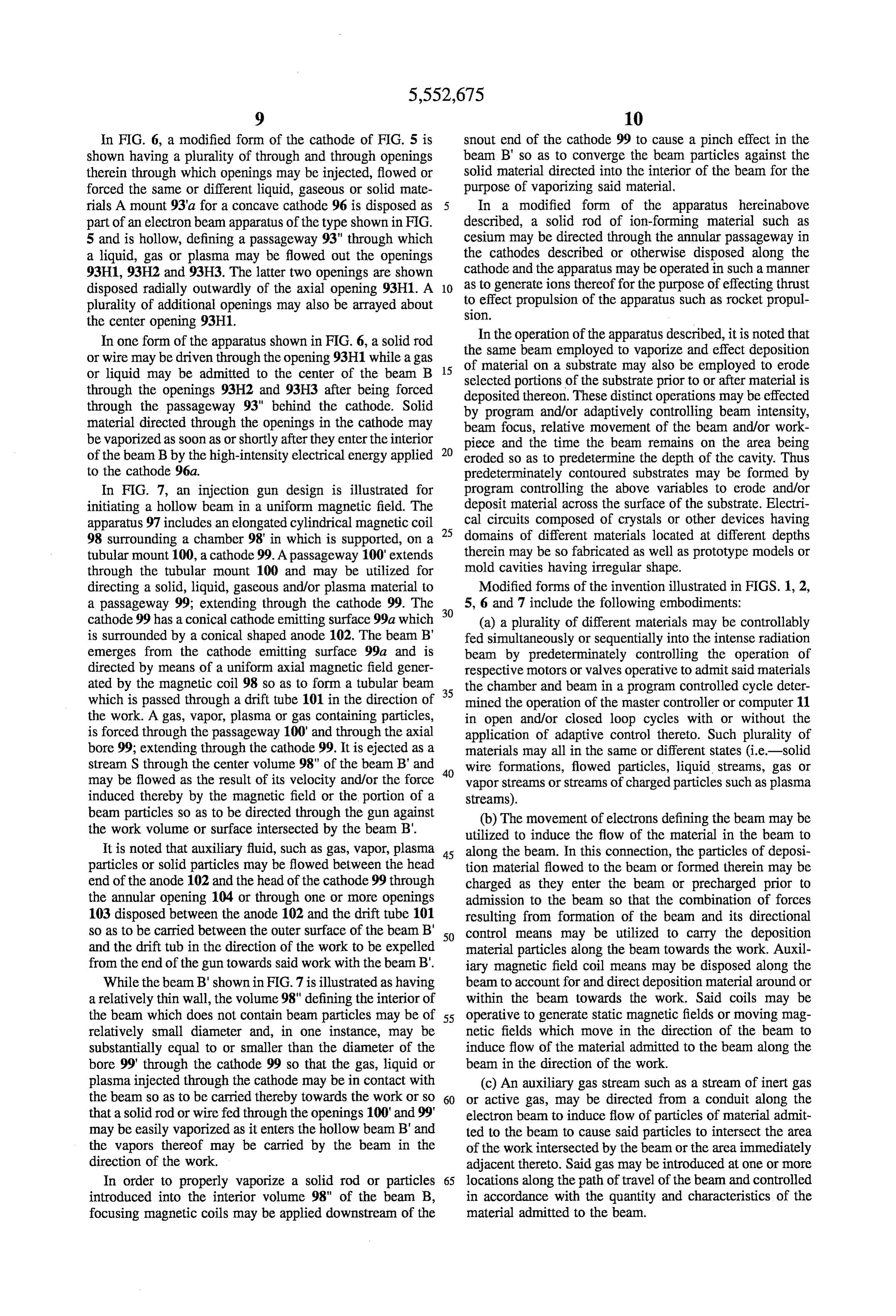
In FIG. 6, a modified form of the cathode of FIG. 5 is snout end of the cathode 99 to cause a pinch effect in the shown having a plurality of through and through openings beam B' so as to converge the beam particles against the therein through which openings may be injected, flowed or solid material directed into the interior of the beam for the forced the same or different liquid, gaseous or solid mate purpose of vaporizing said material. rials A mount 93'a for a concave cathode 96 is disposed as In a modified form of the apparatus hereinabove part of an electron beam apparatus of the type shown in FIG. described, a solid rod of ion-forming material such as 5 and is hollow, defining a passageway 93" through which cesium may be directed through the annular passageway in a liquid, gas or plasma may be flowed out the openings the cathodes described or otherwise disposed along the 93H1,93H2 and 93H3. The latter two openings are shown cathode and the apparatus may be operated in such a manner disposed radially outwardly of the axial opening 93H1. A 10 as to generate ions thereof for the purpose of effecting thrust plurality of additional openings may also be arrayed about to effect propulsion of the apparatus such as rocket propul
the center opening 93H1.
In one form of the apparatus shown in FIG. 6, a solid rod theInsame the operation of the apparatus described, it is noted that beam employed to vaporize and effect deposition or wire may be driven through the opening 93H1 while a gas of material on a substrate may also be employed to erode or liquid may be admitted to the center of the beam B 15 through the openings 93H2 and 93H3 after being forced selected portions of the substrate prior to or after material is through the passageway 93" behind the cathode. Solid deposited thereon. These distinct operations may be effected by program and/or adaptively controlling beam intensity, material directed through the openings in the cathode may beam focus, relative movement of the beam and/or work be vaporized as soon as or shortly after they enter the interior 20 piece and the time the beam remains on the area being of the beam B by the high-intensity electrical energy applied eroded so as to predetermine the depth of the cavity. Thus to the cathode 96.a. predeterminately contoured substrates may be formed by In FIG. 7, an injection gun design is illustrated for program controlling the above variables to erode and/or initiating a hollow beam in a uniform magnetic field. The deposit material across the surface of the substrate. Electri apparatus 97 includes an elongated cylindrical magnetic coil 25 cal circuits composed of crystals or other devices having 98 surrounding a chamber 98' in which is supported, on a domains of different materials located at different depths tubular mount 100, a cathode 99. A passageway 100' extends therein may be so fabricated as well as prototype models or through the tubular mount 100 and may be utilized for mold cavities having irregular shape. directing a solid, liquid, gaseous and/or plasma material to Modified forms of the invention illustrated in FIGS. 1, 2, a passageway 99; extending through the cathode 99. The 30 5, 6 and 7 include the following embodiments: cathode 99 has a conical cathode emitting surface 99a which (a) a plurality of different materials may be controllably is surrounded by a conical shaped anode 102. The beam B' fed simultaneously or sequentially into the intense radiation emerges from the cathode emitting surface 99a and is beam by predeterminately controlling the operation of directed by means of a uniform axial magnetic field gener respective motors or valves operative to admit said materials ated by the magnetic coil 98 so as to form a tubular beam 35 the chamber and beam in a program controlled cycle deter which is passed through a drift tube 101 in the direction of mined the operation of the master controller or computer 11 the work. A gas, vapor, plasma or gas containing particles, in open and/or closed loop cycles with or without the is forced through the passageway 100' and through the axial application of adaptive control thereto. Such plurality of bore 99; extending through the cathode 99. It is ejected as a materials may all in the same or different states (i.e.-solid stream S through the center volume 98" of the beam B' and 40 wire formations, flowed particles, liquid streams, gas or may be flowed as the result of its velocity and/or the force vapor streams or streams of charged particles such as plasma induced thereby by the magnetic field or the portion of a streams).
beam particles so as to be directed through the gun against (b) The movement of electrons defining the beam may be the work volume or surface intersected by the beam B'. utilized to induce the flow of the material in the beam to It is noted that auxiliary fluid, such as gas, vapor, plasma 45 along the beam. In this connection, the particles of deposi particles or solid particles may be flowed between the head tion material flowed to the beam or formed therein may be end of the anode 102 and the head of the cathode 99 through charged as they enter the beam or precharged prior to the annular opening 104 or through one or more openings admission to the beam so that the combination of forces 103 disposed between the anode 102 and the drift tube 101 resulting from formation of the beam and its directional so as to be carried between the outer surface of the beam B' 50 control means may be utilized to carry the deposition and the drift tub in the direction of the work to be expelled material particles along the beam towards the work. Auxil from the end of the gun towards said work with the beam B'. iary magnetic field coil means may be disposed along the While the beam B'shown in FIG. 7 is illustrated as having beam to account for and direct deposition material around or a relatively thin wall, the volume 98" defining the interior of within the beam towards the work. Said coils may be the beam which does not contain beam particles may be of 55 operative to generate static magnetic fields or moving mag relatively small diameter and, in one instance, may be netic fields which move in the direction of the beam to substantially equal to or smaller than the diameter of the induce flow of the material admitted to the beam along the bore 99 through the cathode 99 so that the gas, liquid or beam in the direction of the work.
plasma injected through the cathode may be in contact with (c) An auxiliary gas stream such as a stream of inert gas the beam so as to be carried thereby towards the work or so 60 or active gas, may be directed from a conduit along the that a solid rod or wire fed through the openings 100' and 99' electron beam to induce flow of particles of material admit may be easily vaporized as it enters the hollow beam B' and ted to the beam to cause said particles to intersect the area the vapors thereof may be carried by the beam in the of the work intersected by the beam or the area immediately direction of the work. adjacent thereto. Said gas may be introduced at one or more In order to properly vaporize a solid rod or particles 65 locations along the path of travel of the beam and controlled introduced into the interior volume 98" of the beam B, in accordance with the quantity and characteristics of the focusing magnetic coils may be applied downstream of the material admitted to the beam.
Page 12
(d) The flow of the hereinabove described materials along melting, vaporizing or otherwise affecting work or perform the beam may be effected by generating a plasma at least in ing a plurality of such operations. In this connection, a single part by the operation of the beam and/or auxiliary electrode laser may be employed to perform a plurality of operations means surrounding the electrode which operates to generate in cooperation with the electron gun, such as heating the the beam by admitting suitable material to the vicinity of cathode thereof and heating and vaporizing material to be said electrodes. Said plasma may be flowed as a stream deposited or implanted by the electron beam or a laser beam surrounding the beam by suitable magnetic field generating as described, heating their cathode and the work, generating means such as one or more electro-magnets disposed adja a plasma and heating the work, vaporizing material of the cent to the beam along its path of travel. Such plasma, if work during or before material is deposited by the electron generated at relatively high temperature, may also be opera 10 beam or laser beam or in the performance of they other tive to cooperate with the beam in heating the surface of the operations described. Gaseous, vaporous and/or particulate work. matter may also be controllably flowed through the plasma or plasmas so generated to perform select chemical and/or (e) The illustrated and above described embodiments may physical reactions thereon prior to deposition or separation all utilize one or more electron beams or one or more laser of the reaction products thereof. A single laser and/or light beams generated at sufficient intensity to effect the 15 electron beam may be split into a plurality of beams by desired described results. For example, solid wire or rod, suitable beam splitting means such as lenses, mirrors, or particulate, vaporous, liquid or gaseous material may be magnetic means. Such plural beams may be used to perform introduced into the intense light beam generated by the laser the same function such as heating, melting, cavitating, disposed in the vicinity of the electrodes illustrated and may vaporizing, implanting, etc. on different portions of the work be vaporized thereby and carried along the laser beam 20 or different functions on the same or different portions of the towards the work by one or more of the means described. work and to generate a plurality of plasmas at different select Particle charging or ionizing means may be provided in the locations.
vicinity of the laser or along the beam to form a plasma-like j) The described apparatus or variations thereof may flow of material along the beam towards the work. perform controlled operations on or with respect to liquids,
(f) A plurality of electron and/or laser beams may also be gases, vapors or plasmas into which beams and material(s) generated within the chamber and each predeterminately are directed within a chamber or within free space, to directed to intersect a selected area or the same area of the perform controlled chemical reactions, plasma generation, surface of the work. One or more materials to be deposited propulsion, burning and welding. Material or materials onto the work may be introduced into each beam. One of the 30 flowed or injected into, within or parallel to the laser or beams may be operative to erode preselected portions of the electron beam may be oxygen, an inert gas, a material to be work substrate while one or more other beams may be added for alloying, doping or adding to the material being operative to deposit selected amounts of material onto the heated or otherwise operated on by the beam. Substrate.
(k) Material directed into the beam in the vicinity of the (g) The described beam or begins may be operated at 35 work may comprise a combustible or explosive material sufficient intensity to not only vaporize or otherwise change operative to burn above the work or generate a controlled the state of material admitted to the beam but also to cause explosion for affecting the work such as generating a chemi the diffusion of said material into the substrate intersected by cal reaction therewith, eroding or pulverizing part or all of the beam after properly heating that portion of the substrate the work, generating a larger explosion in the vicinity of or receiving the fused material. In other words, the velocity of utilizing the work, generating a controlled nuclear reaction, the beam particles may be operative to cause deposition etc.
particles carried thereby to be diffused into the surface Modifications and improvements to the apparatus and stratum of the work intersected by the beam and deposition methods described are noted as follows: material.
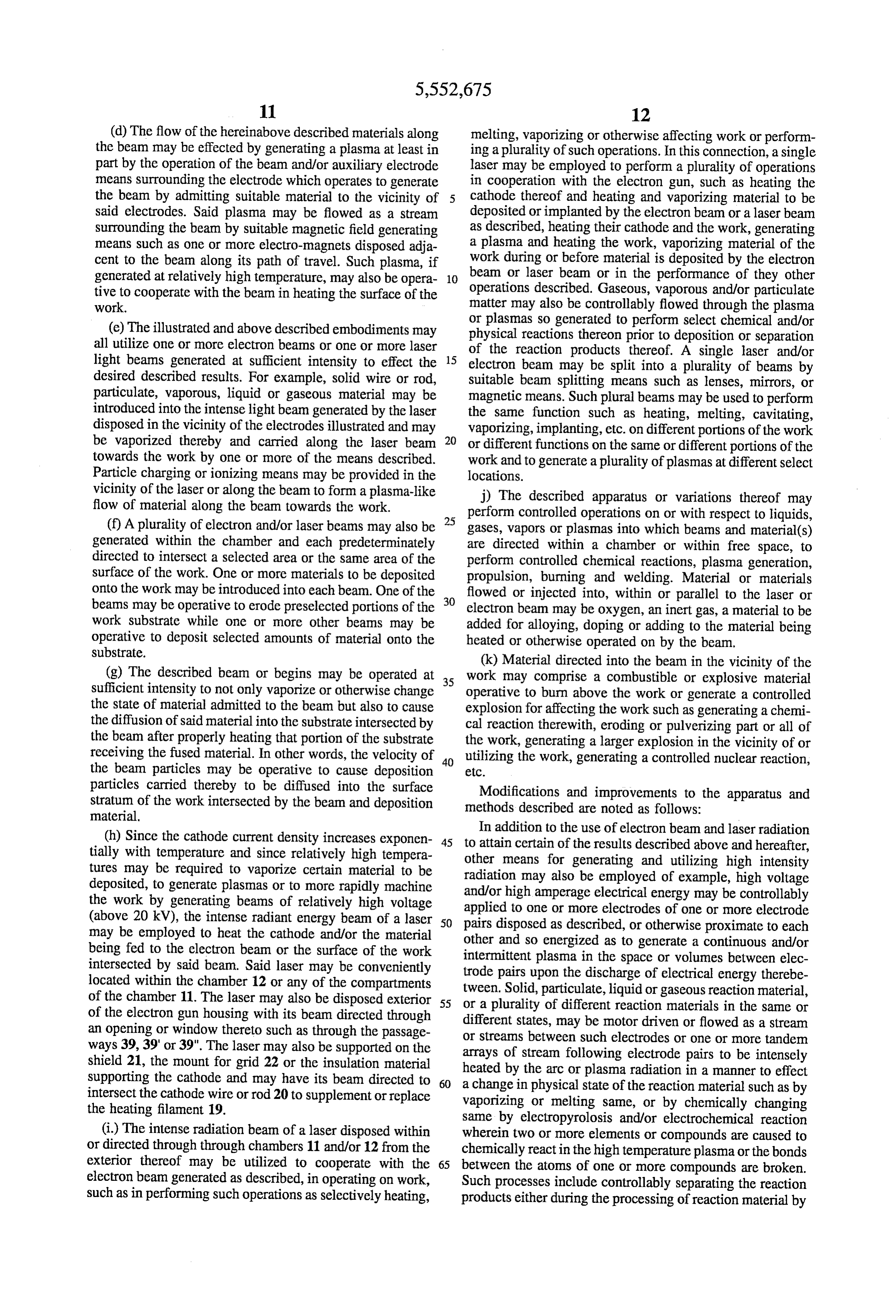
In addition to the use of electron beam and laser radiation (h) Since the cathode current density increases exponen 45 to attain certain of the results described above and hereafter, tially with temperature and since relatively high tempera other means for generating and utilizing high intensity tures may be required to vaporize certain material to be radiation may also be employed of example, high voltage deposited, to generate plasmas or to more rapidly machine the work by generating beams of relatively high voltage and/orapplied high amperage electrical energy may be controllably to one or more electrodes of one or more electrode (above 20 kV), the intense radiant energy beam of a laser 50 pairs disposed as described, or otherwise proximate to each may be employed to heat the cathode and/or the material other and so energized as to generate a continuous and/or being fed to the electron beam or the surface of the work intermittent plasma in the space or volumes between elec intersected by said beam. Said laser may be conveniently trode pairs upon the discharge of electrical energy therebe located within the chamber 12 or any of the compartments tween. Solid, particulate, liquid or gaseous reaction material, of the chamber 11. The laser may also be disposed exterior 55 or a plurality of different reaction materials in the same or of the electron gun housing with its beam directed through different states, may be motor driven or flowed as a stream an opening or window thereto such as through the passage or streams between such electrodes or one or more tandem ways 39, 39' or 39". The laser may also be supported on the arrays of stream following electrode pairs to be intensely shield 21, the mount for grid 22 or the insulation material supporting the cathode and may have its beam directed to 60 a changebyinthe heated arc or plasma radiation in a manner to effect physical state of the reaction material such as by intersect the cathode wire or rod 20 to supplement or replace vaporizing or melting same, or by chemically changing the heating filament 19. same by electropyrolosis and/or electrochemical reaction (i.) The intense radiation beam of a laser disposed within wherein two or more elements or compounds are caused to or directed through through chambers 11 and/or 12 from the chemically react in the high temperature plasma or the bonds exterior thereof may be utilized to cooperate with the 65 between the atoms of one or more compounds are broken. electron beam generated as described, in operating on work, Such processes include controllably separating the reaction such as in performing such operations as selectively heating, products either during the processing of reaction material by
Page 13
one or more of the high temperature plasmas, so generated may also be staggered along the duct and energized to as matter is flowed therethrough or immediately after pass generate respective arcs for progressively and/of completely ing from such single or multiple plasmas. Such separation heating all or select fluid particles or molecules passed may be effected by known separation means such as by through the duct to temperatures sufficient to effect tile gravity, centrifuging, vortex flow, filtering, radiation beam described chemical and/or physical reactions. While the or a combination of such means in continuous processing, electrodes 102 and 103 of FIG. 8 are operable to generate an one or more of the products of a plasma reaction may be arc near the center of the duct, other electrode pairs down flowed or conveyed to the next stage of processing to partake stream and/or upstream thereof may be space separated one in one or more further chemical physical reactions down or more distances closer to the wall of the duct on either or stream of the plasma generating apparatus. 10 both sides of the axis of the aligned electrodes illustrated, In a particular form, of the invention, a gas, liquid, or either close to the electrodes illustrated and/or for some particles of a solid or two or more solids perse or disposed distance downstream upstream thereof. If the duct is made in a fluid stream may be flowed by gravity or pumped of an electrically conducting material such as metal, the through a duct containing a plurality of electrode pairs electrodes are preferably insulatedly supported thereon as disposed at select spaced intervals along such duct, across 15 shown by suitable insulating collars or deposited material. each of which electrode pairs is generated one or more Depending on the voltage and the gaseous matter in the duct, plasmas, such as a continuous or intermittent arc or series of the plasma arc, may be generated in the gap 104 and/or in intermittent and/of continuous arcs, through which plasma a volume extending laterally therefrom.
Such reaction fluid is passed to effect heating of the mol Longitudinally extending guides or vanes secured to or ecules thereof to either break the bonds between one or more 20 forming part of the wall 101 may be so shaped and disposed of the compounds of the fluid or/its particles or to effect a as to guide and cause working fluid passing longitudinally select chemical reaction or reactions with respect to ele through the duct through the one or more plasmas generated ments and/or compounds of the fluid passing through the therein as described.
duct. The duct, elongated reaction chamber may be made of Variations in the construction and operation of the appa or lined with a suitable high temperature or chemical cor 25 ratus 100 of FIG. 8 are noted as follows: rosion resistent material, such as Pyroceram or the like. In a particular form, all or a portion of such duct or reaction A. Electrode pairs of the type shown and/or modifications chamber may be rotated about its longitudinal axis or thereof may be supported by adjacent or opposite portions of otherwise, to effect one or more results. If the duct is the Wall of the elongated reaction chamber or duct at a irregularly shaped and/or contains one or more vanes 30 electrodes number of location longitudinally along the duct. Such therein, a helical swirling movement may be imparted to the may be located and positioned with respect to working fluid or products of reaction passing through the each other and the flow volume 105 of the duct that duct to centrifuge or otherwise separate atoms or molecules substantially all of the gas molecules and/or solid particles which are products of the high temperature reaction which passing through the duct pass through one or more plasmas generated within the duct and are heated to a suitable high takes place within the duct. If the electrode-pairs are located 35 temperature off center within the duct, the plasmas generated thereby will to effect a desired physical and/or chemical be rotated through the working fluid as it passes longitudi reaction to effect reactions of the types described herein nally through the duct to optimize the reaction results if the involving, for example, the pyrolizing and reduction of flow of such working fluid is controlled to effect such waste gases and particles therein, to reducing of ores to optimized reaction. In a particular form, such plasmas may 40 remove a metal or metals therefrom, the removal or ele be generated by locating the electrodes of the electrode pairs ments, such as carbon, from gases and solid particulate at or near opposite walls of the duct to permit the plasma materials and the formation of synthetic diamond or other generating arcs to span the width of the duct, thus permitting materials therefrom, the separation of hydrogen from oxy the plasmas to react on all fluid passing therebetween and gen in water vapor, the reduction of carbon monoxide from filling the interior volume of the duct. The line or plane 45 combustion carbon and gas to form carbon dioxide and/or elemental oxygen thereof, breaking the bonds between between pairs of such electrodes may be radially angulated with respect to the other pairs of electrodes so as to react on carbon and oxygen atoms of carbon dioxide to form carbon and oxygen thereof perse or in the present of a gaseous or all or more of the fluid material passing though the elongated particulate catalyst.
reaction chamber or duct.
In FIG. 8 is shown a radiation reaction apparatus 100 50 disposed B. The apparatus 100 may comprise, form part of or be defined by an elongated cylindrical tube or duct 101 formed longitudinally within a smokestack connected to a of a suitable metal, metal alloy,ceramic such as a ceremet or furnace or an exhaust pipe for an internal combustion high temperature glass or a combination of such materials engine.
preferably with one covering or coating the other, such as a C. Microwave, laser or other form of beamed energy may metal tube interiorally coated with a high temperature 55 be generated outside the reaction chamber 101 and directed ceramic. Insulatedly supported by opposite wall portions of through one or more openings in the side wall thereof to scan the duct 101 are respective electrodes 102 and 103 of an and heat the fluid contents of the chamber per se or in electrode pair which protrude into the interior volume 105 of combination with the heat generated by the electrically the duct and terminate apart to define a gap or space 104 discharged electrode pair or pairs of electrodes disposed therebetween. Molecules of gas, vapor or solid or liquid 60 within the volume 105 at one or more locations therein as particulate material or combinations thereof to be reacted on, described.
are pumped, fed by gravity or otherwise flowed through duct D. Replacement of worn electrodes may be effected by an 101 or on a stream of neutral gas molecules such as nitrogen, automatic handling means, such as an automatic manipula past and between the electrodes while suitable electrical tor service one or more reaction chambers. Alternatively, energy is applied across the electrodes to generate a high 65 either or both electrodes may be power driven at a fixed rate temperature arc or plasma therebetween. A single electrode or in accordance with signals generated by a sensing means pair or a plurality of electrode pairs aligned with each other sensing electrode wear or the distance between electrodes,
Page 14
by a motor or motors controlled by a microprocessor or respect to the molecules of the liquid and/or particles of solid computer. Each electrode or a bank or banks of longitudi matter thereon. In addition to various chemical reactions, nally aligned or staggered electrodes may be secured to a hydrogen atoms may be so separated from oxygen atoms of common bus which is driven by a motor supported by the water generating bubbles of hydrogen and oxygen gas wall 101 of the duct, in a manner to maintain a constant or mixture in the water passed through the reaction chamber or predetermined gap between all electrode pairs. duct which bubbles may be collect-downstream by know E. A single plasma may be generated between a plurality means, Such mixtures may be stored or burned or otherwise of electrode pairs longitudinally aligned or staggered longi used in further reactions or may have the hydrogen and tudinally along the duct or separate and discrete plasmas oxygen components thereof separated from each other for may be so generated which are of the same intensity or 10 various separate uses. In a particular form, all or substan predetermined intensities depending on the manner in which tially all of the liquid passed into one end of the reaction duct may be reduced to its atomic components or otherwise heating or pyrolizing material in the duct is effected. For example, a plurality of plasmas may be generated along the caused to undergo a complete chemical reaction. duct operable to gradually or step increase the temperature In FIG. 9 a high temperature reaction apparatus 106 of particles or gas molecules flowing through the duct from 5 includes an elongated duct or tube 107 of the type described plasma to plasma. Plasmas may be generated completely having one or more pairs of electrodes 108 and 109 sup across the diameter of the volume 105 and/or longitudinally ported by opposite portions of the wall or walls of the duct. therein by means such as illustrated in FIGS. 9, 10 and 11 or The inner ends 108A and 109A of the electrodes 108 and 109 modifications thereof. terminate at or near the inside surface of the tube-or duct 107 which may be constructed as described. Thus the arc A is
F. The radially extending electrodes 102 and 102 may be 20 generated supplemented or replaced with electrodes or electrode across the center as shown and extends substantially completely assemblies which extend longitudinally though and within of the interior volume 110 of the duct 107. the duct 101. Electrodes may also be formed of electrically The construction of the duct and electrode mounting may be conducting material or materials such as carbon, metal, in accordance with the teachings of FIG. 8. A plurality of metal alloys, superconducting material or combinations pair of such electrodes may be supported aligned along the thereof which partially coat or line the inside surface of the duct, staggered or helically disposed therealong to heat and duct 101. The duct may also be fabricated of a plurality of effect reactions with respect to a select amount or substan longitudinally extending wall sections of conducting elec tially all the particles or molecules of fluid material passed through the duct. The arcs may be generated as a single trode material which are insulated from each other by plasma or plurality of separated plasmas continuously and/or respective wall section made of insulating material such as intermittently.
In the latter mode of operation, all arcs may high temperature ceramic or glass material. Thus adjacent or be generated simultaneously or in a select or predetermined opposite sections of the duct wall made of conducting sequence along the duct to optimize the reaction or reactions material such as graphite or carbon metal, metal alloy or taking place within the duct. Feedback signals generated by superconducting material or a combination thereof may be one or more sensors sensing such reaction variables as oppositely charged to provide plasma arcing therebetween 35 current voltages, amperages, plasma temperatures and for the purposes described. shape, reaction products, etc. may be employed in a closed G. A single computer supported exterior of the duct 101, loop process control system to control such variables as flow may be employed to control all process variables including rate, composition, voltage and amperage. Products of reac the feeding and flow of one or more reaction fluids to one tion such as atoms and molecules of gas, vapor and/or solid end of the duct, current applied continuously or intermit 40 material(s) may be collected downstream of the reaction tently to the electrodes to generate continuous or intermittent Zone or zones and separated or used as described. plasmas therebetween, electrode replenishment, etc. While FIG. 10 may represent a side view of the apparatus Further modifications to the apparatus and methods of FIG.9 when multiple pairs of electrodes are employed, if described are noted as follows: 45 adjacent electrodes on the same side of the wall are of Where atoms of products of the described high tempera opposite polarity, plasma arcs may be generated therebe ture heating of gas or particulate matter are separated from tween as shown rather than across the center of the duct as the molecules thereof, they may be continuously combined in FIG. 9. A combination of arcs generated close to the wall, with other atoms or molecules of additional matter continu as in FIG. 10 and across the duct as in FIG.9 may also be ously fed to the reaction chamber, Zone or zones or may be 50 employed in yet another embodiment of the invention. absorbed by solid particles of matter, so delivered. For In FIG. 11 is shown a modified form of the invention suitably dissipating waste particles and gas molecules of illustrated in FIGS. 8 to 10 the features of which may be combustion, particles of one or more low cost materials such combined with features of the other figures or employed per as calcium carbonate, calcium chloride, or other material se. The reactor 120, as in the construction of the other may be fed to the reaction chamber or zone separate from or 55 reactors, may comprise an elongated cylindrical duct or mixed with the waste gas and particles to react on or absorb chamber or a spherical or otherwise shaped chamber through the components of reaction resulting from the described high which reaction fluid is continuously force flowed by pump, temperature heating. Such additional particulate material blower, gravity or a combination thereof. Supported by the may be employed to absorb and/or react with the products of side wall of the chamber 121 and protruding into the volume the high temperature reaction to reduce same to disposable interior thereof are a plurality of electrodes. Four electrodes solid waste or provide one or more new and useful products 122, 123, 124 and 125 are shown defining two pairs of thereof.
electrodes disposed near opposite sides of the chamber.
Liquids or liquids containing solid particulate material Electrodes 122 and 123 which are located laterally adjacent and/or solid chemicals dissolved therein may be flowed each other define one electrode pair across or between which through reaction apparatus of the types illustrated in FIGS. 65 a first plasma P1 is genera generated when suitable electrical 8 to 11 whereby arc generated between the electrode pairs potential is applied to the positive electrode 122 and breaks thereof heat and effect reactions of the types described with down or discharges in the gap at the end thereof to the end
Page 15
of the negative electrode 123. The other electrode pair is through the duct to react on fluid particles or molecules composed of electrodes 124 and 125 between which a therein to effect the results described, perse or in combi second plasma is generated when the positive electrode is nation with each other and/or one or more plasma arcs energized with suitable electrical energy. It is noted that generated as described. Reactions which may be effected additional pairs of electrodes of the type provided in FIG. 11 include (a) high temperature reactions on a gas or gases, may be located laterally between those shown and/or lon vapor or vapors and/or particles of the same or different gitudinally down the duct at respective locations to provide materials passed longitudinally through the duct to form new either a unitary plasma, a plurality of plasmas between two compositions; (b) high temperature or plasma reaction on or more adjacent electrode pairs or a plurality of discrete gas or vapor molecules to separate select atoms therefrom spaced apart plasmas as require to effect desired reaction 10 such as atoms of carbon from methane gas which may be results. deposited onto a moving substrate within or beyond the end Energy required to generate plasma arcs across the elec of the duct to form synthetic diamond coating on such trode pairs described may be derived from suitable sources substrate or may form particles of synthetic diamond within of hydroelectric or otherwise generated electrical energy. and/or beyond the open end of the duct; (c) high temperature Arrays of solar-to-electrical energy generating cells or reaction on particles of ore in a manner to separate metal focused solar energy to electrical energy generating means 15 and/or other atoms and the deposition thereof onto a moving may also be employed to generate the required electrical substrate located within or beyond the end of the duct or energy for energizing the electrodes after such energy is reaction chamber; (d) high temperature reaction on mol boosted or increase to a proper voltage and amperage by ecules and/or particles of waste products such as the par suitable electrical equipment. ticles and gases of combustion in a furnace or reaction 20 chamber such as an incinerator; (e) high temperature reac
In a particular form of the apparatus and method tion with respect to carbon monoxide and/or carbon dioxide described immediately above, a chemical composition or ore formed in a combustion or incineration process to separate containing one or more elements, such as metal to be separated from the composition or ore, may be comminuted carbon atoms from oxygen atoms thereof and to deposit the by known means or otherwise provided in flowable paticu 25 movinglyatoms carbon per se or as diamond particles or film on a substrate beyond the open end of the duct; (f) high late form and flowed perse to and through one or more high temperature reactions on process or combustion products temperature plasmas generated between one or more elec where non-combustion matter such as particles of solid trode pairs by the application of suitable electrical energy therebetween and the high temperature of the plasma applied liquid reactants or absorbant material are introduced into the to heat the composition or ore to a temperature sufficient to 30 one or one duct at or more locations thereof to partake in or absorb more of the products of reaction.
break the bonds between atoms of metal or other element of the molecules of the composition or ore whereby such metal If the ducts of FIGS. 8 to 11 are of large diameter, such or other element becomes separated from the remaining as in the configurations of smokestacks of an industrial elements of the compound or ore. Such separated materials process or furnace, beamed radiation may be generated as may be collected in respective reservoirs or flow streams 35 described and directed in one or more fixed paths longitu thereof by gravity, centrifuging or other known separating dinally to intersect, heat and react on particles and/of mol means and separately stored for use or used in a continuous ecules of the fluid reaction material passing therethrough. process. Metal so separated may be in a molten state or One or more laser or electron beams may also be generated further heated to become molten and alloyed, atomized or and directed against a nuclear fuel, such as separately fed fed directly to a forming means such as a mold, continuous 40 particles of trittium-deuterium passed into one or more casting die or substrate where it may be solidified to a select select locations of the duct or stack, to thermonuclearly shape or shapes. The method may define a continuous ignite same and generated intermittent thermonuclear reac process for separating metal or metals directly from ore and tions for heating reaction material passing longitudinally shaping same in one or more stages. From a continuous through the duct or stack and incinerating or reacting on casting die or mold, for example, the metal so refined and 45 same as described herein.
formed may be continuously fed to a rolling means such as Modified forms of the invention involving apparatus and a rolling mill for reducing and shaping same to plate, sheet, methods as described above may involve the high tempera wire, rod or tubing. If atomized as described immediately ture separation of carbon atoms from oxygen atoms of gas after separation from the compound or ore, the metal may be molecules of combustion waste gases produced in the opera sprayed against a shaping surface such as the surface of a 50 tion of furnaces, internal combustion engines and chemical mold, rolls of a rolling mill, elongated driven member such reactors. Such carbon and oxygen atoms may be separated as a continuously formed or coil fed sheet, strip, rod, tube or and collected in separate containers as useful byproducts or other shape and solidified as a layer or coating thereon as the used downstream of the described high temperature reaction substrate is driven past the atomizing means. Zone or zones in a continuing process or processes. In modified forms of the embodiments of FIGS. 8 to 11, 55 Where the described process is employed to separate suitable vanes or the like may be attached to the inside metal from its ore by breaking the bonds between atoms of surface of the tubes or ducts illustrated to impart a helical or metal and atoms of other elements in the ore, continuous swirling movement to the fluid passed through the ducts to known means may be operated to comminute ore or chemi assure that substantially all the molecules or particles thereof cals into particles of same of small enough size to permit the pass through a plasma or arc or arcs generated along the 60 continuous feeding and high temperature processing Of duct. Furthermore, the tube or duct may also be rotated to same into desired molten or particulate metal which maybe pass the plasma arcs generated therein through most or a separated by known means from the other products of the select quantity of the reaction fluid as it is flowed longitu high temperature reaction.
dinally through the duct. Beam radiation generated by an electron gun or laser as It is also noted that one or more beams of the one or more 65 described herein may also be employed per se or in com described radiations (laser, electron beam, microwave, etc. bination with one or more electrically discharged electrode radiation) may be passed longitudinally and/or laterally pairs to generate or enhance one or more plasmas or plasma
Page 16
arcs for effecting high temperature chemical and/or physical reaction material may flow by gravity away from the moving reactions with respect to gaseous, vaporous and/or particu member Atoms or particles so formed or separated by high late material or a combination of materials which are flu temperature radiation may be employed to coat the moving idically mixed and fed as a stream to the reaction zone or substrate as a permanent coating or removed therefrom zones defined by such plasma or plasmas or are fed on downstream of the coating location and collected. separate streams thereof to such Zone or Zones. A single What is claimed is:
radiation beam or a plurality of such beams may be mag 1. Apparatus for effecting high temperature reactions netically or optically split into a plurality of beams which are comprising:
directed along separate paths and are employed to either a) a reaction chamber, generate or enhance a plasma generated between electrodes 10 b) inlet means to said chamber for admitting reaction or by other means. Fluidic gaseous or particulate solid or material to the interior of said chamber, liquid matter may be stream directed through such plasma or aligned series of plasmas to heat the molecules thereof to c) a source of electrical energy connected to said chamber high temperatures at which they react or the atoms thereof and electrode means supported within said chamber for separate when the molecular bonds are broken or shattered 15 receiving and converting electrical energy from said by the high temperature. For example, various ores contain source to a high temperature electrical plasma, ing metal or metals, when subjected to temperatures in the d) control means for controlling the application of elec range of 1700 degrees centegrade will have their metal trical energy from said source to said electrode means, atoms separated from the molecules containing same and e) an outlet from said chamber through which products of such metal may be collected by gravity, centrifugal separa reaction may be passed, tion, filtration, magnetic means or a combination thereof, in 20 f) a supply of fluent reaction material, a continuous formation and separation process. A single g) power operated means for effecting and controlling the radiation beam, such as a laser or electron beam generated flow of said fluent reaction material to said chamber, as described may be passed between a plurality of electrode h) control means for said power operated means, and pairs properly aligned to permit matter to be reacted on to 25 pass therethrough and be reacted on by the radiation of the i) master control means connected to said control means plasma and the radiation beam applied thereto to effect for controlling the application of electrical energy to controlled chemical and physical reactions as described. The said electrode means and said control means for said pressure or force of the radiation beam may be employed to power operated means to effect the automatic control of separate select particles of reaction material, molecules or a reaction with respect to reaction material controllably atoms thereof, from other gaseous or particulate matter by 30 fed to said chamber by the high temperature of said force flowing same along a path or paths to effect such plasma generated at said electrode means. separation. Select atoms of the reaction material may react electrode 2. An apparatus in accordance with claim 1 wherein said to a select wavelength or wavelengths or frequently of the means comprises a pair of electrodes supported radiation beamed to the reaction zone or zones while other 35 within said chamber.
atoms or molecules of matter resulting from the high tem 3. An apparatus in accordance with claim 1 wherein said perature reaction may be subjected to radiation force suffi electrode supported means comprises a plurality of pairs of electrodes within said chamber.
ciently different therefrom to effect radiation separation of the products of the reaction by generating and separately 4. An apparatus in accordance with claim 3 including separate control means for controlling the application of directing the flows of different molecules and/or atoms of 40 electrical matter to different locations within and/or exterior of the energy to each of said plurality of pairs of elec reaction zone or chamber with laser beams of different wave trodes, each of said separate control means being separately lengths. controllable by said master control means to effect the Beamed radiation, such as microwave radiation, may also generation and control of plasmas between each of said plurality be employed per se or in combination with laser and/or 45 5. An apparatus of pairs of electrodes. electron gun generated beam radiation, one or more elec in accordance with claim 1 wherein said trode pair generated plasmas or the like, to effect the supply of reaction material comprises a supply of particles of matter.
chemical and/or physical reaction or reactions described. 6. An apparatus in accordance with claim 1 wherein said For example, such microwave radiation may be generated supply of reaction material includes a supply of molecules of and focused as a beam to a reaction zone defined by one or 50 matter in a freely flowable state. more pairs of electrode between which is discharged high 7. An apparatus in accordance with claim 1 including a voltage and/or high amperage electrical energy as a con tinuous or intermittent discharge to generate a continuous or power operated meansoffor plurality of supplies different reaction materials, separate effecting the flows of each of said intermittent plasma. Such microwave radiation may also be different reaction materials from each of said supplies, directed and focused through a plurality of plasmas gener 55 control means for each of said ated as described by a plurality of electrically discharged means, said master control meansseparate being power operated programmed to electrode pairs disposed close to each other or in a line along selectively control each of said control means to effect the the path of flow of working fluid or fluids selective control of each of said separate power operated The arrangements and methods described above may also means to control the admissions of said different materials to be employed to selectively deposit a material or materials on 60 said reaction chamber.
to stationary or moving substrate for coating, implanting 8. An apparatus in accordance with claim 1 wherein said and/or separating same from matter such as ore particles, master control means comprises a computer. chemical compositions or the like as described. Particles or 9. An apparatus in accordance with claim 1 including atoms which are not so deposited onto such a moving means for guiding fluent reaction material admitted to said substrate, which may comprise a wire, rod, tube, sheet or 65 chamber along a path within said chamber which intersects strip which is continuously formed and driven, supplied and passes through a plasma generated adjacent said elec from a coil or other source or otherwise conveyed past the trode means.
Page 17
10. An apparatus in accordance with claim 1 wherein said flow said reaction material through said chamber and to electrode means comprises at least one pair of electrodes cause the flow of product of reaction through said outlet disposed with their discharge surfaces near opposite wall means from said chamber.
portions of said chamber to effect, when energized, the 18. An apparatus in accordance with claim 16 including generation of a plasma substantially completely across said means within said reaction chamber for generating a plu
rality of plasmas at different locations within said chamber 11. An apparatus in accordance with claim 1 wherein said to permit the radiant energy of said plurality of plasmas to reaction chamber is an elongated duct. react on the reaction material admitted to said chamber. 12. An apparatus in accordance with claim 1 wherein said 19. An apparatus in accordance with claim 16 wherein at supply of reaction material comprises a supply of fluent 10 least a portion of said reaction chamber is an elongated duct, matter containing hydrocarbon molecules and wherein the means supported within said elongated duct portion of said electrical energy applied to said electrode means is of an reaction chamber for receiving electrical energy and con intensity to generate a plasma adjacent said electrode means verting said electrical energy to a plurality of plasmas at of sufficient intensity to strip the carbon atoms from said hydrocarbon molecules. 15 select locations along the length of said duct portion wherein 13. An apparatus in accordance with claim 1 further reaction material passed through said reaction chamber and including means for supporting an article within said reac along the elongated duct portion thereof will be heated by tion chamber during the operation of said apparatus, said the radiant energy of each of said plasmas generated at said control being operable to control the application of electrical select locations along the length of said elongated duct. energy to said electrode means in a manner to generate a 20 20. A high temperature reaction apparatus comprising in plasma capable of causing at least one product or reaction to combination:
deposit as a layer on the surface of an article supported a) a reaction chamber, within said chamber.
14. An apparatus in accordance with claim 1 including b) means for controllably admitting a solid material to means for conveying products of reaction beyond said outlet 25 c) meansreaction said chamber, for generating high temperature radiation as a means from said reaction chamber.
15. An apparatus in accordance with claim 14 wherein beam and directing said radiation beam through said said master control means is operable to control the opera chamber, tion of said conveying means. d) means for locating said solid material in said reaction 16. An apparatus for effecting high temperature reactions 30 chamber whereby radiation generated by said beam comprising: will intersect heat and react on said solid material to a) a reaction chamber, cause a select amount of said solid material to vaporize, b) inlet means to said chamber for admitting reaction e) means for removing the vapor of said solid material from said chamber, material to the interior of said chamber, 35 21. A high temperature reaction apparatus comprising: c) a source of electrical energy, a) a reaction chamber, d) means supported within said chamber for receiving b) means for controllably admitting and predeterminedly electrical energy from said source and converting said disposing a workpiece made of solid material at a select electrical energy to a high temperature plasma within
location in said reaction chamber, e) control means for controlling the application of elec c) means for generating a high temperature plasma at a trical energy from said source to said high temperature select location within said chamber, plasma converting means, d) means for directing radiant energy from said plasma at f) a supply of reaction material, said workpiece and causing said radiant energy to react g) power operated means for controllably admitting said 45 on and effect a predetermined change in said solid reaction material to said chamber, material of said workpiece wherein at least a portion of said solid material of said workpiece is heated and h) control means for said power operated means, and vaporized, and wherein at least a portion of said solid i) master control means operable to control said control material of said workpiece is separated from said means for controlling the application of said electrical 50 workpiece without vaporization, so that both vaporous energy to said high temperature plasma converting and solid materials from said workpiece exist in said means and for also controlling said control means for reaction chamber, and said power operated means to control the admission of e) means for controllably removing said vaporous and reaction material to said chamber and to effect a con solid materials from said workpiece and from said trolled high temperature reaction on reaction by the 55 chamber and separating said vaporous and solid mate plasma generated within said chamber, and material rials from each other.
within said chamber, and 22. An apparatus in accordance with claim 21, further j) outlet means through which products of reaction within comprising means for supporting and controllably position said chamber may flow from said chamber. ing said workpiece in at least one select position within said 17. An apparatus in accordance with claim 16 wherein 60 reaction chamber during the application of said high tem said reaction material is admitted to said chamber in a fluent perature plasma radiation to said workpiece. state and said power operated means for admitting said reaction material to said chamber is operable to continuously k k k
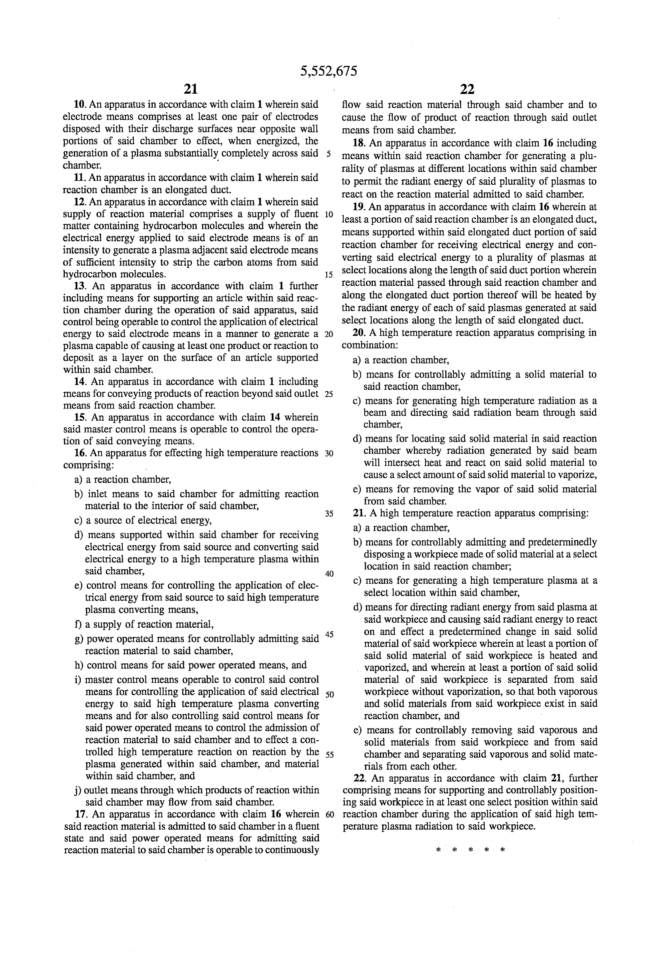
Page 18
UNITED STATES PATENT AND TRADEMARK OFFICE
CERTIFICATE OF CORRECTION
PATENT NO. : 5,552,675 Page 1 of 1
APPLICATIONNO. : 07/849297
INVENTOR(S) : Jerome H. Lemelson
It is certified that error appears in the above-identified patent and that said Letters Patent is hereby corrected as shown below:
On the title page, item Notice should read -- This Patent is subject to a Terminal Disclaimer --
Signed and Sealed this
Third Day of October, 2006
WDJ
JON. W. DUDAS
Director of the United States Patent and Trademark Office
Provenance
- Collection
- Cited prior art
- Original PDF
- patentimages.storage.googleapis.com →
- Filed
- 1992-03-10
- Pages
- 18
- Method
- pdftotext (the PDF's own text layer) + pdftoppm 300dpi page scans
- Source
- Google Patents bibliographic record
- Granted
- 1996-09-03
- Inventors
- Jerome H. Lemelson; LEMELSON MEDICAL EDUCATION and RESEARCH FOUNDATION LP
- Transcribed from
- patentimages.storage.googleapis.com →