patent · US5548952
Hydrogen jet-phase engine
27 August 1996
Page 1 — bibliographic record
IIIHIIIHIIII
United States Patent (19) 11 Patent Number: 5,548,952 Stock et al. 45) Date of Patent: Aug. 27, 1996
54 HYDROGEN JET-PHASE ENGINE 2,916,877 12/1959 Walter .................................... 60/39.55 3,984, 193 10/1976 Yu ........................................ 41.5128.
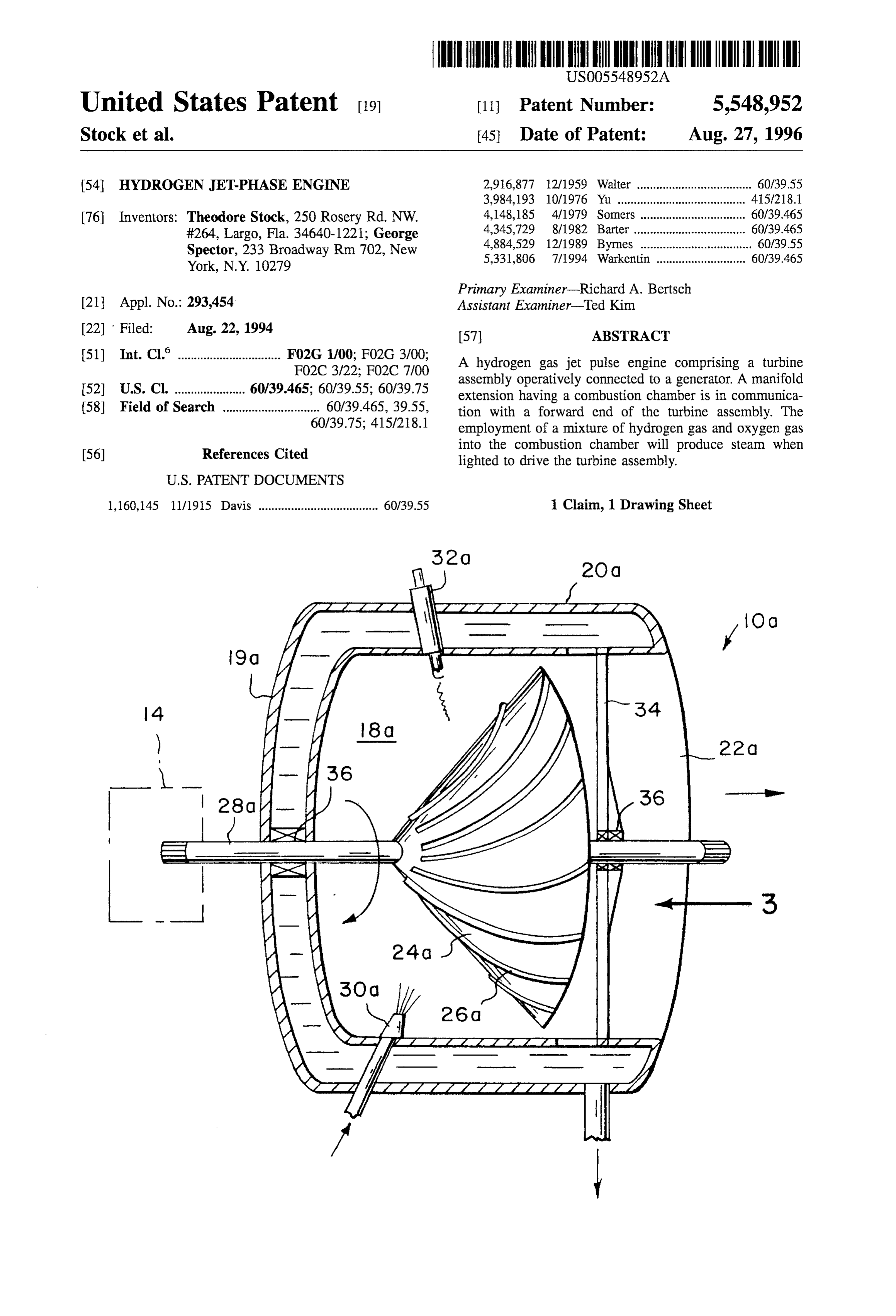
76 Inventors: Theodore Stock, 250 Rosery Rd. NW. 4,148,185 4/1979 Somers ................................. 60/39.465 #264, Largo, Fla. 34.640-1221; George 2.5 5. 3. Ele a was a - - - - a a a- - - - - - - - - (E. Spector, 233 Broadway Rm 702, New ww ly yrnes ............................ York, N.Y. 10279 5,331,806 7/1994 Warkentin ............................ 60/39.465 Primary Examiner-Richard A. Bertsch 21 Appl. No.: 293.454 Assistant Examiner-Ted Kim 22 Filed: Aug. 22, 1994 57) ABSTRACT (51) Int. Cl. ................................ F02G 1/00; F02G 3/00; A hydrogen gas jet pulse engine comprising a turbine FO2C 3/22; FO2C 7700 assembly operatively connected to a generator. A manifold 52 U.S. Cl. ..................... 60/39.465; 60/39.55; 60/39.75 extension having a combustion chamber is in communica 58 Field of Search .............................. 639,465, 39.55, tion with a forward end of the turbine assembly. The 60/39.75; 41.5/218.1 employment of a mixture of hydrogen gas and oxygen gas into the combustion chamber will produce steam when 56) References Cited lighted to drive the turbine assembly.
1,160,145 11/1915 Davis ..................................... 60/39.55 1 Claim, 1 Drawing Sheet
Page 2
Drawing sheet — no readable text.
Page 3
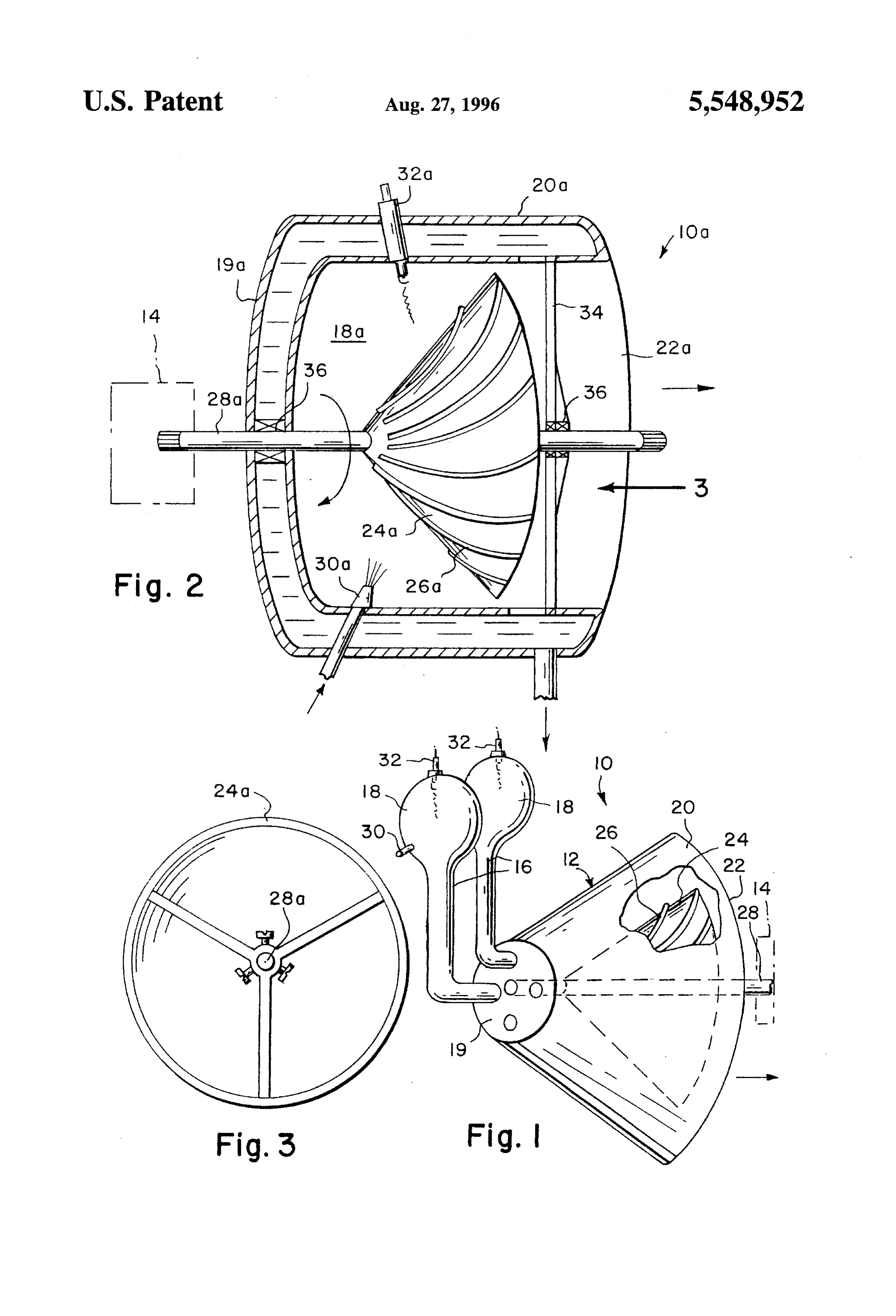
HYDROGEN JET-PHASE ENGINE The turbine assembly 12 includes a cone-shaped station ary housing 20 having an exhaust port 22 at a rearward end.
BACKGROUND OF THE INVENTION A cone-shaped turbine wheel 24 has a plurality of curved vanes 26 radially mounted thereon. A power take off shaft 28
The instant invention relates generally to hydrogen gas is affixed to the turbine wheel 24 and is rotatively connected driven turbines and more specifically it relates to a hydrogen to the housing 20. The generator 14 is connected to one end gas jet pulse engine, which provides a safe usage of hydro of the shaft 28 extending from the housing 20. gen gas with oxygen gas as the combustion fuel. The manifold extension 16 contains an inlet tube 30 for There are available various conventional hydrogen gas O carrying the mixture of hydrogen gas and oxygen gas into driven turbines which do not provide the novel improve the combustion chamber 18. A spark plug 32 is for igniting ments of the invention herein disclosed. the mixture of hydrogen gas and oxygen gas in the com bustion chamber 18.
SUMMARY OF THE INVENTION FIG. 2 shows a modified hydrogen gas jet pulse engine
A primary object of the present invention is to provide a 10a comprising a stationary water cooled housing 20a hydrogen gas jet pulse engine that will overcome the short having a combustion chamber 18a at a forward end 19a and comings of the prior art devices. an exhaust port 22a at arearward end. A cone-shaped turbine Another object is to provide a hydrogen gas jet pulse wheel 24a has a plurality of curved vanes 26a radially 20 mounted thereon. A power take off shaft 28a is affixed to the engine that uses in a safe way the combination of hydrogen gas with oxygen gas as the combustion fuel for the engine, turbine wheel 24a (see FIG. 3) and is rotatively connected instead of burning of petroleum fuels. to the housing 20a via a brace 34 and bearings 36. A An additional object is to provide a hydrogen gas jet pulse generator 14 is connected to one end of the shaft 28a engine in which the exhaustable by product will be steam 25 extending into the from the housing 20a. A fuel nozzle 30a extends housing 20a at the combustion chamber 18a for that will turn into water, thereby being better for the envi spraying a mixture of hydrogen gas and oxygen gas into the ronment and will not pollute the atmosphere.
A further object is to provide a hydrogen gas jet pulse combustion chamber 18a. An igniter 32a extends into the housing 20a at the combustion chamber 18a opposite from engine that is simple and easy to use. 30 the fuel nozzle 30a, for igniting the mixture of hydrogen gas A still further object is to provide a hydrogen gas jet pulse and oxygen gas in the combustion chamber 18a, thereby engine that is economical in cost to manufacture. producing steam to rotate the turbine wheel 24a and the shaft Further objects of the invention will appear as the descrip 28a to operate the generator 14.
tion proceeds. 35
To the accomplishment of the above and related objects, OPERATION OF THE INVENTION this invention may be embodied in the form illustrated in the As shown in FIG. 1, a mixture of hydrogen gas and accompanying drawings, attention being called to the fact, oxygen gas is carried by the inlet tube 30 into the combus however, that the drawings are illustrative only, and that tion chamber 18. The spark plug 32 will ignite the mixture changes may be made in the specific construction illustrated 40 to produce steam to drive the turbine assembly 12 and open and described within the scope of the appended claims. the generator 14.
BRIEF DESCRIPTION OF THE DRAWING As shown in FIG. 2, a mixture of hydrogen gas and FIGURES oxygen gas is sprayed into the combustion chamber 18a by 45 the fuel nozzle 30a. The igniter 32a will ignite the mixture
FIG. 1 is a perspective view with parts broken out of a first to produce steam to rotate the turbine wheel 24a and the embodiment of the instant invention. shaft 28a to operate the generator 14. FIG. 2 is a cross sectional view of a second embodiment While certain novel features of this invention have been of the instant invention. 50 shown and described and are pointed out in the annexed FIG. 3 is an end view of the turbine wheel perse taken in claims, it will be understood that various omissions, substi the direction of arrow 3 in FIG. 2. tutions and changes in the forms and details of the device illustrated and in its operation can be made by those skilled
DETAILED DESCRIPTION OF THE in the art without departing from the spirit of the invention. 55 What is claimed is:
PREFERRED EMBODIMENTS
1. A hydrogen gas jet pulse engine comprising:
Turning now descriptively to the drawings, in which a) a stationary water cooled housing with inlet and outlet similar reference characters denote similar elements having a combustion chamber within a forward end and throughout the several views, FIG. 1 illustrates a hydrogen an exhaust port within a rearward end within said gas jet pulse engine 10 comprising a turbine assembly 12 housing, operatively connected to a generator 14. A manifold exten b) a cone-shaped turbine wheel between said ends having sion 16 has a combustion chamber 18 in communication a central longitudinal axis with a plurality of curved with a forward end 19 of the turbine assembly 12. The vanes radially mounted thereon within said forward employment of a mixture of hydrogen gas and oxygen gas 65 end;
into the combustion chamber 18 will produce steam when c) said wheel having a peripheral edge spaced from said lighted to drive the turbine assembly 12. housing, a power take off shaft affixed to said turbine
Page 4
wheel along said axis and rotatively mounted on said the mixture of hydrogen gas and oxygen gas in the housing, including a generator connected to one end of combustion chamber, thereby producing steam to rotate said shaft extending from said housing; said turbine wheel and said shaft to operate the gen d) a fuel nozzle extending into said housing at the erator and whereby products of combustion escape combustion chamber for spraying a mixture of hydro gen gas and oxygen gas into the combustion chamber from said combustion chamber through the space about and said peripheral edge to said exhaust port. e) an igniter extending into said housing at the combus tion chamber opposite from said fuel nozzle for igniting ck k k k k

Provenance
- Collection
- Cited prior art
- Original PDF
- patentimages.storage.googleapis.com →
- Filed
- 1994-08-22
- Pages
- 4
- Method
- pdftotext (the PDF's own text layer) + pdftoppm 300dpi page scans
- Source
- Google Patents bibliographic record
- Granted
- 1996-08-27
- Inventors
- Theodore Stock; George Spector
- Transcribed from
- patentimages.storage.googleapis.com →