patent · US4235693
Submersible energy storage apparatus
25 November 1980
Page 1 — bibliographic record
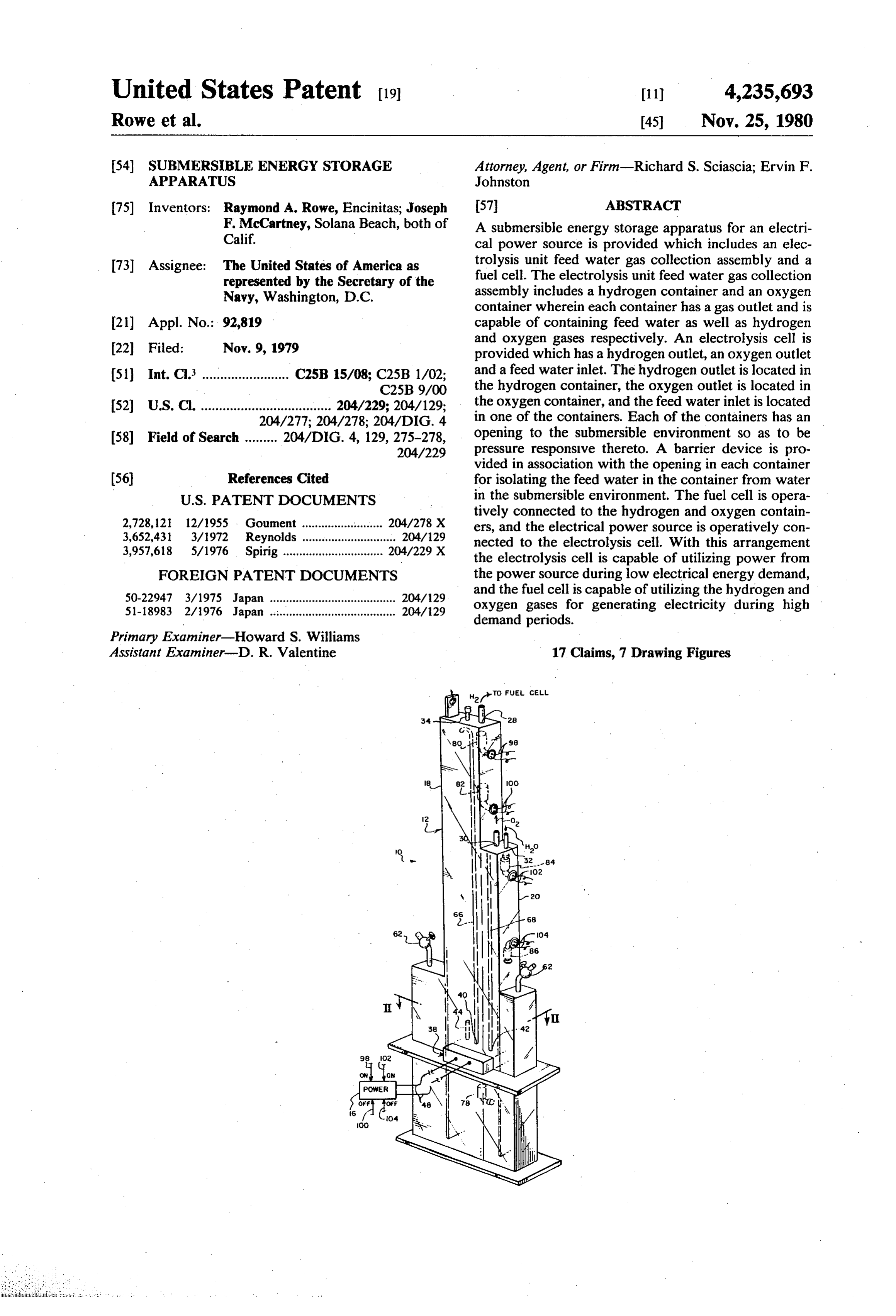
United States Patent 19 11 4,235,693 Rowe et al. 45 Nov. 25, 1980 (54) SUBMERSIBLE ENERGY STORAGE Attorney, Agent, or Firm-Richard S. Sciascia; Ervin F. APPARATUS Johnston 75) Inventors: Raymond A. Rowe, Encinitas; Joseph 57 ABSTRACT F. McCartney, Solana Beach, both of A submersible energy storage apparatus for an electri Calif. cal power source is provided which includes an elec 73) Assignee: The United States of America as trolysis unit feed water gas collection assembly and a represented by the Secretary of the fuel cell. The electrolysis unit feed water gas collection Navy, Washington, D.C. assembly includes a hydrogen container and an oxygen container wherein each container has a gas outlet and is 21) Appl. No.: 92,819 capable of containing feed water as well as hydrogen and oxygen gases respectively. An electrolysis cell is 22 Filed: Nov. 9, 1979 provided which has a hydrogen outlet, an oxygen outlet (51) Int. C. ........................ C25B 15/08; C25B 1/02; and a feed water inlet. The hydrogen outlet is located in C25B 9/00 the hydrogen container, the oxygen outlet is located in 52 U.S.C. .................................... 204/229; 204/129; the oxygen container, and the feed water inlet is located 204/277; 204/278; 204/DIG. 4 in one of the containers. Each of the containers has an 58 Field of Search ......... 204/DIG. 4, 129, 275-278, opening to the submersible environment so as to be 204/229 pressure responsive thereto. A barrier device is pro vided in association with the opening in each container 56 References Cited for isolating the feed water in the container from water
tively connected to the hydrogen and oxygen contain 2,728, 12 12/1955 . Goument ..... ... 204/278 X ers, and the electrical power source is operatively con 3,652,431 3/1972 Reynolds ............................. 2O4/129 nected to the electrolysis cell. With this arrangement 3,957,618 5/1976 Spirig ............................... 204/229 X the electrolysis cell is capable of utilizing power from FOREIGN PATENT DOCUMENTS the power source during low electrical energy demand, 50-22947 3/1975 Japan ....................................... 204/129 and the fuel cell is capable of utilizing the hydrogen and 51-18983 2/1976 Japan ... ... 204/29 oxygen gases for generating electricity during high demand periods.
Primary Examiner-Howard S. Williams
Assistant Examinter-D. R. Valentine 17 Claims, 7 Drawing Figures
Page 2
Drawing sheet — no readable text.
Page 3
Drawing sheet — no readable text.
Page 4
Drawing sheet — no readable text.
Page 5
electrolysis cell. With this arrangement power can be
SUBMERSIBLE ENERGY STORAGE, APPARATUS stored from utility plants during low demand periods to meet the power needs during high demand periods.
STATEMENT OF GOVERNMENT INTEREST Also, the invention will store power from intermittent The invention described herein may be manufactured 5 low power generators to supply power on a continuous and used by or for the Government of the United States basis to user equipment.
of America for governmental purposes without the OBJECTS OF THE INVENTION payment of any royalties thereon or therefor. An object of the present invention is to provide an BACKGROUND OF THE INVENTION . . . O energy Storage apparatus.
Most oceanographic equipment operates in two Another object is to provide an energy storage appa modes, namely: a power requirement mode and a no ratus which is operable in a water submerged environ power requirement mode. Examples of such oceano ment, graphic equipment are transmitters, processors, light 15 Another object is to provide an ocean submersible beacons, and some oceanographic instruments. Some energy storage apparatus which is capable of storing equipment is left for prolonged periods in remote loca smaller amounts of energy for meeting a larger energy tions. In these instances the power source must be on demand at a subsequent time.
site. A typical power source is batteries. However, Yet another object is to provide an electrolysis unit batteries require periodic replacement or charging. In feed water gas collection assembly for a submersible order to leave the oceanographic equipment unattended 20 energy Storage apparatus.
for long periods of time attempts have been made to These and other objects of the invention will become provide energy from natural sources, such as solar cells more readily apparent from the ensuing specification or wave action, however, the energy available from when taken together with the drawings.
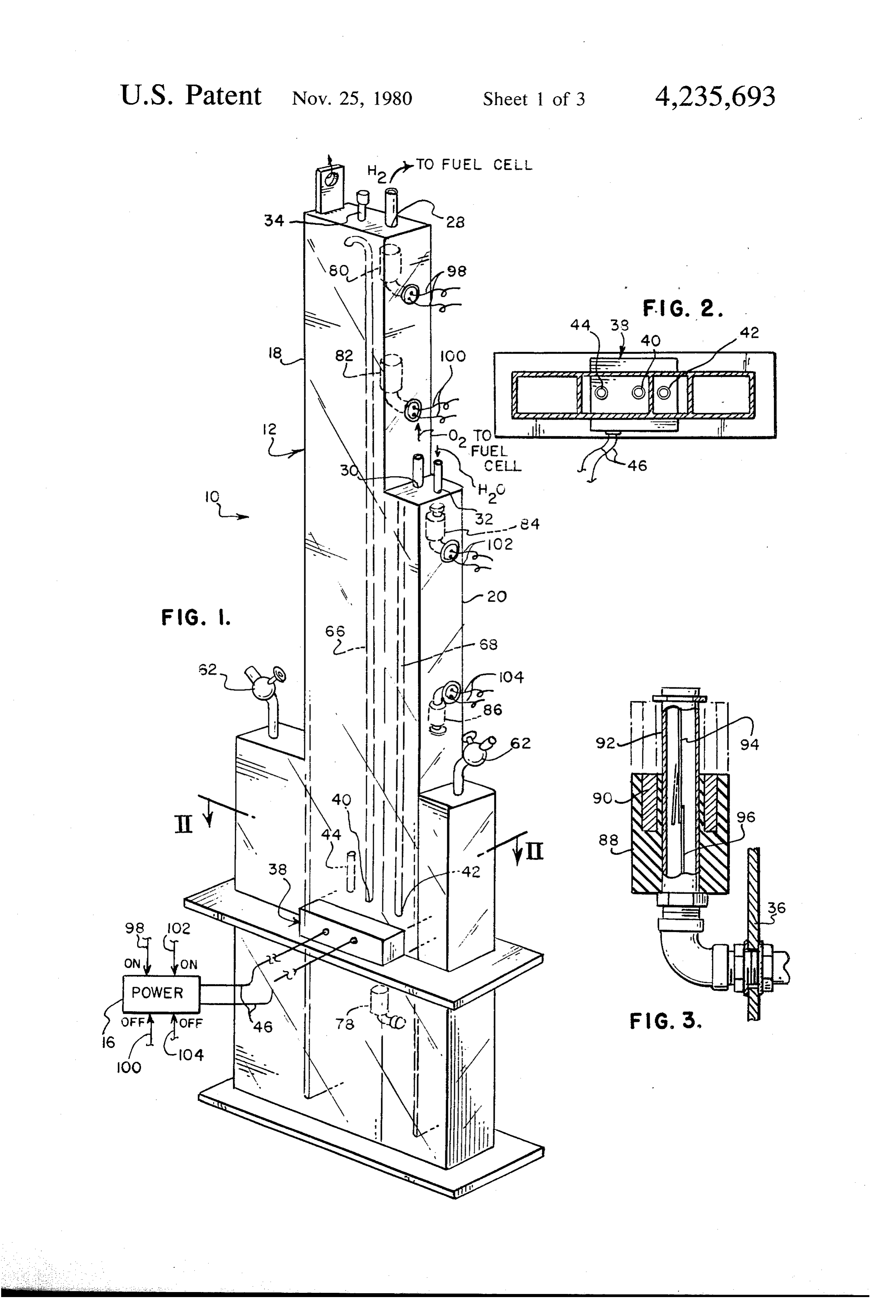
these sources is normally intermittent. There has been a 25 need for an energy device which will store intermit BRIEF DESCRIPTION OF THE DRAWINGS tently generated energy so that power will be available FIG. 1 is an isometric view of the electrolysis unit to oceanographic equipment on a demand basis. Also, feed water gas collection assembly and power source the amount of power produced by solar cells or wave therefor.
action is sometimes not sufficient to operate the remote FIG. 2 is a cross sectional view taken along plane equipment. There is a need for an energy storage device 30 II-II of FIG. 1.
which will receive small power inputs and then subse quently deliver a higher power output to operate the of a float3 isreed
FIG. an elevational view, partly in cross section, switch utilized in the electrolysis feed equipment.
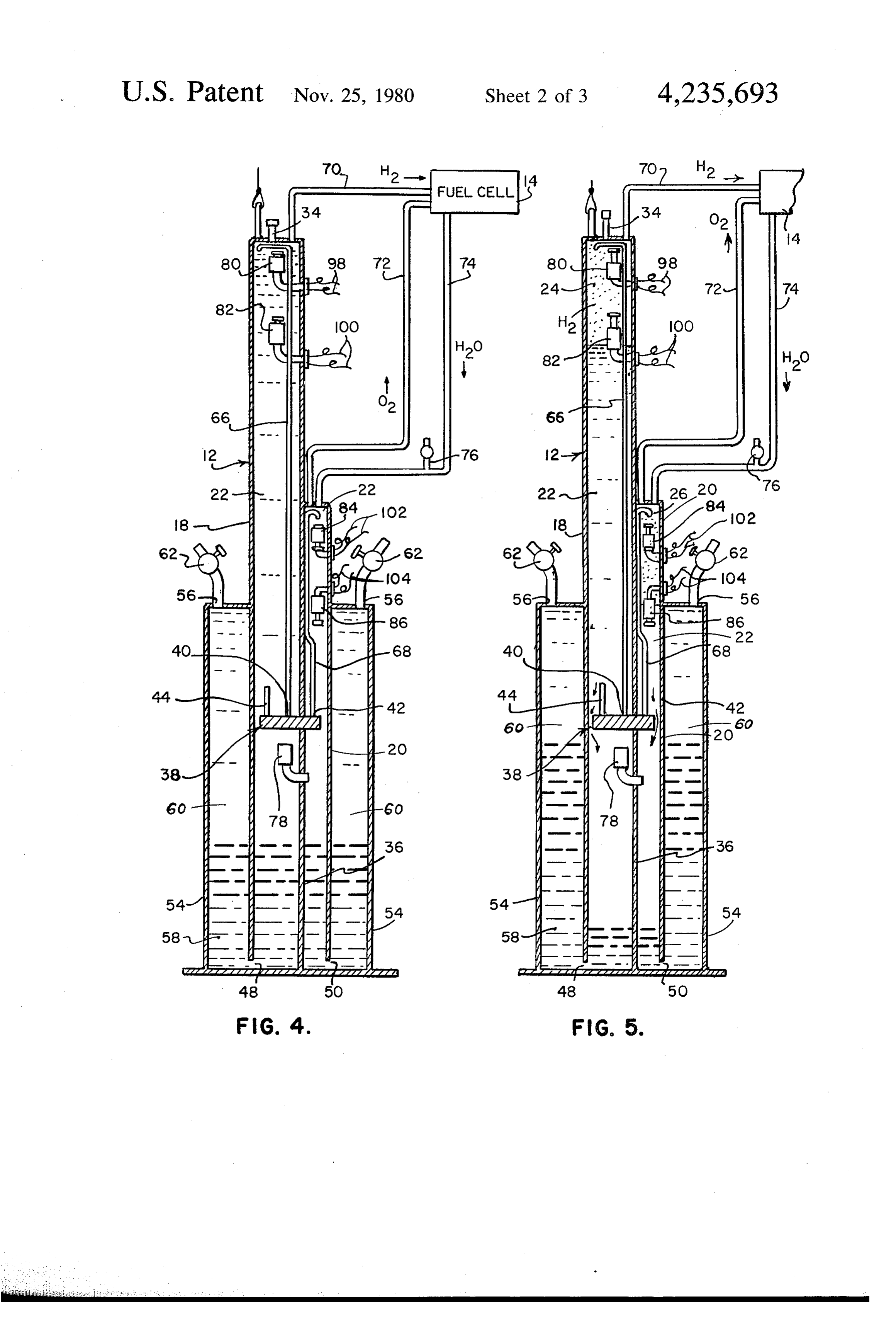
Presently, there is much interest in the storage of water gas collection assembly unit. FIG. 4 is an elevational cross sectional view of the energy from power generating utility plants during low 35 electrolysis demand periods such as at night for supplying gener the fuel cellunit in a feed water gas collection assembly and water filled mode.
ated as well as stored power during high demand peri FIG. 5 is similar to FIG. 4 except the electrolysis unit ods. Most utility plants near a body of water, such as at feed water gas collection assembly and the fuel cell is in advanced navy bases or near lakes or rivers, are not being utilized to their full potential since they are virtu 40 a gas stored mode.
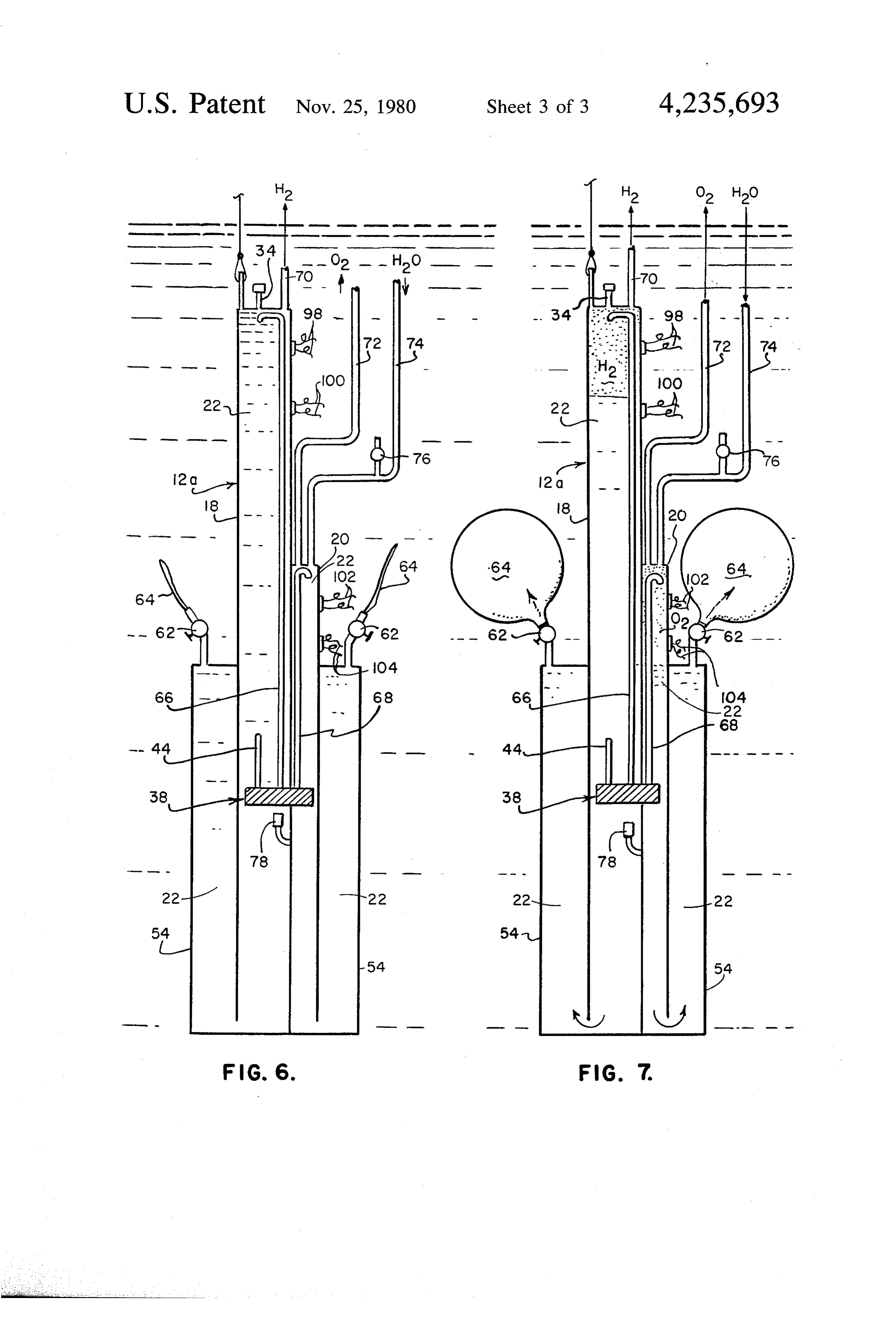
ally dormant during the nighttime. Again, a practical FIG. 6 is a modified form of the electrolysis unit feed device of storing the energy from utility plants during water gas collection assembly in an inactive mode. low demand periods is needed. FIG. 7 is the modified electrolysis unit feed water gas collection assembly in an active mode.
SUMMARY OF THE INVENTION . 45 DESCRIPTION OF THE PREFERRED The present invention provides an energy storage EMBODIMENTS apparatus which is submersible, such as in ocean water, for storing small amounts of energy to supply a larger Referring now to the drawings wherein like refer capacity when demanded. This has been accomplished ence numerals designate like or similar parts throughout by providing an electrolysis unit feed water gas collec 50 the several views there is illustrated in FIG. 1 a sub tion assembly in combination with a fuel cell. The elec mersible energy storage apparatus 10 which includes an trolysis unit feed water gas collection assembly contains electrolysis unit feed water gas collection assembly 12, a hydrogen container and an oxygen container wherein and a fuel cell 14 (see FIG. 4), which can be used to each container has a gas outlet and is capable of contain store power from a power source 16. As illustrated in ing feed water as well as hydrogen and oxygen gases 55 FIGS. 1, 4 and 5 the electrolysis unit feed water gas respectively. An electrolysis cell is provided which has collection assembly may include a hydrogen container a hydrogen outlet, an oxygen outlet, and a feed water 18, and an oxygen container 20. Each container is capa inlet. The hydrogen outlet is located in the hydrogen ble of containing feed water 22 as well as hydrogen and container, the oxygen outlet is located in the oxygen oxygen gases 24 and 26 respectively. The containers are container, and the feed water inlet is located in one of 60 preferably upstanding with the hydrogen container 18 the containers. Each of the containers has an opening to being higher than the oxygen container 20 for a purpose the submersible ambient environment so as to be pres to be explained hereinbelow. The top portions of the sure responsive thereto. A barrier device is operably containers 18 and 20 may be provided with hydrogen associated with the opening in each container for isolat and oxygen gas outlets 28 and 30 respectively. The ing feed water in the container from water in the sub 65 oxygen container may be provided with a feed water mersible environment. The fuel cell is operably con inlet 32 at its top end, and the top end of the hydrogen nected to the hydrogen and oxygen containers, and the container 18 may be provided with a feed water inlet electrical power source is operably connected to the tube 34 which may be sealed with a screw cap after the
Page 6
containers are completely filled with feed water. As the top of the oxygen container 20. In order to prevent illustrated in FIGS. 1, 4 and 5, the containers 18 and 20 absorption of these gases in the feed water a hydrogen may be rectangular in cross section and may be pro conduit 66 may be connected to the hydrogen gas outlet vided with a common wall 36. of the electrolysis unit and may extend upwardly into a An electrolysis unit 38, which may include one or top portion of the hydrogen container 18. In like man more electrolysis cells, may be provided which has a ner an oxygen conduit 68 may be connected to the hydrogen outlet 40, and oxygen outlet 42, and a water oxygen outlet 42 of the electrolysis unit and may extend inlet conduit 44. The hydrogen outlet 40 is located in upwardly into a top portion of the oxygen container 20. the hydrogen container 18, the oxygen outlet 42 is lo The hydrogen and oxygen gases are then delivered to cated in the oxygen container 20, and the feed water O the fuel cell via hydrogen and oxygen conduits 70 and inlet 44 may be located within the hydrogen container 72. Feed water generated by the fuel cell is then re 18. The electrolysis unit 38, which may be rectangular turned to the top of the oxygen container 20 via a con in shape, may sealably extend through and between the duit 74. The feed water conduit 74 may be provided hydrogen and oxygen containers 18 and 20, as illus with a valve 76 intermediate in the line for initial feed trated in FIG. 1 so that the gas outlets and feed water 15 water filling purposes.
inlet are located as described hereinabove. Further, the Below the electrolysis unit 38 a check valve 78 may electrolysis unit 38 is hermetically sealed except for its be provided in the common wall 36 between the con designed openings. A suitable electrolysis unit is the H2 tainers with the one way direction flow being from the Gen model 15EHG 1 B made by General Electric. The oxygen container 20 to the hydrogen container 18. It is electrical power source 16 is connected to the electroly 20 important that the feed water return to the oxygen sis unit 38 by leads 46. The electrical power source may container 20, that thence the feed water be appropri be of very small output capacity such as a solar cell or ately fed through the valve 78 to the hydrogen con wave generator floating on the surface of the water. tainer 18, and that the hydrogen container 18 be higher Each of the containers 18 and 20 has a respective than the oxygen container 20. The purpose of this ar opening 48 and 50 to the submersible ambient environ 25 rangment is to prevent hydrogen gas from entering the ment so as to be pressure responsive thereto. Barrier fuel cell through the oxygen line 72. Such an occur means, which will be described in detail hereinafter, are rence would most likely ruin the fuel cell. With the operatively associated with the openings 48 and 50 in aforementioned arrangement the oxygen gas pressure the containers for isolating the feed water in the con within the container 20 is greater than the hydrogen gas tainers from water in the submersible environment. pressure within the container 18 when the electrolysis The barrier means may include upstanding tanks 54 unit feed water gas collection assembly is turned off by with the hydrogen and oxygen containers 18 and 20 switches which will be described hereinbelow. extending downwardly therein. The bottom portions of Pairs of switches 80 and 82, and 84 and 86 are prefera both of the containers 18 and 20 may be in communica bly mounted in top portions of the respective containers tion with the bottom portion of tanks 54 by any suitable 35 18 and 20 for switching the power source 16 on when means such as the openings 48 and 50. The upstanding feed water has risen to a predetermined level at either of tanks 54 may also be rectangular in cross section with the top switches 80 or 82 and switching the power the containers 18 and 20 sealably extending therein. The source off when the feed water level has dropped to a top of the tank may be provided with two openings 56 lower level at either of the lower switches 82 or 86. to the submersible environment which is sea water Float reed switches, one of which is illustrated in detail when the apparatus is submerged in the ocean. in FIG. 3, may be utilized for accomplishing the switch In the embodiment illustrated in FIGS. 4 and 5 the ing functions. The reed switch may include a float 88 barrier means further includes a barrier liquid 58 which with a magnet 90 which are slidable on a sealed tube 92. isolates the feed water 22 in the containers 18 and 20 A pair of reeds 94 and 96, which are connected to the from the sea water 60 in the tanks 54. In order to accom 45 wires of the switch, are normally biased apart in an open plish this isolation the barrier fluid may be heavier than circuit condition until the magnet 90 is in juxtaposition water. A suitable barrier liquid has been found to be to the reeds to effect a closed circuit condition. As “fluorolube". The level of the barrier liquid is well illustrated in FIG. 1, wires 98 and 102 from the float below the electrolysis unit 38 when the electrolysis unit switches 80 and 84 respectively are connected to the feed water gas collection assembly 12 is filled with 50 power source 16 for turning the power source on when water, as illustrated in FIG. 4, and is even further below the feed water has risen to a predetermined level. Like the electrolysis unit 38 in the gas storage mode, as illus wise, wires 100 and 104 from the float switches 82 and trated in FIG. 5. Valves 62 may be provided for open 86 respectively are also connected to the power source ing and closing the tank openings 56, these valves being 16 for turning the power source off when the feed water in the open mode when the storage apparatus is in oper 55 level has dropped a predetermined amount in either of ation. the containers 18 or 20.
Another embodiment of the electrolysis unit feed OPERATION OF THE INVENTION water gas collection assembly 12a is illustrated in FIGS.
6 and 7. In this embodiment the hydrogen and oxygen In preparing the embodiment in FIGS. 1, 4 and 5 for containers 18 and 20 and the tanks 54 are initially com 60 operation the valves 62 may be opened and the bottom pletely filled with feed water 22. Further, the outlets of portions of the tanks 54, container 18, and container 20 the valves 62 are sealed with balloon type bladders 64. may be filled with the barrier fluid such as "Fluoro In the water filled mode the bladders 64 are in a deflated lube'58 to a predetermined level below the electrolysis condition, while in a gas storage mode the bladders 64 cell 38. The conduit 34 and the valve 76 may be opened are inflated as illustrated in FIG. 7. 65 to fill the hydrogen container 18 and the oxygen con In either embodiment when the electrolysis unit 38 is tainer 20 with distilled water to serve as feed water for operated hydrogen gas will collect in the top of the the electrolysis unit 38. Sea water or fresh water may be hydrogen container 18 and oxygen gas will collect in introduced into the top portion of the tanks 54 through
Page 7
valves 62. During transportation the entire assembly is the feed water level has dropped a predetermined kept in an upright position with all of the valves closed amount.
as well as the conduit 34. 3. An electrolysis unit feed water gas collection as When the apparatus in FIGS. 1, 4 and 5 is at the site sembly as claimed in claim 1 including: of operation, it is lowered into the water to a predeter said container being upstanding with the hydrogen mined depth with the valves 62 in an open condition. container being higher than the oxygen container. The apparatus will then operate to generate hydrogen 4. An electrolysis unit feed water gas collection as and oxygen gases in the top portions of the containers sembly as claimed in claim 3 including: 18 and 20 respectively until the bottom floats 82 and 86 a feed water check valve interconnecting the oxygen are activated to turn off the power source means 16. 10 container to the hydrogen container with the direc These hydrogen and oxygen gases are utilized by the tion of flow toward the hydrogen container. fuel cell when there is an energy demand upon the fuel 5. An electrolysis unit feed water gas collection as cell, at which time the fresh water is returned from the sembly as claimed in claim 1 wherein the barrier means fuel cell via conduit 74 to the oxygen container 20. Feed 15 includes:
upstanding tanks;
water is balanced with the hydrogen container 18 the hydrogen and oxygen containers extending into through the check valve 78, and the levels of feed water within the containers 18 and 20 continue to rise until the tanks with the bottom portions of both contain either one of the float switches 80 or 84 is activated. ers being in communication with the bottom por When this occurs, the power source 16 is turned on to tions of the tanks; and once again generate gases in the top of the containers 18 the tanks each having an opening to the submersible
environment.
In the preparation of the embodiment illustrated in 6. An electrolysis unit feed water gas collection as FIGS. 6 and 7 the entire apparatus including the con sembly the as claimed in claim 5 wherein:
fluid barrier means includes a liquid which is tainers 18 and 20, and the tanks 54 are completely filled 25 heavier than water, the liquid being located with with distilled water through the conduit 34 and the the bottom portions of the containers and the tanks. valves 76 and 62. Empty bladders 64 are then attached 7. An electrolysis unit feed water gas collection as to valves 62. All valves are kept in a closed position sembly as claimed in claim 5 wherein: until the apparatus is submerged in the water, at which the barrier means includes a bladder which is time the valves 62 are opened. The embodiment illus 30 mounted across the tank opening. trated in FIGS. 6 and 7 operates in the same manner as 8. An electrolysis unit feed water gas collection as the embodiment in FIGS. 4 and 5 except when gases are sembly as claimed in claim 7 including: generated in the containers 18 and 20 the bladders 64 switch means mounted within at least one of the con expand, as illustrated in FIG. 7, to store the displaced tainers for switching a power source on when feed feed water. 35 water has risen to a predetermined level in the Obviously, many modifications and variations of the container and switching the power source off when present invention are possible in the light of the above the feed water level as dropped a predetermined teachings, and, it is therefore understood that within the amount.
scope of the disclosed inventive concept, the invention 9. An electrolysis unit feed water gas collection as may be practiced otherwise than specifically described. sembly as claimed in claim 8 including: What is claimed is: said container being upstanding with the hydrogen 1. An electrolysis unit feed water gas collection as container being higher than the oxygen container. sembly for a water submersible energy storage appara 10. An electrolysis unit feed water gas collection tus wherein the energy storage apparatus includes the assembly as claimed in claim 9 including: collection assembly as well as a fuel cell, comprising: 45 a feed water check valve interconnecting the oxygen a hydrogen container and an oxygen container, each container to the hydrogen container with the direc container having a gas outlet and being capable of tion of flow toward the hydrogen container. containing feed water as well as hydrogen and 11. A submersible energy storage apparatus for stor oxygen gases respectively; ing energy from an electrical power source comprising: an electrolysis unit having a hydrogen outlet, an oxy 50 an electrolysis unit feed water gas collection assem gen outlet, and a feed water inlet, the hydrogen bly which includes:
outlet being located in the hydrogen container, the a hydrogen container and an oxygen container, oxygen outlet being located in the oxygen con each container having a gas outlet and being tainer, and the feed water inlet being located in one capable of containing feed water as well as hy of the containers; 55 drogen and oxygen gases respectively; each of said containers having an opening to the sub an electrolysis unit having a hydrogen outlet, an mersible ambient environment so as to be pressure oxygen outlet, and a feed water inlet, the hydro responsive thereto; and gen outlet being located in the hydrogen con barrier means operatively associated with the open tainer, the oxygen outlet being located in the ing in each container for isolating the feed water in 60 oxygen container, and the feed water inlet being the containers from water in the submersible envi located in one of the containers; Onent. each of said containers having an opening to the 2. An electrolysis unit feed water gas collection as submersible ambient environment so as to be sembly as claimed in claim 1 including: pressure responsive thereto; switch means mounted within at least one of the con 65 barrier means operatively associated with the tainers for switching a power source on when feed opening in each container for isolating the feed water has risen to a predetermined level in the water in the containers from water in the sub container and switching the power source off when mersible environment; and
Page 8
a fuel cell operatively connected to the hydrogen said containers being upstanding with the hydrogen and oxygen containers. container being higher than the oxygen container; 12. A submersible energy storage apparatus as and claimed in claim 11 including: a feed water check valve interconnecting the oxygen the gas outlet of each container being in the top of the 5 container to the hydrogen container at a location respective container and the top of the oxygen below the feed water inlet of the electrolysis unit feed water gas collection assembly with the direc container having a water inlet; tion of flow toward the hydrogen container. a plurality of conduits connecting the gas outlets and 15. A submersible storage apparatus as claimed in the water inlet of the containers to the fuel cell; and 10 claim 14 including:
a conduit connected to each respective hydrogen and an upstanding tank;
oxygen outlet of the electrolysis unit feed water gas the hydrogen and oxygen containers extending into collection assembly and extending upwardly to a the tanks with the bottom portions of both contain top portion of each respective container. ers being in communication with the bottom por 13. A submersible energy storage apparatus as 15 tion of the tanks; and claimed in claim 12 including: the tanks each having an opening to the submersible switch means located within each container above environment.
the feed water inlet of the electrolysis unit feed 16. A submersible storage apparatus as claimed in water gas collection assembly for switching the 20 the 15 claim including:
barrier means includes a liquid which is heavier power source on when the feed water in the re than water, the liquid being located with the bot spective container has risen to a predetermined tom portions of the containers and the tank. level in the respective container and for switching 17. A submersible storage apparatus as claimed in the power source off when the feed water level has claim 15 including:
dropped a predetermined amount. 25 the barrier means includes a bladder which is 14. A submersible storage apparatus as claimed in mounted across: thes: tank
opening.
claim 13 including:
Page 9
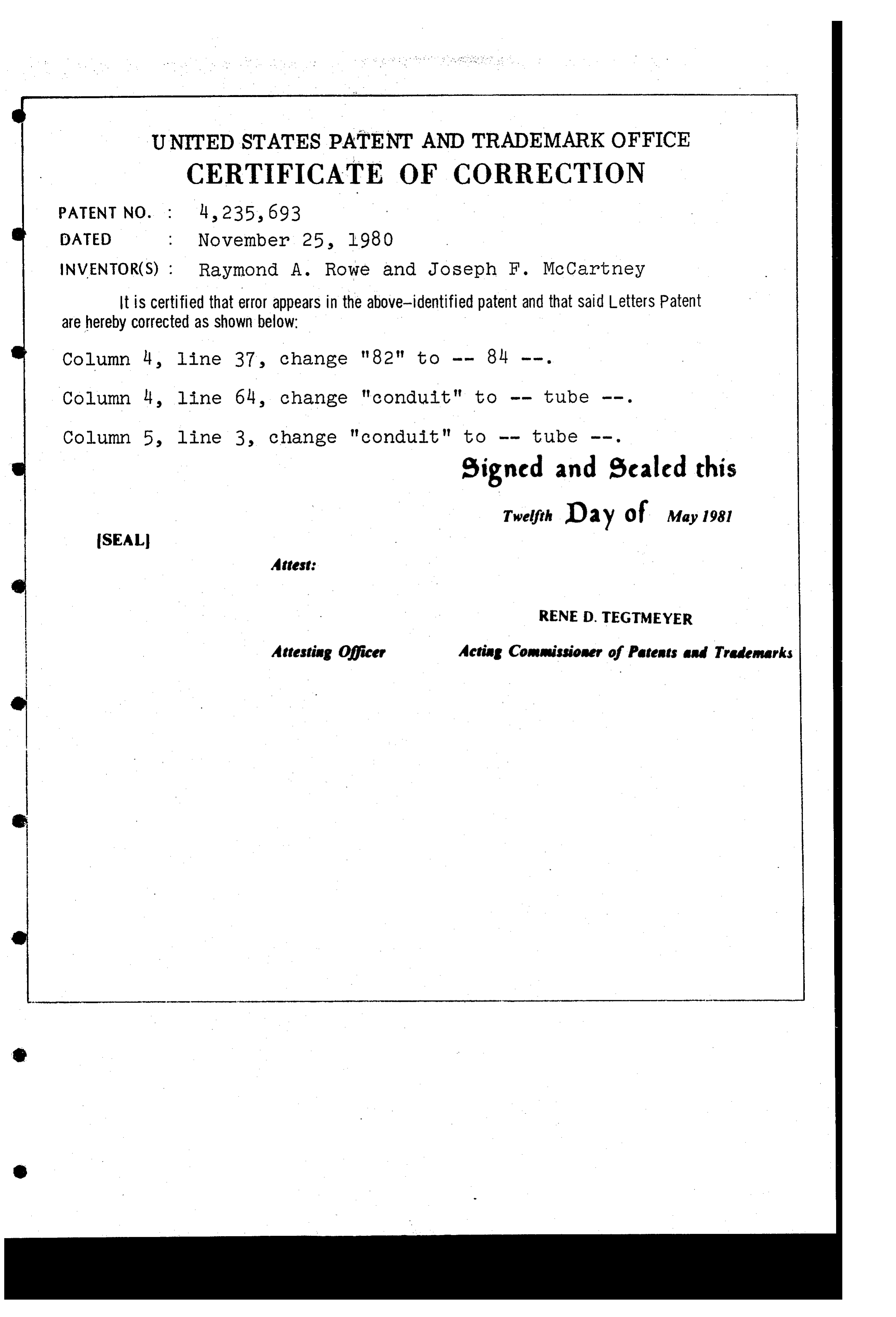
UNITED STATES PATENT AND TRADEMARK OFFICE
CERTIFICATE OF CORRECTION
INVENTOR(S) : Raymond A. Rowe and Joseph F. McCartney It is certified that error appears in the above-identified patent and that said Letters Patent are hereby Corrected as shown below:
Column 4, line 64, change "conduit" to -- tube --. Column 5, line 3, change "conduit" to -- tube --. signed and sealed this
Twelfth Day of May 1981
SEAL
Attest:
RENE D. TEGTMEYER
Attesting Officer Mcting Commissioner of Patents and Trademarks
Provenance
- Collection
- Cited prior art
- Original PDF
- patentimages.storage.googleapis.com →
- Filed
- 1979-11-09
- Pages
- 9
- Method
- pdftotext (the PDF's own text layer) + pdftoppm 300dpi page scans
- Source
- Google Patents bibliographic record
- Granted
- 1980-11-25
- Inventors
- Raymond A. Rowe; Joseph F. McCartney; US Department of Navy
- Transcribed from
- patentimages.storage.googleapis.com →