patent · US5468145
Sealed gas burner assembly
21 November 1995
Page 1 — bibliographic record
United States Patent (19) 11 Patent Number: 5,468,145 Ferlin (45) Date of Patent: Nov. 21, 1995 54 SEALED GAS BURNER ASSEMBLY 5,085,202 2/1992 Riehl.
(75) Inventor: William J. Ferlin, Plymouth, Mich. 5,119,802 6/1992 Cherry et al..
73) Assignee: Lincoln Brass Works, Inc., Detroit, 5,133,334 7/1992 Riehl. Mich. 5,139,417 8/992 Ghassemzadeh.
21 Appl. No.: 185,464 5,160,255 11/1993 Sigler.
22 Filed: Jan. 24, 1994 5,186,156 2/1993 Ferlin. 5 1. nt. C.6 - - -- - - - - a a a a - - - - - - - - - F23Q 300 FOREIGN PATENT DOCUMENTS 52 U.S. Cl. ..................... 431/266; 126/39 R; 126/39 H.
126/39 E; 431/264; 431/354 525299A2 2/1993 European Pat. Off. ............. 126/39 E 58 Field of Search ..................................... 431/266, 278, Primary Examiner-Larry Jones 431/350, 354; 126/39 E, 39 H, 39 R Attorney, Agent, or Firm-Harness, Dickey & Pierce 56 References Cited 57 ABSTRACT
burner port section defining a plurality of burner ports, a
skirted section defining an harbor, and a base section. A plate 4,565,523 1/1986 Berkelder. is secured to the base section of the burner cap and in 4,572,154 2/1986 Schweitzer. conjunction with the burner cap defines a gas chamber. An 4,626,196 12/1986 Strohrer, Jr. . electrode assembly extends through an aperture in the plate 4,627,411 12/1986 Mertler. and an aperture in the base section of the burner cap and is 4,810,188 3/1989 Kwiatek. nested in the harbor formed by the skirted section of the 4,846,671 7/1989 Kwiatek. burner port. The skirted section provides protection from 5,002,038 3/1991 Riehl. both physical damage as well as from spills.
5,083,915 1/1992 Riehl. 14 Claims, 3 Drawing Sheets
Page 2
Drawing sheet — no readable text.
Page 3
Drawing sheet — no readable text.
Page 4
Drawing sheet — no readable text.
Page 5
SEALED GAS BURNER ASSEMBLY This arrangement is not entirely reliable and addition of the integral pathways create a tool maintenance problem in the manufacturing of the burner assembly.
FIELD OF THE INVENTION The designs of external electrodes which protrude from the base and extend adjacent to the exterior sidewall, while
The present invention relates to sealed gas burners. More generating a more consistent spark pattern, suffer from the particularly, the present invention relates to a sealed gas disadvantage that the electrode is susceptible to damage burner having a uniquely integrated spark ignition device. and/or food spills due to its location on the outside of the burner body. These disadvantages of the external electrode
BACKGROUND OF THE INVENTION 10 led to the development of the internal electrode with the
Sealed gas burners are well known in the art and are internal opinion that the randomness pattern of the spark of an normally disposed around a burner opening of a range top electrode was less of a problem than the suscepti and secured in place around the periphery of the opening so bility of damage and/or food spills associated with the that any spillage of food will remain on the range top and not 15 external electrode.
pass between the burner head and the burner opening into Accordingly, there is a need for a spark ignition system the interior of the range. This type of assembly provides a which can provide a more consistent spark pattern to streamline appearance which facilitates the cleaning and increase the reliability of the primary air/gas ignition while maintenance of the range top. at the same time providing protection for the electrode from A sealed burner assembly typically includes a burner cap 20 damage and/or food spills.
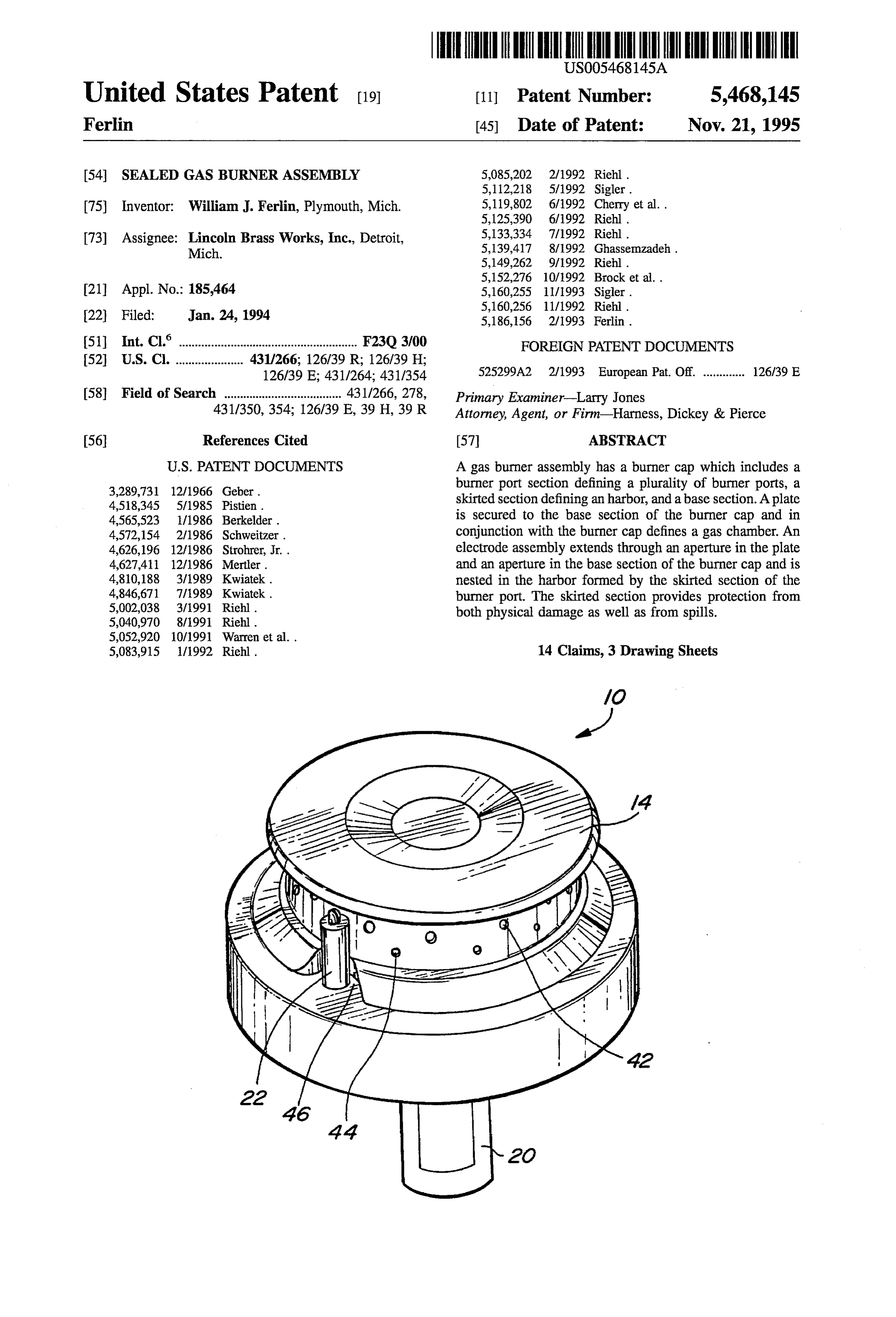
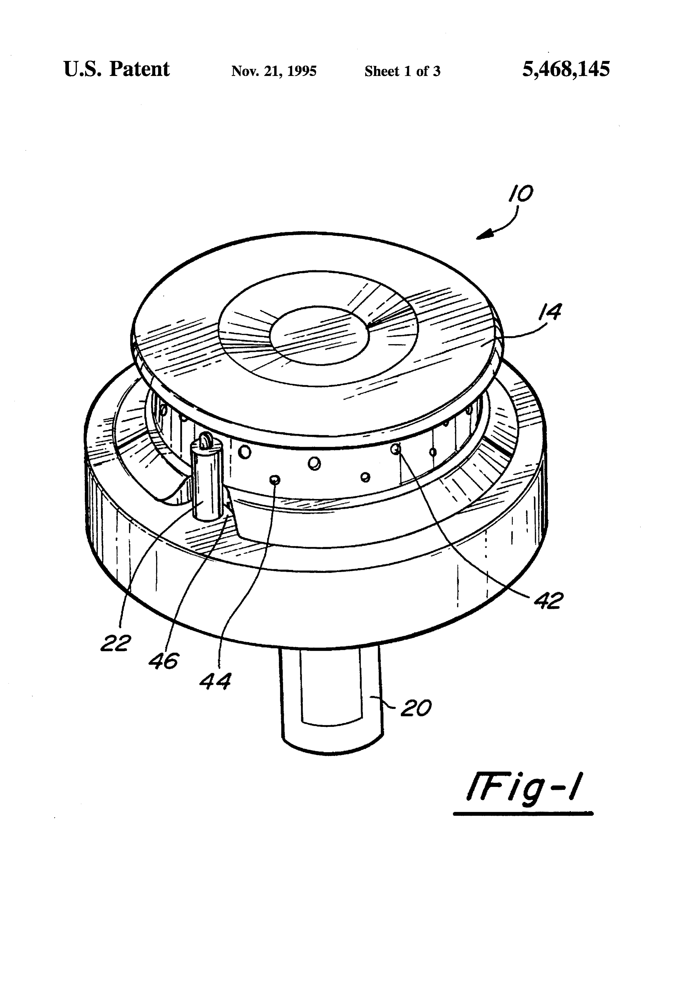
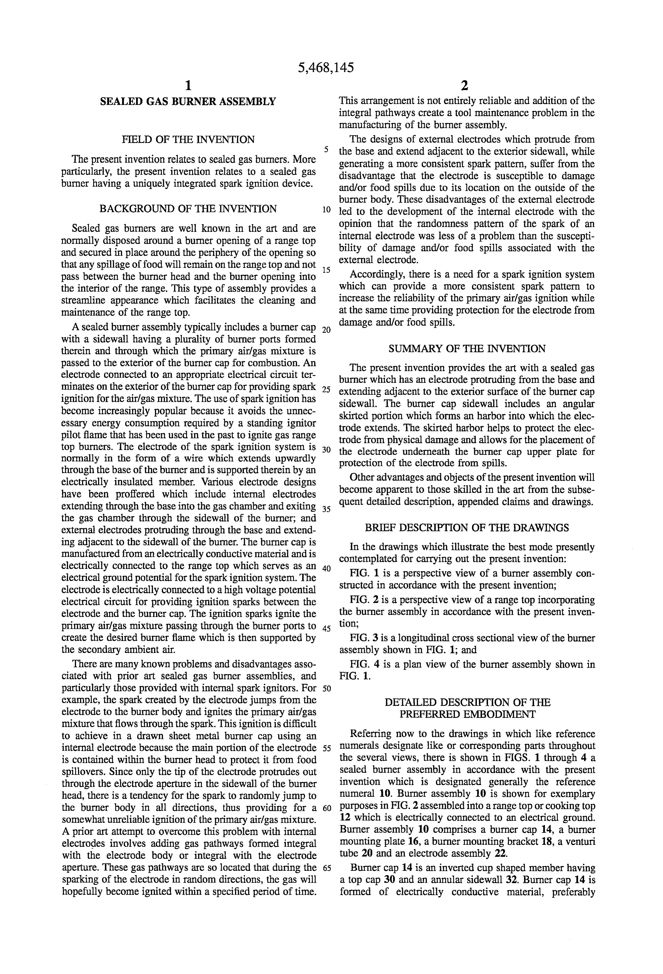
with a sidewall having a plurality of burner ports formed therein and through which the primary airlgas mixture is SUMMARY OF THE INVENTION passed to the exterior of the burner cap for combustion. An The present invention provides the art with a sealed gas electrode connected to an appropriate electrical circuit ter burner which has an electrode protruding from the base and minates on the exterior of the burner cap for providing spark 25 extending adjacent to the exterior surface of the burner cap ignition for the airlgas mixture. The use of sparkignition has sidewall. The burner cap sidewall includes an angular become increasingly popular because it avoids the unnec skirted portion which forms an harbor into which the elec essary energy consumption required by a standing ignitor trode extends. The skirted harbor helps to protect the elec pilot flame that has been used in the past to ignite gas range trode from physical damage and allows for the placement of top burners. The electrode of the spark ignition system is 30 the electrode underneath the burner cap upper plate for normally in the form of a wire which extends upwardly protection of the electrode from spills. through the base of the burner and is supported therein by an electrically insulated member. Various electrode designs become apparent to those skilled inthethepresent Other advantages and objects of invention will art from the subse have been proffered which include internal electrodes extending through the base into the gas chamber and exiting 35 quent detailed description, appended claims and drawings. the gas chamber through the sidewall of the burner; and external electrodes protruding through the base and extend BRIEF DESCRIPTION OF THE DRAWINGS ing adjacent to the sidewall of the burner. The burner cap is In the drawings which illustrate the best mode presently manufactured from an electrically conductive material and is contemplated for carrying out the present invention: electrically connected to the range top which serves as an 40 FIG. 1 is a perspective view of a burner assembly con electrical ground potential for the spark ignition system. The electrode is electrically connected to a high voltage potential structed in accordance with the present invention; electrical circuit for providing ignition sparks between the FIG. 2 is a perspective view of a range top incorporating electrode and the burner cap. The ignition sparks ignite the the burner assembly in accordance with the present inven primary airlgas mixture passing through the burner ports to 45 tion;
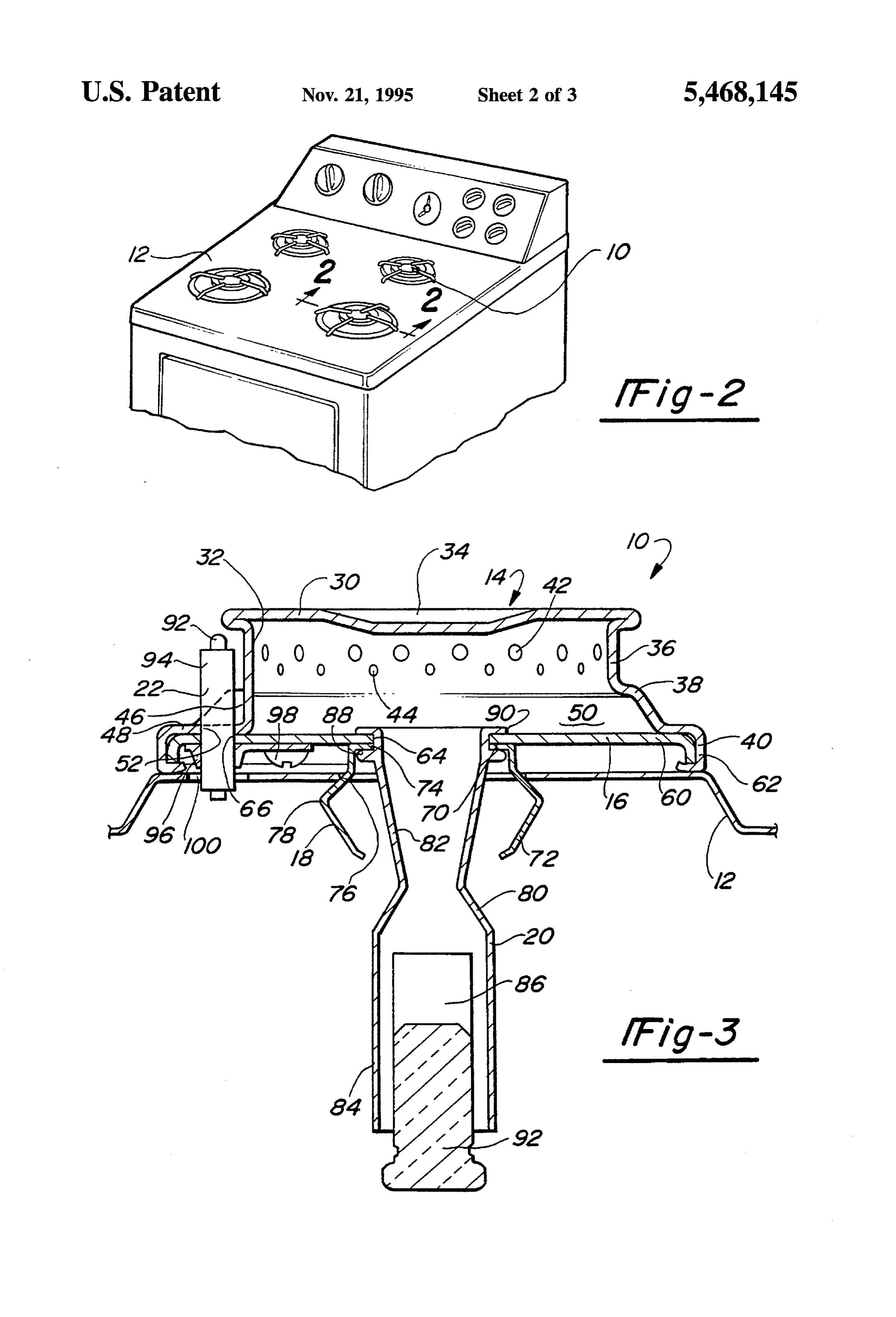
create the desired burner flame which is then supported by FIG. 3 is a longitudinal cross sectional view of the burner the secondary ambient air. assembly shown in FIG. 1; and
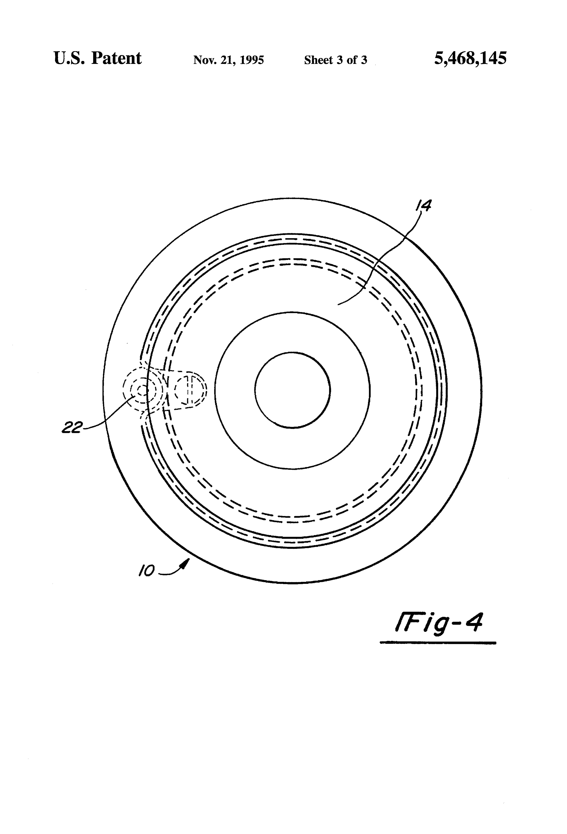
There are many known problems and disadvantages asso FIG. 4 is a plan view of the burner assembly shown in ciated with prior art sealed gas burner assemblies, and FIG. 1.
particularly those provided with internal spark ignitors. For 50 example, the spark created by the electrode jumps from the DETALED DESCRIPTION OF THE electrode to the burner body and ignites the primary air/gas PREFERRED EMBODIMENT mixture that flows through the spark. This ignition is difficult to achieve in a drawn sheet metal burner cap using an Referring now to the drawings in which like reference internal electrode because the main portion of the electrode 55 numerals designate like or corresponding parts throughout is contained within the burner head to protect it from food the several views, there is shown in FIGS. 1 through 4 a spillovers. Since only the tip of the electrode protrudes out sealed burner assembly in accordance with the present through the electrode aperture in the sidewall of the burner invention which is designated generally the reference head, there is a tendency for the spark to randomly jump to numeral 10. Burner assembly 10 is shown for exemplary the burner body in all directions, thus providing for a 60 purposes in FIG. 2 assembled into a range top or cooking top somewhat unreliable ignition of the primary airlgas mixture. 12 which is electrically connected to an electrical ground. A prior art attempt to overcome this problem with internal Burner assembly 10 comprises a burner cap 14, a burner electrodes involves adding gas pathways formed integral mounting plate 16, a burner mounting bracket 18, a venturi with the electrode body or integral with the electrode tube 20 and an electrode assembly 22. aperture. These gas pathways are so located that during the 65 Burner cap 14 is an inverted cup shaped member having sparking of the electrode in random directions, the gas will a top cap 30 and an annular sidewall 32. Burner cap 14 is hopefully become ignited within a specified period of time. formed of electrically conductive material, preferably
Page 6
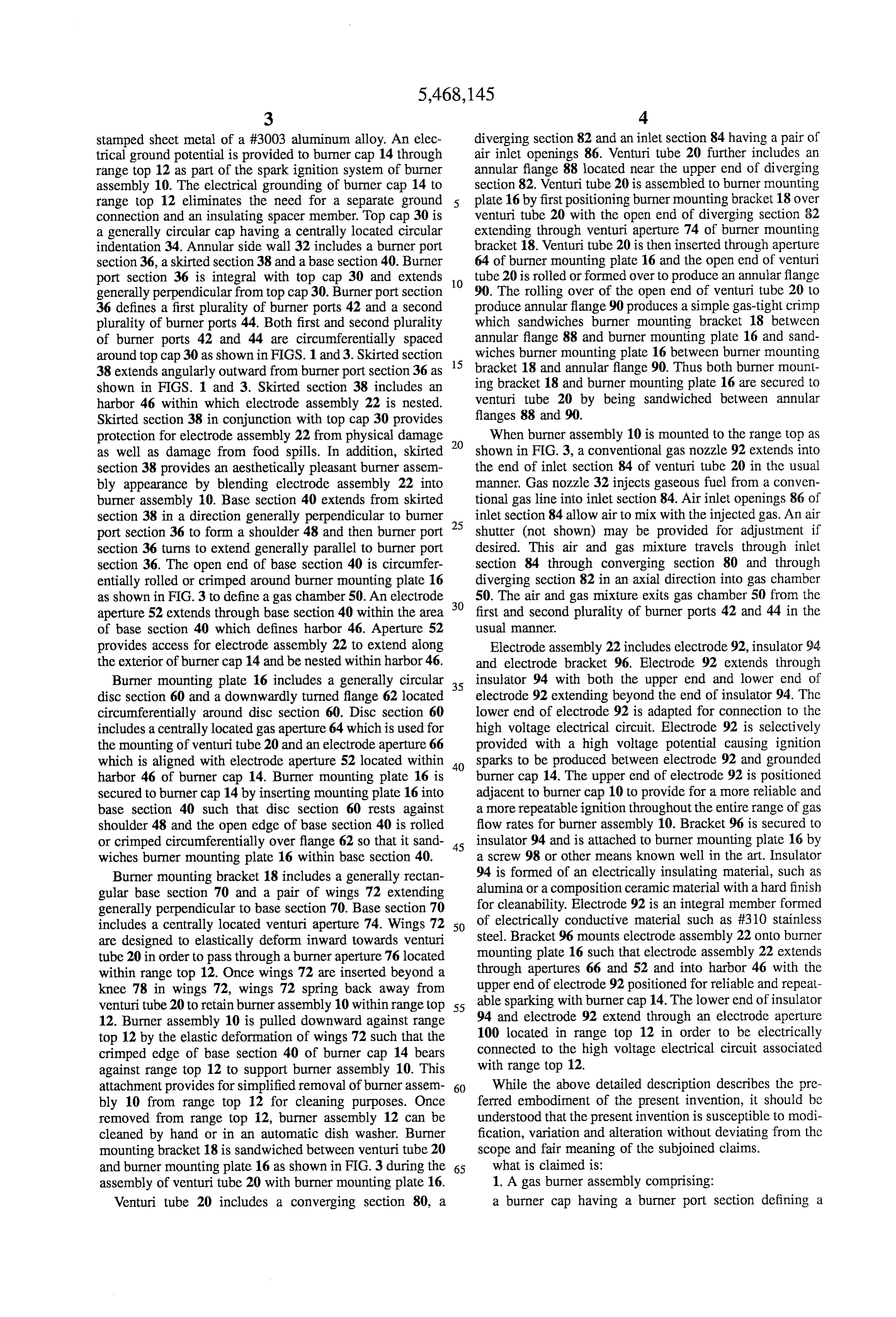
stamped sheet metal of a #3003 aluminum alloy. An elec diverging section 82 and an inlet section 84 having a pair of trical ground potential is provided to burner cap 14 through air inlet openings 86. Venturi tube 20 further includes an range top 12 as part of the spark ignition system of burner annular flange 88 located near the upper end of diverging assembly 10. The electrical grounding of burner cap 14 to section 82. Venturi tube 20 is assembled to burner mounting range top 12 eliminates the need for a separate ground plate 16 by first positioning burner mounting bracket 18 over connection and an insulating spacer member. Top cap 30 is venturi tube 20 with the open end of diverging section 82 a generally circular cap having a centrally located circular extending through venturi aperture 74 of burner mounting indentation 34. Annular side wall 32 includes a burner port bracket 18. Venturi tube 20 is then inserted through aperture section 36, a skirted section 38 and a base section 40. Burner 64 of burner mounting plate 16 and the open end of venturi port section 36 is integral with top cap 30 and extends 10 tube 20 is rolled or formed over to produce an annular flange generally perpendicular from top cap 30. Burner port section 90. The rolling over of the open end of venturi tube 20 to 36 defines a first plurality of burner ports 42 and a second produce annular flange 90 produces a simple gas-tight crimp plurality of burner ports 44. Both first and second plurality which sandwiches burner mounting bracket 18 between of burner ports 42 and 44 are circumferentially spaced annular flange 88 and burner mounting plate 16 and sand around top cap 30 as shown in FIGS. 1 and 3. Skirted section wiches burner mounting plate 16 between burner mounting 38 extends angularly outward from burner port section 36 as 15 bracket 18 and annular flange 90. Thus both burner mount shown in FIGS. 1 and 3. Skirted section 38 includes an ing bracket 18 and burner mounting plate 16 are secured to harbor 46 within which electrode assembly 22 is nested. venturi tube 20 by being sandwiched between annular Skirted section 38 in conjunction with top cap 30 provides flanges 88 and 90.
protection for electrode assembly 22 from physical damage 20 When burner assembly 10 is mounted to the range top as as well as damage from food spills. In addition, skirted shown in FIG. 3, a conventional gas nozzle 92 extends into section 38 provides an aesthetically pleasant burner assem the end of inlet Section 84 of venturi tube 20 in the usual bly appearance by blending electrode assembly 22 into manner. Gas nozzle 32 injects gaseous fuel from a conven burner assembly 10. Base section 40 extends from skirted tional gas line into inlet section 84. Air inlet openings 86 of section 38 in a direction generally perpendicular to burner inlet section 84 allow air to mix with the injected gas. An air port section 36 to form a shoulder 48 and then burner port shutter (not shown) may be provided for adjustment if section 36 turns to extend generally parallel to burner port desired. This air and gas mixture travels through inlet section 36. The open end of base section 40 is circumfer section 84 through converging section 80 and through entially rolled or crimped around burner mounting plate 16 diverging section 82 in an axial direction into gas chamber as shown in FIG. 3 to define a gas chamber 50. An electrode 30 50. The air and gas mixture exits gas chamber 50 from the aperture 52 extends through base section 40 within the area first and second plurality of burner ports 42 and 44 in the of base section 40 which defines harbor 46. Aperture 52 usual manner.
provides access for electrode assembly 22 to extend along Electrode assembly 22 includes electrode 92, insulator 94 the exterior of burner cap 14 and be nested within harbor 46. and electrode bracket 96. Electrode 92 extends through Burner mounting plate 16 includes a generally circular 35 insulator 94 with both the upper end and lower end of disc section 60 and a downwardly turned flange 62 located electrode 92 extending beyond the end of insulator 94. The circumferentially around disc section 60. Disc section 60 lower end of electrode 92 is adapted for connection to the includes a centrally located gas aperture 64 which is used for high voltage electrical circuit. Electrode 92 is selectively the mounting of venturi tube 20 and an electrode aperture 66 provided with a high voltage potential causing ignition which is aligned with electrode aperture 52 located within 40 sparks to be produced between electrode 92 and grounded harbor 46 of burner cap 14. Burner mounting plate 16 is burner cap 14. The upper end of electrode 92 is positioned secured to burner cap 14 by inserting mounting plate 16 into adjacent to burner cap 10 to provide for a more reliable and base section 40 such that disc section 60 rests against a more repeatable ignition throughout the entire range of gas shoulder 48 and the open edge of base section 40 is rolled flow rates for burner assembly 10. Bracket 96 is secured to or crimped circumferentially over flange 62 so that it sand 45 insulator 94 and is attached to burner mounting plate 16 by wiches burner mounting plate 16 within base section 40. a screw 98 or other means known well in the art. Insulator Burner mounting bracket 18 includes a generally rectan 94 is formed of an electrically insulating material, such as gular base section 70 and a pair of wings 72 extending alumina or a composition ceramic material with a hard finish generally perpendicular to base section 70. Base section 70 for cleanability. Electrode 92 is an integral member formed includes a centrally located venturi aperture 74. Wings 72 50 of electrically conductive material such as #310 stainless are designed to elastically deform inward towards venturi steel. Bracket 96 mounts electrode assembly 22 onto burner tube 20 in order to pass through a burner aperture 76 located mounting plate 16 such that electrode assembly 22 extends within range top 12. Once wings 72 are inserted beyond a through apertures 66 and 52 and into harbor 46 with the knee 78 in wings 72, wings 72 spring back away from upper end of electrode 92 positioned for reliable and repeat venturitube 20 to retain burner assembly 10 within range top 55 able sparking with burner cap 14. The lower end of insulator 12. Burner assembly 10 is pulled downward against range 94 and electrode 92 extend through an electrode aperture top 12 by the elastic deformation of wings 72 such that the 100 located in range top 12 in order to be electrically crimped edge of base section 40 of burner cap 14 bears connected to the high voltage electrical circuit associated against range top 12 to support burner assembly 10. This with range top 12.
attachment provides for simplified removal of burner assem 60 While the above detailed description describes the pre bly 10 from range top 12 for cleaning purposes. Once ferred embodiment of the present invention, it should be removed from range top 12, burner assembly 12 can be understood that the present invention is susceptible to modi cleaned by hand or in an automatic dish washer. Burner fication, variation and alteration without deviating from the mounting bracket 18 is sandwiched between venturi tube 20 scope and fair meaning of the subjoined claims. and burner mounting plate 16 as shown in FIG.3 during the 65 what is claimed is:
assembly of venturi tube 20 with burner mounting plate 16. 1. A gas burner assembly comprising: Venturi tube 20 includes a converging section 80, a a burner cap having a burner port section defining a
Page 7
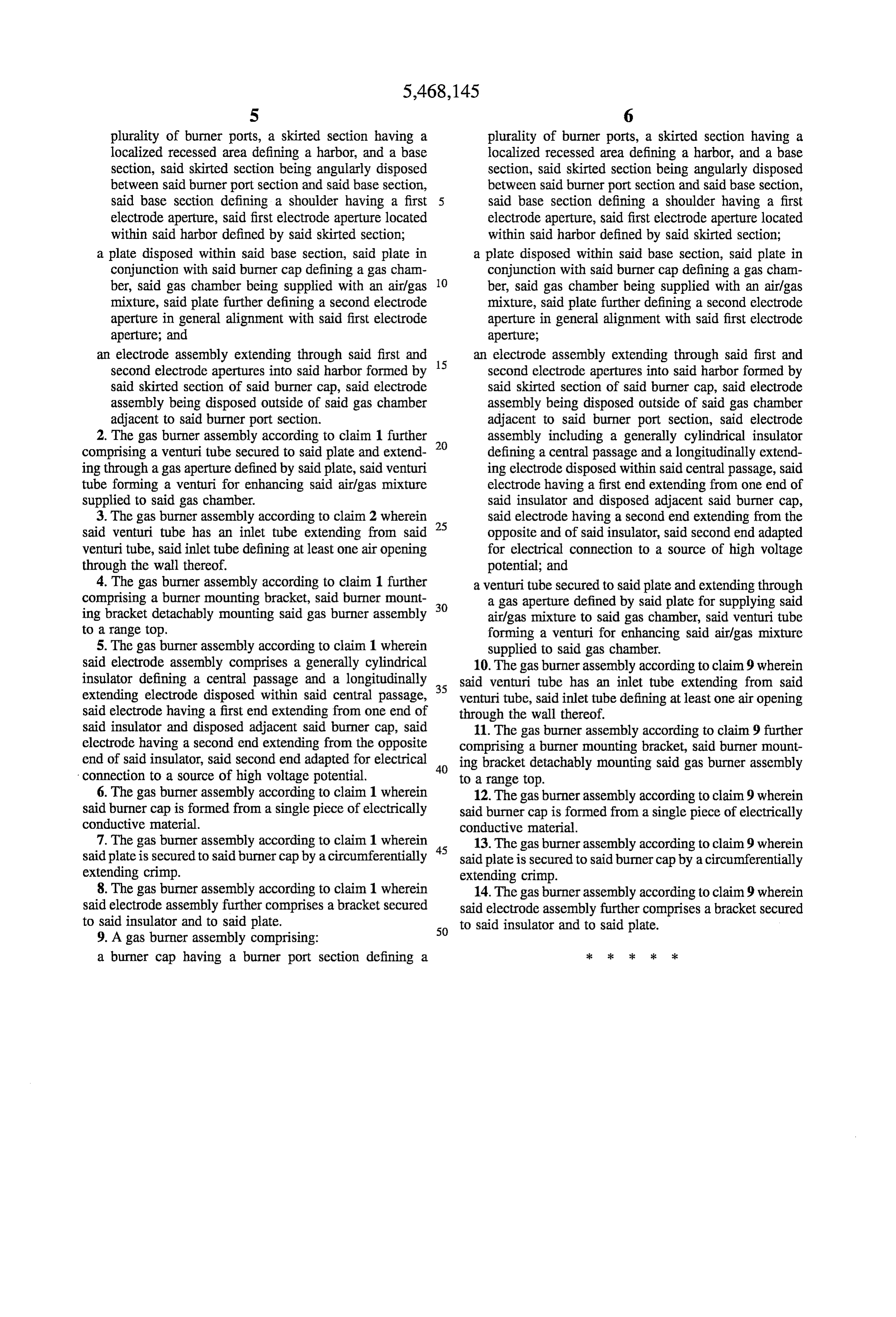
S 6 plurality of burner ports, a skirted section having a plurality of burner ports, a skirted section having a localized recessed area defining a harbor, and a base localized recessed area defining a harbor, and a base section, said skirted section being angularly disposed section, said skirted section being angularly disposed between said burner port section and said base section, between said burner port section and said base section, said base section defining a shoulder having a first said base section defining a shoulder having a first electrode aperture, said first electrode aperture located electrode aperture, said first electrode aperture located within said harbor defined by said skirted section; within said harbor defined by said skirted section; a plate disposed within said base section, said plate in a plate disposed within said base section, said plate in conjunction with said burner cap defining a gas cham conjunction with said burner cap defining a gas cham ber, said gas chamber being supplied with an air/gas O ber, said gas chamber being supplied with an air/gas mixture, said plate further defining a second electrode mixture, said plate further defining a second electrode aperture in general alignment with said first electrode aperture in general alignment with said first electrode aperture; and aperture;
an electrode assembly extending through said first and 15 an electrode assembly extending through said first and second electrode apertures into said harbor formed by second electrode apertures into said harbor formed by said skirted section of said burner cap, said electrode said skirted section of said burner cap, said electrode assembly being disposed outside of said gas chamber assembly being disposed outside of said gas chamber adjacent to said burner port section. adjacent to said burner port section, said electrode 2. The gas burner assembly according to claim 1 further 20 assembly including a generally cylindrical insulator comprising a venturi tube secured to said plate and extend defining a central passage and a longitudinally extend ing through a gas aperture defined by said plate, said venturi ing electrode disposed within said central passage, said tube forming a venturi for enhancing said airlgas mixture electrode having a first end extending from one end of supplied to said gas chamber. said insulator and disposed adjacent said burner cap, 3. The gas burner assembly according to claim 2 wherein said electrode having a second end extending from the said venturi tube has an inlet tube extending from said 25 opposite and of said insulator, said second end adapted venturi tube, said inlet tube defining at least one air opening for electrical connection to a source of high voltage through the wall thereof. potential; and 4. The gas burner assembly according to claim 1 further a venturi tube secured to said plate and extending through comprising a burner mounting bracket, said burner mount 30 a gas aperture defined by said plate for supplying said ing bracket detachably mounting said gas burner assembly air/gas mixture to said gas chamber, said venturi tube to a range top. forming a venturi for enhancing said airlgas mixture 5. The gas burner assembly according to claim 1 wherein supplied to said gas chamber.
said electrode assembly comprises a generally cylindrical 10. The gas burner assembly according to claim 9 wherein insulator defining a central passage and a longitudinally 35 said venturi tube has an inlet tube extending from said extending electrode disposed within said central passage, venturi tube, said inlet tube defining at least one air opening said electrode having a first end extending from one end of through the wall thereof.
said insulator and disposed adjacent said burner cap, said 11. The gas burner assembly according to claim 9 further electrode having a second end extending from the opposite comprising a burner mounting bracket, said burner mount end of said insulator, said second end adapted for electrical 40 ing bracket detachably mounting said gas burner assembly connection to a source of high voltage potential. to a range top.
6. The gas burner assembly according to claim 1 wherein 12. The gas burner assembly according to claim 9 wherein said burner cap is formed from a single piece of electrically said burner cap is formed from a single piece of electrically conductive material. conductive material.
7. The gas burner assembly according to claim 1 wherein 45 13. The gas burner assembly according to claim 9 wherein said plate is secured to said burner cap by a circumferentially said plate is secured to said burner cap by a circumferentially extending crimp. extending crimp.
8. The gas burner assembly according to claim 1 wherein 14. The gas burner assembly according to claim 9 wherein said electrode assembly further comprises a bracket secured said electrode assembly further comprises a bracket secured to said insulator and to said plate. 50 to said insulator and to said plate. 9. A gas burner assembly comprising:
a burner cap having a burner port section defining a
Page 8
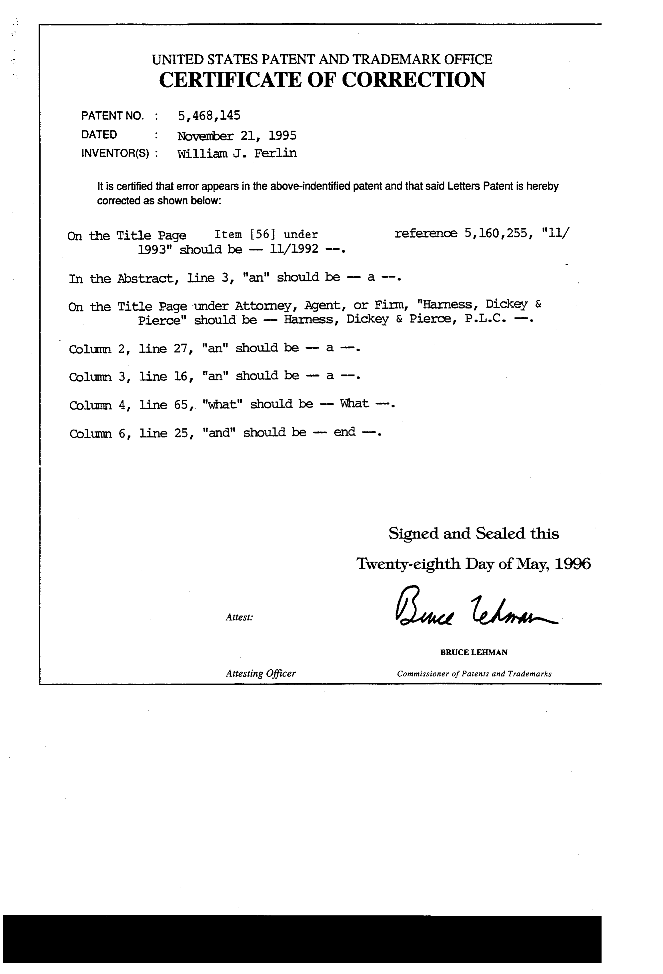
UNITED STATES PATENT ANDTRADEMARK OFFICE
CERTIFICATE OF CORRECTION
INVENTOR(S) : William J. Ferlin it is certified that error appears in the above-indentified patent and that said Letters Patent is hereby Corrected as shown below:
On the Title Page Item 56 under reference 5,160,255, "ll/
In the Abstract, line 3, "an" should be - a -i-.
On the Title Page under Attorney, Agent, or Firm, "Harness, Dickey & Pierce" should be - Harness, Dickey & Pierce, P.T.C. -- Column 2, line 27, "an" should be - a --
Column 3, line 16, "an" should be - a -.
Column 4, line 65, "what" should be - What -.
Column 6, line 25, "and" should be - end -.
Signed and Sealed this
Twenty-eighth Day of May, 1996
BRUCELEHMAN
Attesting Officer Commissioner of Patents and Trademarks
Provenance
- Collection
- Cited prior art
- Original PDF
- patentimages.storage.googleapis.com →
- Filed
- 1994-01-24
- Pages
- 8
- Method
- pdftotext (the PDF's own text layer) + pdftoppm 300dpi page scans
- Source
- Google Patents bibliographic record
- Granted
- 1995-11-21
- Inventors
- William J. Ferlin; Lincoln Brass Works Inc
- Transcribed from
- patentimages.storage.googleapis.com →