patent · US5405263
Sealed gas burner assembly
11 April 1995
Page 1 — bibliographic record
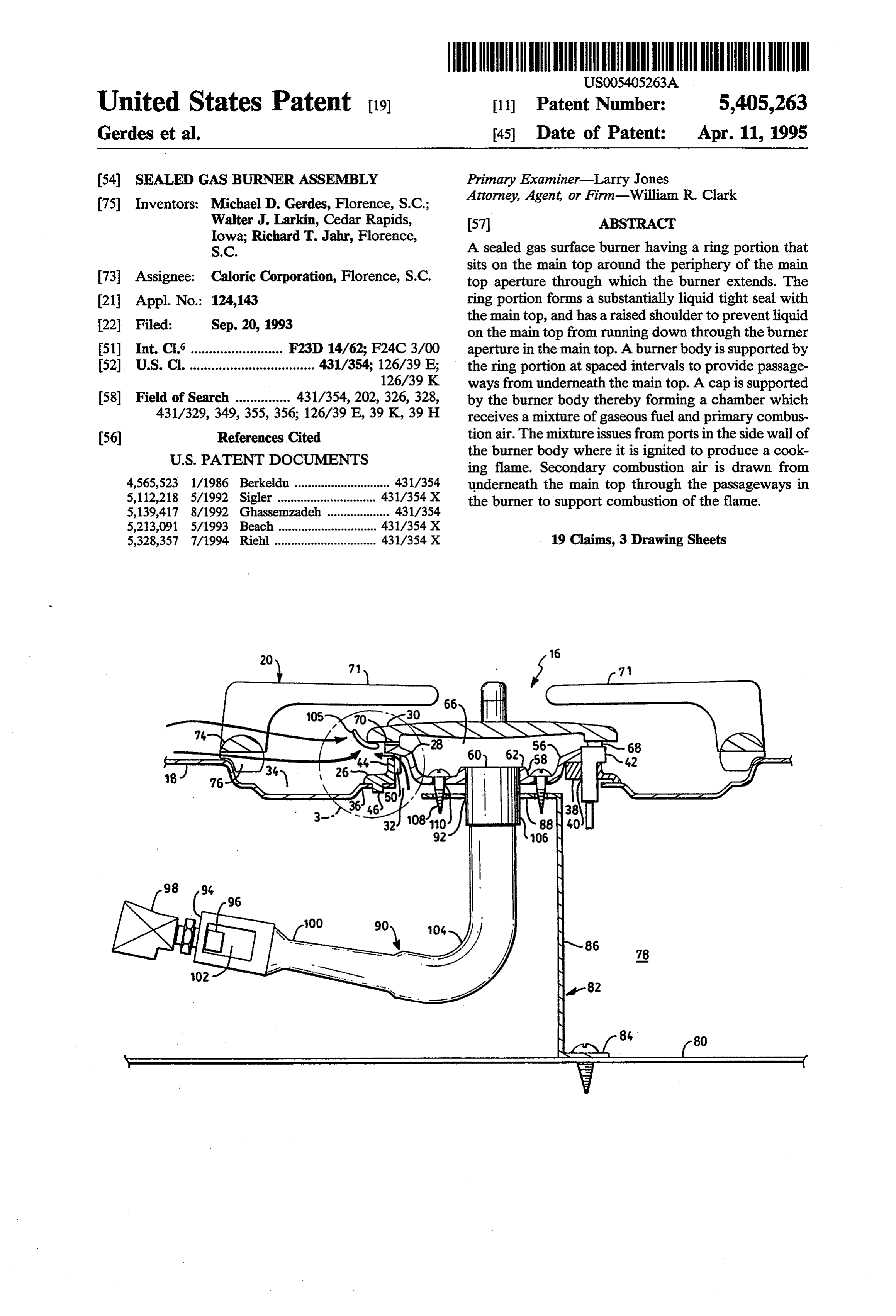
United States Patent (19) 11 Patent Number: 5,405,263 Gerdes et al. 45 Date of Patent: Apr. 11, 1995 (54) SEALED GAS BURNER ASSEMBLY Primary Examiner-Larry Jones 75 Inventors: Michael D. Gerdes, Florence, S.C.; Attorney, Agent, or Firm-William R. Clark Walter J. Larkin, Cedar Rapids, 57 ABSTRACT
Iowa; Richard T. Jahr, Florence,
S.C. A sealed gas surface burner having a ring portion that sits on the main top around the periphery of the main 73 Assignee: Caloric Corporation, Florence, S.C. top aperture through which the burner extends. The 21 Appl. No.: 124,143 ring portion forms a substantially liquid tight seal with the main top, and has a raised shoulder to prevent liquid 22 Filed: Sep. 20, 1993 on the EPtop from running down through the E. 51) Int. Cl. ......................... F23D 14/62; F24C 3/00 aperture in the main top. A burner body is supported by 52 U.S. C. .................................. 431/354; 126/39 E; the ring portion at spaced intervals to provide passage 126/39K ways from underneath the main top. A cap is supported 58) Field of Search ............... 43 1/354, 202, 326, 328, by the burner body thereby forming a chamber which 431/329,349,355, 356, 126/39 E. 39K, 39H receives a mixture of gaseous fuel and primary combus 56 References Cited tion air. The mixture issues from ports in the side wall of the burner body where it is ignited to produce a cook
4,565,523 1/1986 Berkeldu ............................. 431/354 underneath the main top through the passageways in 5,112,218 5/1992 Sigler ................ 43/354 X the burner to support combustion of the flame. 5,139,417 8/1992 Ghassemzadeh ... 431/354
5,328,357 7/1994 Riehl ............................... 431/354X 19 Claims, 3 Drawing Sheets
FS S 60 62 7 68 a-2
DiES
Page 2
Drawing sheet — no readable text.
Page 3
Drawing sheet — no readable text.
Page 4
Drawing sheet — no readable text.
Page 5
flame from underneath the main top up through the
The sealing means may comprise a ring portion
BACKGROUND OF THE INVENTION seated on the main top peripherally around the aper The field of the invention generally relates to gas 5 ture. The ring portion may comprise an upwardly ex surface burners, and more particularly relates to gas tending shoulder to provide a dam to prevent liquid on burners that are sealed to the main top to prevent spills the main top from running down through the aperture. from running down through the burner aperture in the In one embodiment, the passageway providing means main top. comprises a plurality of posts spaced at intervals around In the typical configuration, the main top of gas range 1O the ring portion to support the burner body and form has a plurality of apertures through which the surface the secondary combustion air passageways between the burners extend upwardly. For example, the throat of posts. Preferably, the burner body has a peripheral re eachburnerhead as it extends through the aperture may gion that extends above and laterally beyond the shoul have diameter of two inches, and the aperture may be der of the ring portion to prevent falling liquid from four inches in diameter. With such arrangement, there is 1. 5 directly entering the secondary air passageways. The a one inch annular concentric opening around each cap may also extend laterally beyond the peripheral burner throat, and secondary combustion air passes region of the burner body. Further, the ring portion from underneath the main top through this opening. As may have at least one downwardly extending stud re contrasted with the primary combustion air that is aspi ceived in a corresponding locator hole in the main top. rated into the venturi to mix with the fuel before com 20 The invention may also be practiced by a method of bustion, secondary combustion air is drawn to the flame fabricating a gas surface cooking appliance comprising to support combustion. One drawback of the above described arrangement is the liquid on the main top can the steps of mounting a bracket in a burner box and run down through a burner aperture thus requiring bracket. A amain connecting venturi assembly having an outlet to the top having an aperture is then posi lifting up the main top to clean underneath. For exam- 25 tioned over the burner box with the aperture aligned ple, liquid may be present on the main top as a result of with the venturioutlet. An annular seal ring is seated on a potboiling over, an accidental spill, or during clean the main top around the periphery of the aperture, and ing of the main top.
Sealed gas burners typically have a flange that is atending burner body is seated on a plurality of upwardly ex bosses of the annular ring wherein passageways sealed to the upper side of the main top. This arrange 3O are formed from underneath the main top between the ment has the advantage of preventing liquid from run bosses. Screws are driven down through the burner ning down through the burner aperture, and thereby eliminates the need to lift up the main top to clean un body into the bracket with the annular seal ring being derneath. However, the sealing of the burner to the sandwiched between the burner body and the main top periphery of the burner aperture in the main top also 35 to from a substantially liquid tight seal between the seals up the heretofore described path for secondary annular ring and the main top. A cap is then positioned combustion air. Therefore, sealed gas burners have on the burner body.
totally relied on secondary combustion air flowing With such arrangement and method, the burner is across the main top through the grates. It has been sealed to the main top to prevent spills from running determined that with this arrangement, there may not down through the aperture in the main top through be sufficient secondary combustion air to produce fa which the burner extends. The passageways up through vorable flame characteristics, especially when a large the burner provide, from underneath the main top, a pan is placed on the grate. That is, the space between supply of secondary combustion air that is independent main top and the pan has to be used not only for intro of the size of a cooking utensil that is placed on the ducing secondary combustion air, but also for exhaust 45 grate. Therefore, even when a large diameter pot is ing products of combustion. One prior art approach to used, the secondary combustion air from underneath providing good flame characteristics is to use taller the main top assures favorable flame characteristics. grates thereby increasing the space between the main That is, there is good flame stability without excessive top and a pan. However, this approach raises safety lift-off or reaching.
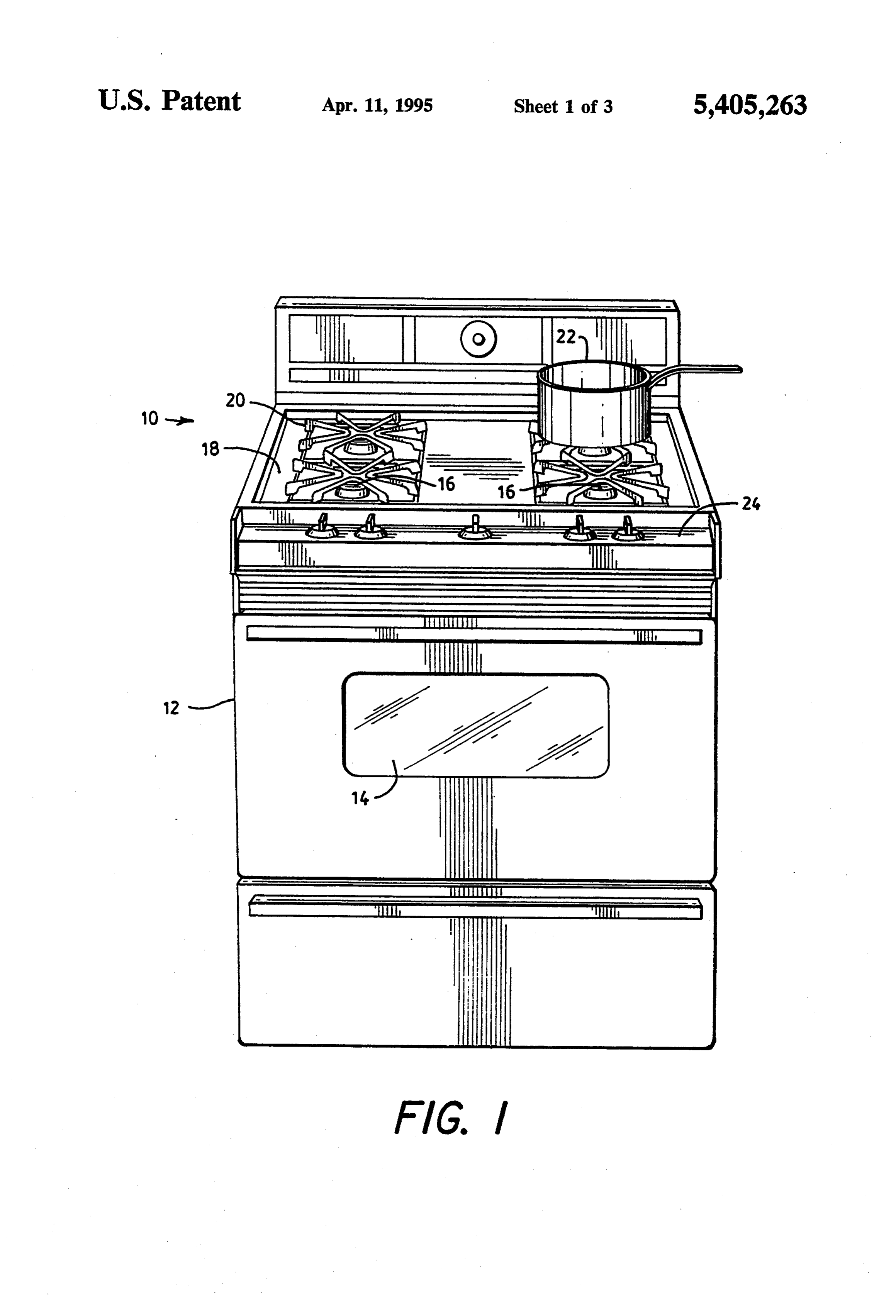
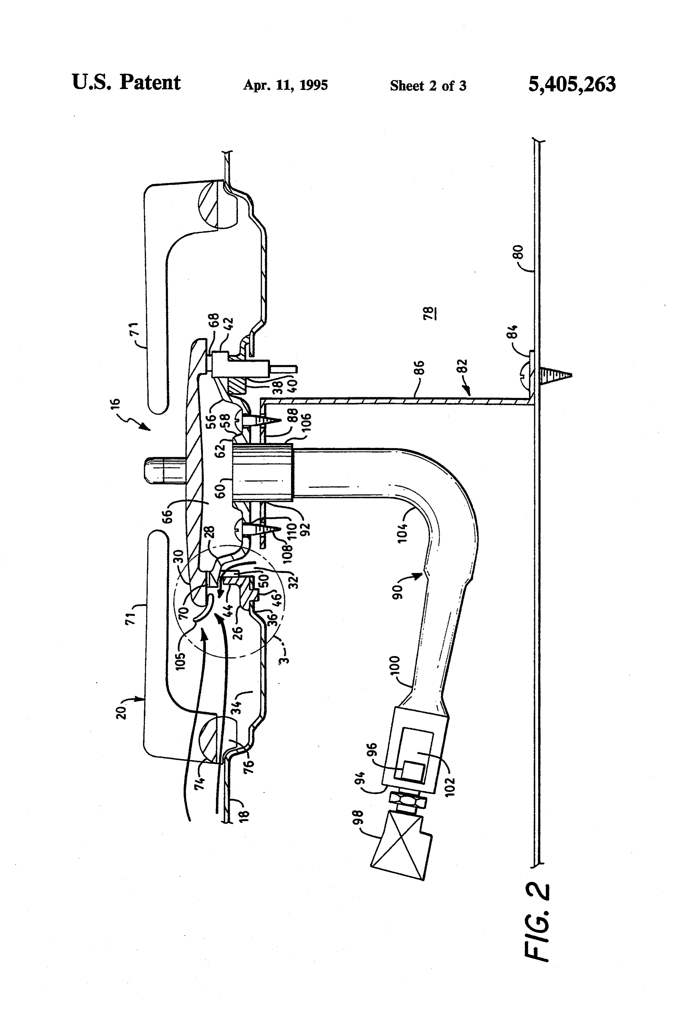
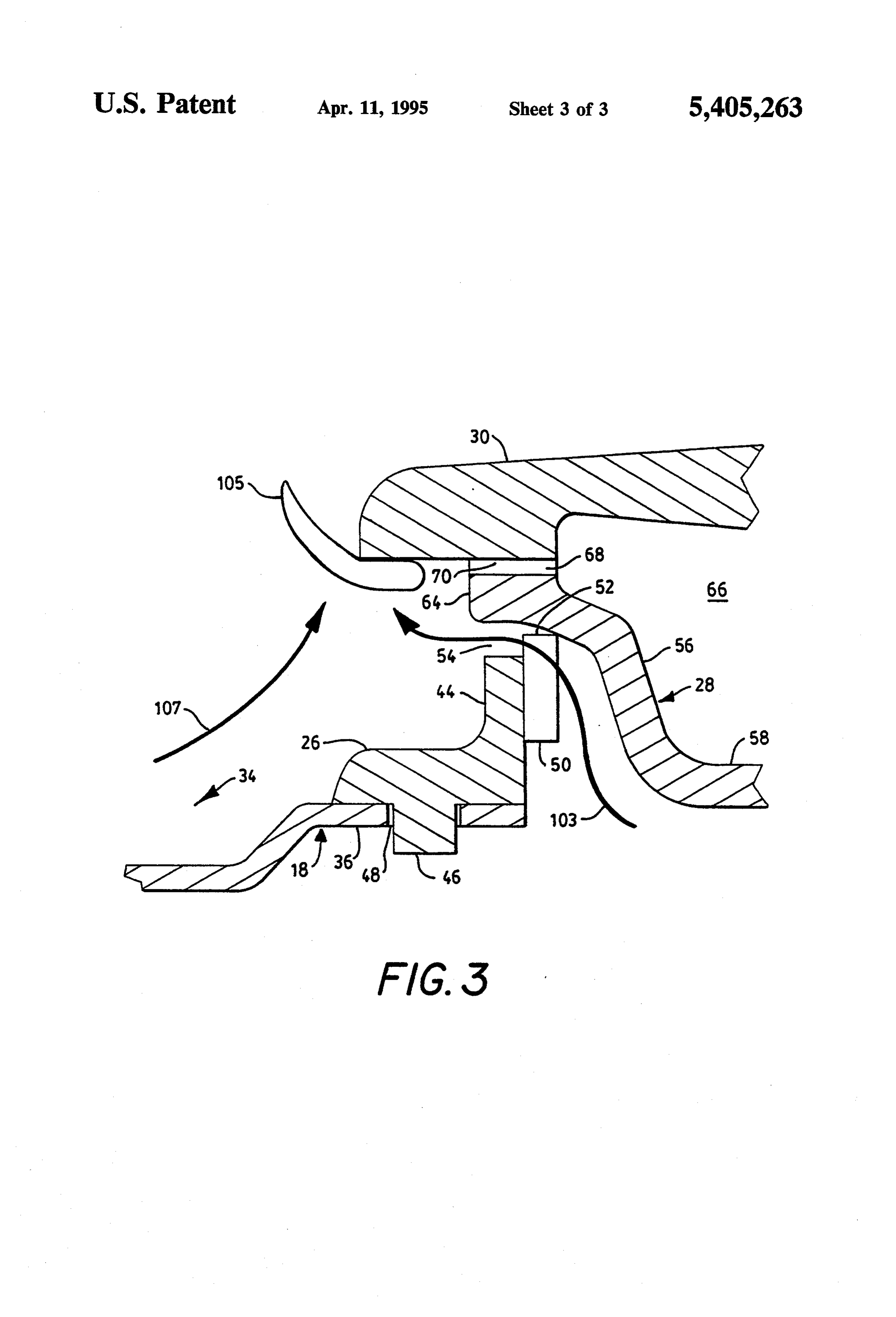
concerns in that it may be easier for a pan to tip over. 50 BRIEF DESCRIPTION OF THE DRAWINGS Another approach has been to increase the primary combustion air. However, this approach generally in The foregoing objects and advantages will be more creases the velocity of the fuel/air mixture, and the fully understood by reading the following Description flame may start to lift off or reach. of the Preferred Embodiment with reference to the 55 drawings wherein:
SUMMARY OF THE INVENTION FIG. 1 is a front view of a gas range; In accordance with the invention, a sealed gas burner FIG. 2 is a side sectioned view of one of the gas adapted for extending up through an aperture in a main surface burners of FIG. 1; and top comprises a burner body and a cap forming a cham FIG. 3 is an expanded view of the region within line ber with a plurality of ports. Means are provided for 3-3 of FIG. 2.
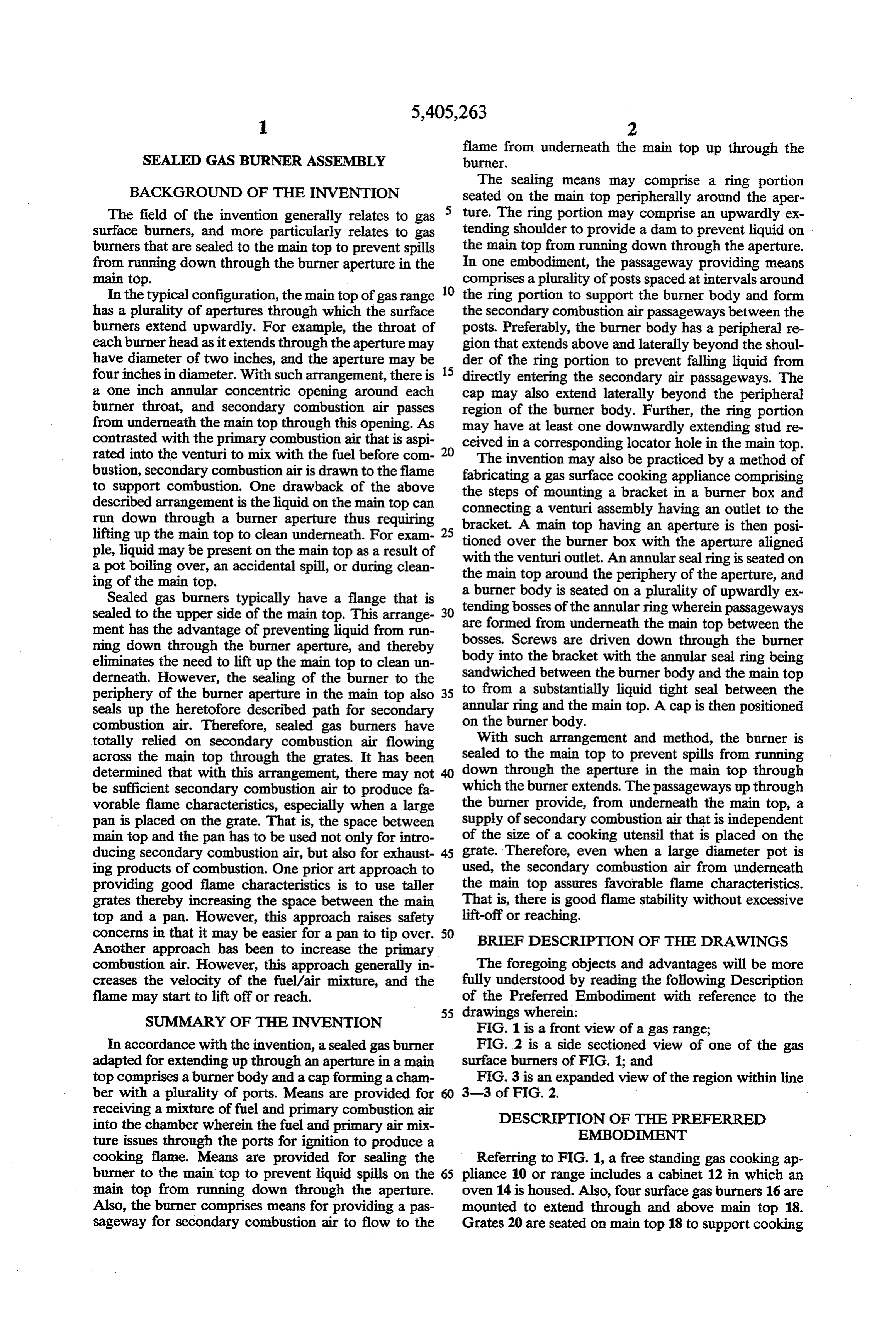
receiving a mixture of fuel and primary combustion air DESCRIPTION OF THE PREFERRED into the chamber wherein the fuel and primary air mix EMBOOMENT ture issues through the ports for ignition to produce a cooking flame. Means are provided for sealing the Referring to FIG. 1, a free standing gas cooking ap burner to the main top to prevent liquid spills on the 65 pliance 10 or range includes a cabinet 12 in which an main top from running down through the aperture. oven 14 is housed. Also, four surface gas burners 16 are Also, the burner comprises means for providing a pas mounted to extend through and above main top 18. sageway for secondary combustion air to flow to the Grates 20 are seated on main top 18 to support cooking
Page 6
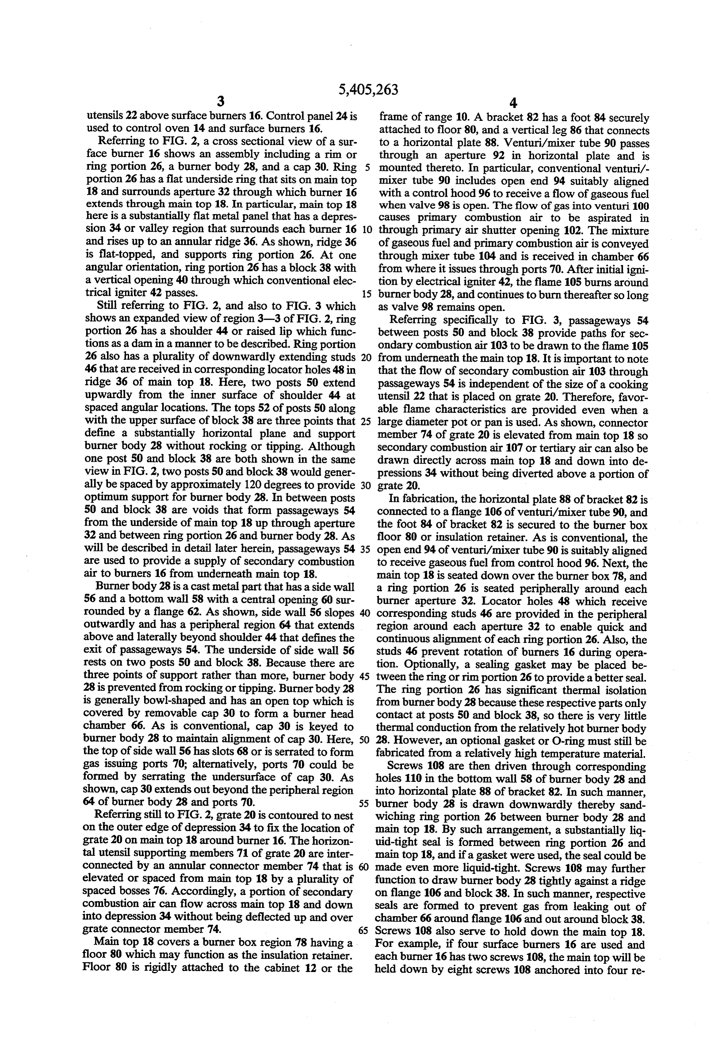
utensils 22 above surface burners 16. Control panel 24 is frame of range 10. A bracket 82 has a foot 84 securely used to control oven 14 and surface burners 16. attached to floor 80, and a vertical leg 86 that connects Referring to FIG. 2, a cross sectional view of a sur to a horizontal plate 88. Venturi/mixer tube 90 passes face burner 16 shows an assembly including a rim or through an aperture 92 in horizontal plate and is ring portion 26, a burner body 28, and a cap 30. Ring mounted thereto. In particular, conventional venturi/- portion 26 has a flat underside ring that sits on main top mixer tube 90 includes open end 94 suitably aligned 18 and surrounds aperture 32 through which burner 16 with a control hood 96 to receive a flow of gaseous fuel extends through main top 18. In particular, main top 18 when valve 98 is open. The flow of gas into venturi 100 here is a substantially flat metal panel that has a depres causes primary combustion air to be aspirated in sion 34 or valley region that surrounds each burner 16 10 through primary air shutter opening 102. The mixture and rises up to an annular ridge 36. As shown, ridge 36 of gaseous fuel and primary combustion air is conveyed is flat-topped, and supports ring portion 26. At one through mixer tube 104 and is received in chamber 66 angular orientation, ring portion 26 has a block 38 with from where it issues through ports 70. After initial igni a vertical opening 40 through which conventional elec tion by electrical igniter 42, the flame 105 burns around trical igniter 42 passes. 15 burner body 28, and continues to burn thereafter so long Still referring to FIG. 2, and also to FIG. 3 which as valve 98 remains open.
shows an expanded view of region 3-3 of FIG. 2, ring Referring specifically to FIG. 3, passageways 54 portion 26 has a shoulder 44 or raised lip which func between posts 50 and block 38 provide paths for sec tions as a dam in a manner to be described. Ring portion ondary combustion air 103 to be drawn to the flame 105 26 also has a plurality of downwardly extending studs 20 from underneath the main top 18. It is important to note 46that are received in corresponding locator holes 48 in that the flow of secondary combustion air 103 through ridge 36 of main top 18. Here, two posts 50 extend passageways 54 is independent of the size of a cooking upwardly from the inner surface of shoulder 44 at utensil 22 that is placed on grate 20. Therefore, favor spaced angular locations. The tops 52 of posts 50 along able flame characteristics are provided even when a with the upper surface of block 38 are three points that 25 large diameter pot or pan is used. As shown, connector define a substantially horizontal plane and support member 74 of grate 20 is elevated from main top 18 so burner body 28 without rocking or tipping. Although secondary combustion air 107 or tertiary air can also be one post 50 and block 38 are both shown in the same drawn directly across main top 18 and down into de view in FIG. 2, two posts 50 and block 38 would gener pressions 34 without being diverted above a portion of ally be spaced by approximately 120 degrees to provide 30 grate 20.
optimum support for burner body 28. In between posts In fabrication, the horizontal plate 88 of bracket 82 is 50 and block 38 are voids that form passageways 54 connected to a flange 106 of venturi/mixer tube 90, and from the underside of main top 18 up through aperture the foot 84 of bracket 82 is secured to the burner box 32 and between ring portion 26 and burner body 28. As floor 80 or insulation retainer. As is conventional, the will be described in detail later herein, passageways 54 35 open end 94 of venturi/mixer tube 90 is suitably aligned are used to provide a supply of secondary combustion to receive gaseous fuel from control hood 96. Next, the air to burners 16 from underneath main top 18. main top 18 is seated down over the burner box. 78, and Burner body 28 is a cast metal part that has a side wall a ring portion 26 is seated peripherally around each 56 and a bottom wall 58 with a central opening 60 sur burner aperture 32. Locator holes 48 which receive rounded by a flange 62. As shown, side wall 56 slopes corresponding studs 46 are provided in the peripheral outwardly and has a peripheral region 64 that extends region around each aperture 32 to enable quick and above and laterally beyond shoulder 44 that defines the continuous alignment of each ring portion 26. Also, the exit of passageways 54. The underside of side wall 56 studs 46 prevent rotation of burners 16 during opera rests on two posts 50 and block 38. Because there are tion. Optionally, a sealing gasket may be placed be three points of support rather than more, burner body 45 tween the ring or rim portion 26 to provide a better seal. 28 is prevented from rocking or tipping. Burner body 28 The ring portion 26 has significant thermal isolation is generally bowl-shaped and has an open top which is from burner body 28 because these respective parts only covered by removable cap 30 to form a burner head contact at posts 50 and block 38, so there is very little chamber 66. As is conventional, cap 30 is keyed to thermal conduction from the relatively hot burner body burner body 28 to maintain alignment of cap 30. Here, 50 28. However, an optional gasket or O-ring must still be the top of side wall 56 has slots 68 or is serrated to form fabricated from a relatively high temperature material. gas issuing ports 70; alternatively, ports 70 could be Screws 108 are then driven through corresponding formed by serrating the undersurface of cap 30. As holes 110 in the bottom wall 58 of burner body 28 and shown, cap 30 extends out beyond the peripheral region into horizontal plate 88 of bracket 82. In such manner, 64 of burner body 28 and ports 70. 55 burner body 28 is drawn downwardly thereby sand Referring still to FIG. 2, grate 20 is contoured to nest wiching ring portion 26 between burner body 28 and on the outer edge of depression 34 to fix the location of main top 18. By such arrangement, a substantially liq grate 20 on main top 18 around burner 16. The horizon uid-tight seal is formed between ring portion 26 and talutensil supporting members 71 of grate 20 are inter main top 18, and if a gasket were used, the seal could be connected by an annular connector member 74 that is 60 made even more liquid-tight. Screws 108 may further elevated or spaced from main top 18 by a plurality of function to draw burner body 28 tightly against a ridge spaced bosses 76. Accordingly, a portion of secondary on flange 106 and block 38. In such manner, respective combustion air can flow across main top 18 and down seals are formed to prevent gas from leaking out of into depression 34 without being deflected up and over chamber 66 around flange 106 and out around block 38. grate connector member 74. 65 Screws 108 also serve to hold down the main top 18. Main top 18 covers a burner box region 78 having a For example, if four surface burners 16 are used and floor 80 which may function as the insulation retainer. each burner 16 has two screws 108, the main top will be Floor 80 is rigidly attached to the cabinet 12 or the held down by eight screws 108 anchored into four re
Page 7
spective brackets 82 mounted to insulation retainer or shoulder to provide a dam to prevent liquid on said burner box floor 80. Cap 30 is conventionally keyed to main top from running down through said aperture. be removably seated on burner body 28. The fabrication 4. The sealed gas burner recited in claim 3 wherein process is then completed by placing grate 20 around said passageway providing means comprises a plurality burner 16. of posts spaced at intervals around said ring portion to In operation, burner 16 is substantially sealed to main support said burner body and form said secondary air top 18, so there is essentially no reason to have to re passageways between said posts.
verse the heretofore described fabrication steps to gain 5. The sealed gas burner recited in claim 4 wherein access underneath the main top 18 such as for cleaning. said burner body has a peripheral region extending That is, any liquid on the main top 18 such as by boiling 10 above and laterally beyond said shoulder of said ring over, spills or cleaning, remains on the main top 18 for portion to prevent falling liquid from entering said sec clean-up without running down through burner aper ondary air passageways.
ture 32. Typically, the liquid collects in depression 34 6. The sealed gas burner recited in claim 5 wherein and is retained there by the dam formed by the com 15 said cap extends laterally beyond said peripheral region bined height of ridge 36 and shoulder 44. Therefore, the of said burner body.
liquid can be cleaned up using a sponge or the like. 7. The sealed gas burner recited in claim 2 wherein Further, the peripheral region 64 of burner body 28 said ring portion has at least one downwardly extending extends above and laterally beyond the entrance to stud received in a corresponding locator hole in said passageways 54 so falling liquid does not directly enter 20 main top.
passageways 54. As is conventional, cap 30 extends 8. A sealed gas burner adapted for extending up laterally beyond burner body 28 so that falling liquid 1ng: through an aperture in a main top, said burner compris does not directly enter ports 70, or passageways 54.
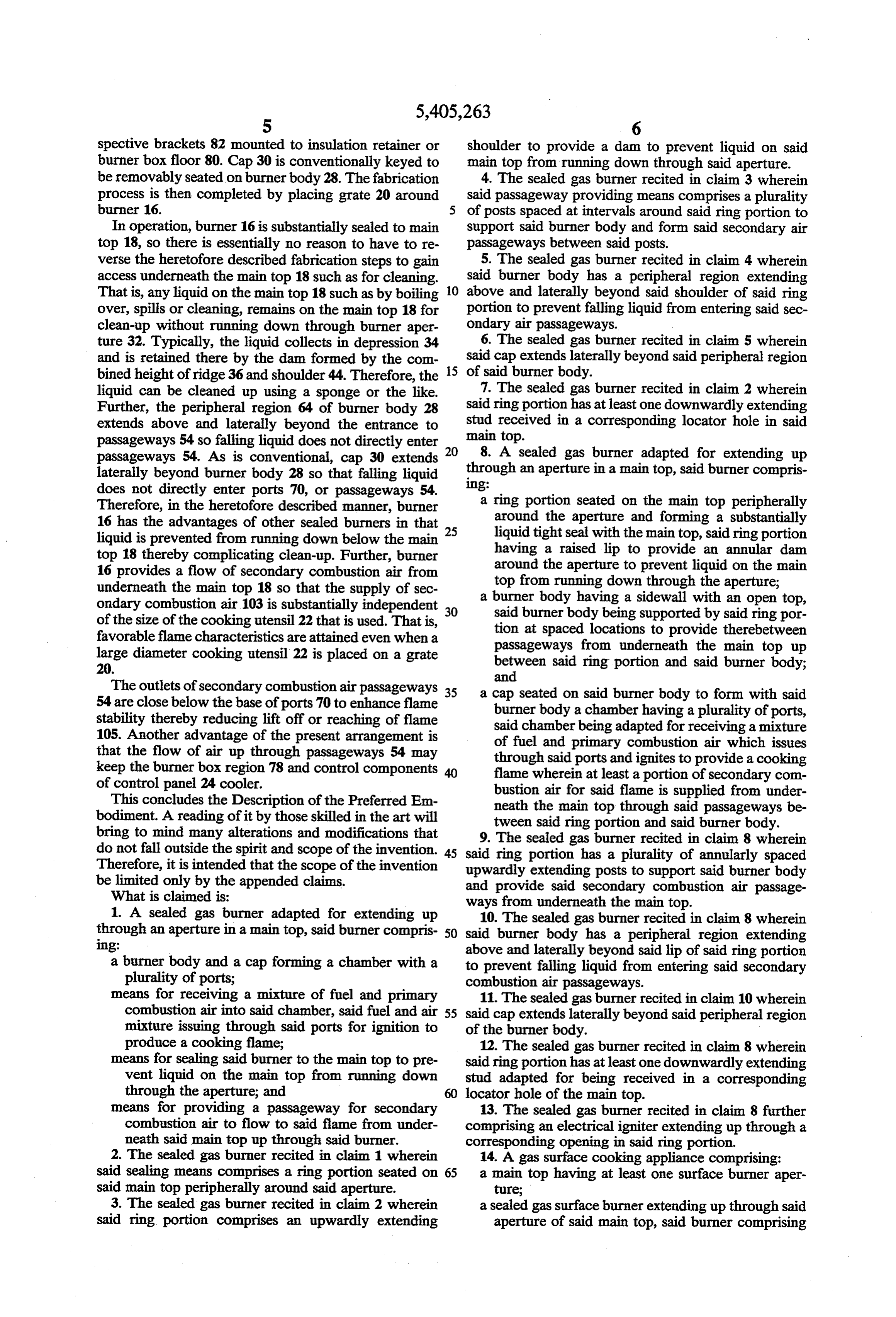
Therefore, in the heretofore described manner, burner a ring portion seated on the main top peripherally 16 has the advantages of other sealed burners in that around the aperture and forming a substantially liquid is prevented from running down below the main 25 liquid tight seal with the main top, said ring portion top 18 thereby complicating clean-up. Further, burner having a raised lip to provide an annular dam 16 provides a flow of secondary combustion air from around the aperture to prevent liquid on the main underneath the main top 18 so that the supply of sec top from running down through the aperture; ondary combustion air 103 is substantially independent 30 a burner said body having a sidewall with an open top, burner body being supported by said ring por of the size of the cooking utensil 22 that is used. That is, tion at spaced locations to provide therebetween favorable flame characteristics are attained even when a large diameter cooking utensil 22 is placed on a grate passageways from underneath the main top up 20. between said ring portion and said burner body; and
The outlets of secondary combustion air passageways 35 a cap seated on said burner body to form with said 54 are close below the base of ports 70 to enhance flame burner body a chamber having a plurality of ports, stability thereby reducing lift off or reaching of flame said chamber being adapted for receiving a mixture 105. Another advantage of the present arrangement is of fuel and primary combustion air which issues that the flow of air up through passageways 54 may through said ports and ignites to provide a cooking keep the burner box region 78 and control components flame wherein at least a portion of secondary com of control panel 24 cooler. bustion air for said flame is supplied from under This concludes the Description of the Preferred Em neath the main top through said passageways be bodiment. A reading of it by those skilled in the art will tween said ring portion and said burner body. bring to mind many alterations and modifications that do not fall outside the spirit and scope of the invention. 45 said The 9. sealed gas burner recited in claim 8 wherein ring portion has a plurality of annularly spaced
Therefore, it is intended that the scope of the invention upwardly extending posts to support said burner body be limited only by the appended claims. and provide said secondary combustion air passage What is claimed is: ways from underneath the main top. 1. A sealed gas burner adapted for extending up through an aperture in a main top, said burner compris 50 said10.burner
The sealed gas burner recited in claim 8 wherein body has a peripheral region extending 1ng: above and laterally beyond said lip of said ring portion a burner body and a cap forming a chamber with a to prevent falling liquid from entering said secondary plurality of ports; combustion air passageways.
means for receiving a mixture of fuel and primary 11. The sealed gas burner recited in claim 10 wherein combustion air into said chamber, said fuel and air 55 said cap extends laterally beyond said peripheral region mixture issuing through said ports for ignition to of the burner body.
produce a cooking flame; 12. The sealed gas burner recited in claim 8 wherein means for sealing said burner to the main top to pre said ring portion has at least one downwardly extending vent liquid on the main top from running down stud adapted for being received in a corresponding through the aperture; and locator hole of the main top.
means for providing a passageway for secondary 13. The sealed gas burner recited in claim 8 further combustion air to flow to said flame from under comprising an electrical igniter extending up through a neath said main top up through said burner. corresponding opening in said ring portion. 2. The sealed gas burner recited in claim 1 wherein 14. A gas surface cooking appliance comprising: said sealing means comprises a ring portion seated on 65 a main top having at least one surface burner aper said main top peripherally around said aperture. ture;
3. The sealed gas burner recited in claim 2 wherein a sealed gas surface burner extending up through said said ring portion comprises an upwardly extending aperture of said main top, said burner comprising
Page 8
an annular seal member seated on said main top eral region extending above and laterally beyond said peripherally around said aperture and forming a raised shoulder of said seal member to prevent falling substantially liquid tight seal with said main top, liquid from entering said secondary combustion air said annular seal member having a raised shoulder passageways.
forming an annular dam to prevent liquid on said 5 18. The gas surface cooking appliance recited in main top from running down through said aperture claim 14 further comprising a support bracket extending in said main top; under said burner body, said burner body being screwed said burner further comprising a burner body and cap down to said bracket to secure said burner body to said forming a chamber with ports, said burner body cooking appliance with said seal member sandwiched being supported by said annular seal member at 10 between said burner body and said main top. spaced locations around said seal member to form 19. A method of fabricating a gas surface cooking passageways from underneath said main top be appliance comprising the steps of:
tween said spaced locations; connecting a venturi assembly having an outlet to a means for supplying a mixture of fuel and primary bracket;
combustion air to said chamber, said mixture issu 15 mounting said bracket in a burner box; ing from said ports; and positioning a main top having an aperture aligned means for igniting said mixture issuing from said ports with said venturi outlet over said burner box; to produce a cooking flame that receives secondary seating an annular seal ring on said main top around combustion air through said passageways from the periphery of said aperture; underneath said main top. 20 seating a burner body of a burner on a plurality of 15. The gas surface cooking appliance recited in upwardly extending bosses of said annular ring claim 14 wherein said burner body is supported by a wherein passageways from underneath said main plurality of posts extending upwardly from said annular top are formed through said aperture and up be seal member at said spaced locations, said passageways tween said bosses;
being formed by voids between said posts. 25 driving screws down through said burner body and 16. The gas surface cooking appliance recited in into said bracket wherein said annual seal ring is claim 14 wherein said seal member comprises a down sandwiched between said burner body and said wardly extending stud received in a corresponding main top to form a substantially liquid tight seal locator hole in said main top. between said annular ring and said main top; and 17. The gas surface cooking appliance recited in 30 positioning a cap on said burner body. claim 14 wherein said burner body comprises a periph x2 k sk k
Provenance
- Collection
- Cited prior art
- Original PDF
- patentimages.storage.googleapis.com →
- Filed
- 1993-09-20
- Pages
- 8
- Method
- pdftotext (the PDF's own text layer) + pdftoppm 300dpi page scans
- Source
- Google Patents bibliographic record
- Granted
- 1995-04-11
- Inventors
- Michael D. Gerdes; Walter J. Larkin; Richard T. Jahr; Caloric Corp
- Transcribed from
- patentimages.storage.googleapis.com →