patent · US5448889
Method of and apparatus for producing power using compressed air
12 September 1995
Page 1 — bibliographic record
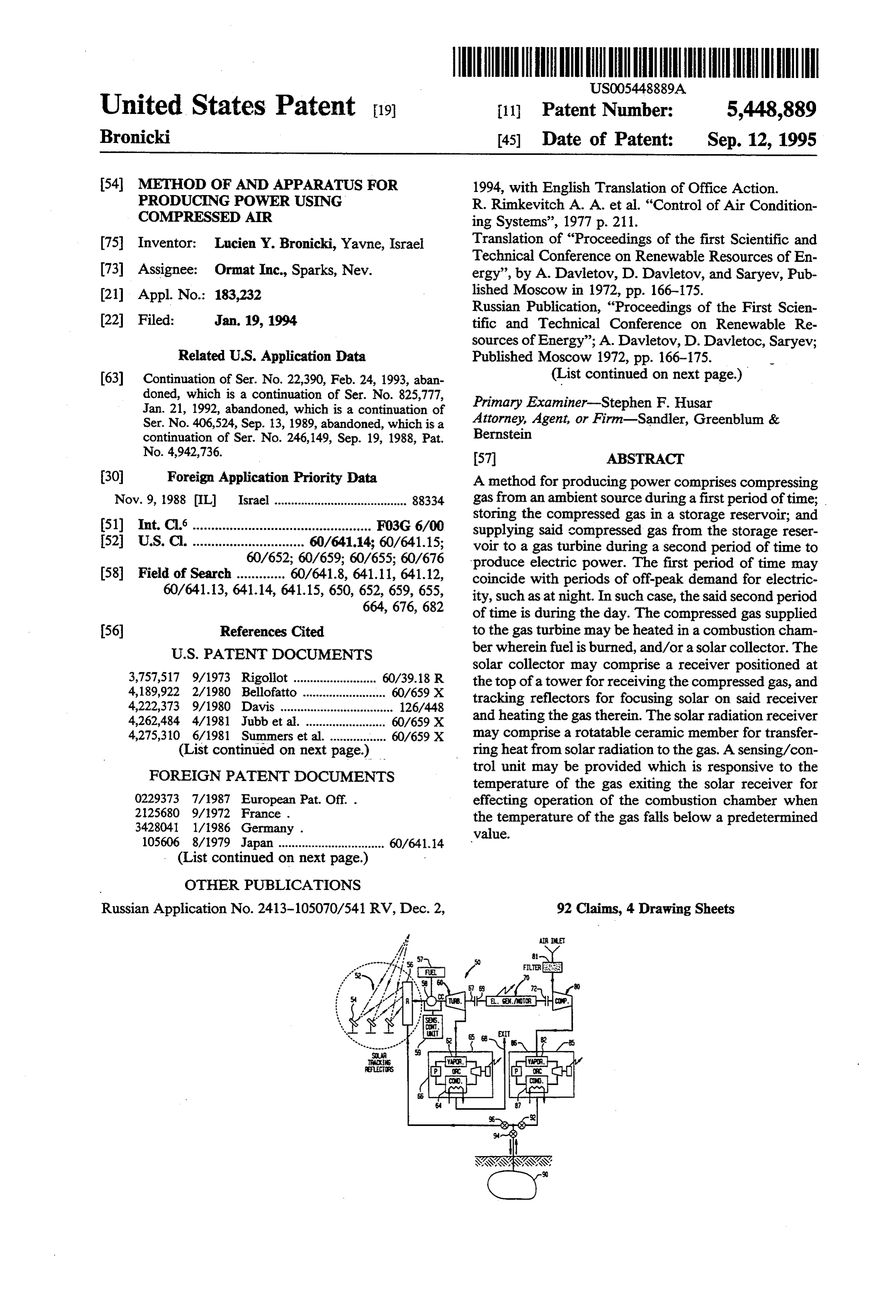
United States Patent 19 11 Patent Number: 5,448,889 Bronicki 45 Date of Patent: Sep. 12, 1995 54 METHOD OF AND APPARATUS FOR 1994, with English Translation of Office Action. PRODUCING POWER USING R. Rimkevitch A. A. et al. "Control of Air Condition COMPRESSED AR ing Systems', 1977 p. 211.
75 Inventor: Lucien Y. Bronicki, Yavne, Israel Translation of "Proceedings of the first Scientific and Technical Conference on Renewable Resources of En 73) Assignee: Ormat Inc., Sparks, Nev. ergy', by A. Davletov, D. Davietov, and Saryev, Pub 21) Appl. No.: 183,232 lished Moscow in 1972, pp. 166-175. Russian Publication, "Proceedings of the First Scien 22 Filed: Jan. 19, 1994 tific and Technical Conference on Renewable Re sources of Energy”; A. Davletov, D. Davletoc, Saryev;
Related U.S. Application Data Published Moscow 1972, pp. 166-175.
63 Continuation of Ser. No. 22,390, Feb. 24, 1993, aban (List continued on next page.) doned, which is a continuation of Ser. No. 825,777, Primary Examiner-Stephen F. Husar Jan. 21, 1992, abandoned, which is a continuation of
Ser. No. 406,524, Sep. 13, 1989, abandoned, which is a Attorney, Agent, or Firn-Sandler, Greenblum & continuation of Ser. No. 246,149, Sep. 19, 1988, Pat. Bernstein
No. 4,942,736. 57 ABSTRACT 30 Foreign Application Priority Data A method for producing power comprises compressing Nov. 9, 1988 IL Israel ........................................ 88334 gas from an ambient source during a first period of time; storing the compressed gas in a storage reservoir; and 51) Int. Cl................................................ F03G 6/00 supplying said compressed gas from the storage reser 52 U.S.C. .............................. 60/641.14; 60/641.15; voir to a gas turbine during a second period of time to 60/652; 60/659; 60/655; 60/676 produce electric power. The first period of time may 58 Field of Search ............. 60/641.8, 641.11, 641.12, coincide with periods of off-peak demand for electric 60/641.13, 641.14, 641.15, 650, 652, 659, 655, ity, such as at night. In such case, the said second period 664, 676,682 of time is during the day. The compressed gas supplied 56) References Cited to the gas turbine may be heated in a combustion cham
solar collector may comprise a receiver positioned at 3,757,517 9/1973 Rigoliot ......................... 60/39.18 R the top of a towerfor receiving the compressed gas, and 4,189,922 2/1980 Bellofatto ......................... 60/659 X tracking reflectors for focusing solar on said receiver 4,222,373 9/1980 Davis ........... ... 126/448 4,262,484 4/1981 Jubb et al. ....... . 60/659 X and heating the gas therein. The solar radiation receiver 4,275,310 6/1981 Summers et al. ................. 60/659 X may comprise a rotatable ceramic member for transfer (List continued on next page.) ring heat from solar radiation to the gas. A sensing/con
FOREIGN PATENT DOCUMENTS
trol unit may be provided which is responsive to the temperature of the gas exiting the solar receiver for 0229373 7/1987 European Pat. Off. . effecting operation of the combustion chamber when 2125680 9/1972 France . the temperature of the gas falls below a predetermined 3428041 1/1986 Germany . value.
105606 8/1979 Japan ................................ 60/641-14
(List continued on next page.)
Russian Application No. 2413-105070/541 RV, Dec. 2, 92 Claims, 4 Drawing Sheets
Page 2
4,403,601 9/1983 Hunt .................................... 126/435 The Netherlands.
4,581,897 4/1986 Sankrithi. 60/64.15 X "Eighty Atmospheres in Reserve', EPRI Journal, Palo 4,630,436 12/1986 Frutschi........................... 60/39.183 Alto, Calif.-Apr. 1979.
4,765,142 8/1988 Nakhamkin ........................... 60/652 "CAEScope', Compressed Air Energy Storage News 4.942,736 7/1990 Bronicki ........................... 60/655 X
FOREIGN PATENT DOCUMENTS Hans-Christoph Herbst et al., “Huntorf 290 MW-The 148907 li/1980 Japan ..................................... 60/655 World's first Air Storage System Energy Transfer (As 7614124 6/1978 Netherlands . set) Plant: Construction and Commissioning', Ameri 2006878 5/1979 United Kingdom . can Power Conference, Chicago, Ill.-Apr. 24-26, 1978. 8102443 9/1981 WIPO . R. Ruzich et al., "Soyland-The First U.S. Air Storage Energy Transfer (Asset) Plant', Prepared for and Ac
OTHER PUBLICATIONS cepted by the American Power Conference, Chicago, D. Weiner et al.; “Use of the Brayton Cycle in Solar Ill.-Apr. 18-20, 1983.
Electric Power Generation', Presented at the Gas Tur "Compressed-Air Energy Storage: An Analysis of Fuel bine and Aeroengine Congress and Exposition-Jun. Flexibility and Plant Components”, BBC Brown Bo 4-6, 1989-Toronto, Canada. veri, Inc., AP-5122-Research Project 1791-8, Final R. Schainker; "Compression-Air Energy Storage Report, May 1987.
Compressed Air Magazine, Jul., 1978, Compressed Air
(CAES): Overview, Performance, and Cost Data for Storage-A Peak-Shaving Concept for Electrical Utili 25MW to 220 MW Plants', IEEE Transactions on ties.
Power Apparatus and Systems, vol. PAS-104, No. 4, Copy of a translation of an action from U.S.S.R. State Apr. 1985. for Inventions and Discoveries issued around Jun. 1990. R. Bons et al., "Predicting the Behavior of Solar Dy Brown Boveri Review, vol. 67, No. 12, Dec. 1980, pp. namic Closed Brayton Cycle Power Conversions Sys 723-733, entitled: “Air-Storage Power plants with spe tems', Presented at the Gas Turbine and Aeroengine cial considerations of USA conditions'.
Page 3
Drawing sheet — no readable text.
Page 4
Drawing sheet — no readable text.
Page 5
Drawing sheet — no readable text.
Page 6
Drawing sheet — no readable text.
Page 7
from an ambient source during a first period of time;
METHOD OF AND APPARATUS FOR storing the compressed gas in a storage reservoir; and PRODUCING POWER USING COMPRESSED AR supplying said compressed gas from the storage reser voir to a gas turbine during a second period of time to
This application is a continuation of application Ser. 5 produce electric power. The first period of time may No. 08/022,390 filed Feb. 24, 1993, now abandoned, coincide with periods of off-peak demand for electric which is a continuation of application Ser. No. ity, such as at night. In such case, the said second period 07/825,777 filed Jan. 21, 1992, now abandoned, which is of time is during the day.
a continuation of application Ser. No. 07/406,524 filed The compressed gas supplied to the gas turbine may Sep. 13, 1989 now abandoned, which is a continuation 10 be heated in a combustion chamber wherein fuel is of application Ser. No. 07/246,149 filed Sep. 19, 1988, burned, and/or a solar collector. The solar collector. which issued as U.S. Pat. No. 4,942,736 on Jul. 24, 1990. may comprise a receiver positioned at the top of a tower TECHNICAL FIELD for receiving the compressed gas, and tracking reflec This invention relates to producing power using com 15 tors for focusing solar radiation on said receiver and heating the gas therein. The solar radiation receiver pressed air and more particularly is concerned with a may comprise method of and apparatus for producing power from ring heat fromasolar rotatable ceramic member for transfer radiation to the gas.
compressed air using solar energy and a gas turbine. A sensing/control unit may be provided which is BACKGROUND OF THE INVENTION responsive to the temperature of the gas exiting the solar
In recent years, domestic, commercial and industrial chamber receiver for effecting operation of the combustion power consumption in many countries, particularly predetermined when the temperature of the gas falls below a during the hours of peak power consumption, has been value.
growing at a seemingly ever increasing rate. Because Existing caverns, such as artificial salt caverns and electric power utility companies are obligated to furnish 25 underground aquifers can be used as storage reservoirs for storing the compressed gas. Underground caverns power at levels sufficient to meet any customer require located in geological fields where oil wells exist, also ment even if such levels occur infrequently or for only can be used as storage reservoirs with existing oil wells a few hours a day, the generating power capacity of the electric utility companies must be larger than the aver and reservoirs such as dry and old ones etc., i.e., also the age power level requirements in order to provide the 30 drilling itself reaching the reservoirs being preferably incremental power needed for periods of peak demand. utilized in the present invention. By utilizing existing Normally, and particularly in many countries in the dry oil wells as the subsystem used in storing the com summer time, peak power consumption occurs during pressed air necessary in operation of the gas turbine, in several hours in the daytime, consumption levels falling accordance with the present invention, considerable to their so-called "off peak' levels during the night. 35 savings in construction costs are made, with the use of Electric utility companies conventionally operate available solar energy to heat the compressed gas sup generating plants having minimal costs and reasonably plied to the gas turbine further cutting costs wherein the low operating costs, for example coal burning plants, to gas used in the gas turbine is compressed during period supply the base load and intermediate load of customers of relatively cheap off-peak electricity. connected to the electric grid. Because peak power In the present invention, an electric motor is used to demands on electric utility companies occur only for operate the compressors and the motor can be coupled, relatively short periods of time, more expensive operat selectively, to the turbine and operates as an electric ing plants, such as gas turbines, which can be brought generator. In a preferred embodiment, the compressor onto line quickly to furnish power are used during the is a multi-stage compressor and the gas turbine is a short periods of peak demand. Consequently, the cost of 45 multi-stage turbine. Furthermore, heat generated dur peak power is normally several times larger than the ing the compression of the gas and contained therein is cost of what is called baseload or "off-peak' power. transferred to another fluid in a heat exchanger which Recently, a system has been developed for providing can be part of a waste heat converter for producing peak power using a gas turbine wherein air necessary electrical power, the waste heat converter, preferably for the operation of the gas turbine is stored in under SO being an organic-fluid Rankine cycle power plant. ground caverns. At night, when relatively inexpensive BREF DESCRIPTION OF THE ORAWINGS power is available, an electrically driven air compressor is operated for compressing the air. During the day, Embodiments of the invention are described below when peak power is required, the compressed air is by way of example, and with reference to the accompa released from the caverns to the gas turbine for produc 55 nying drawings wherein:
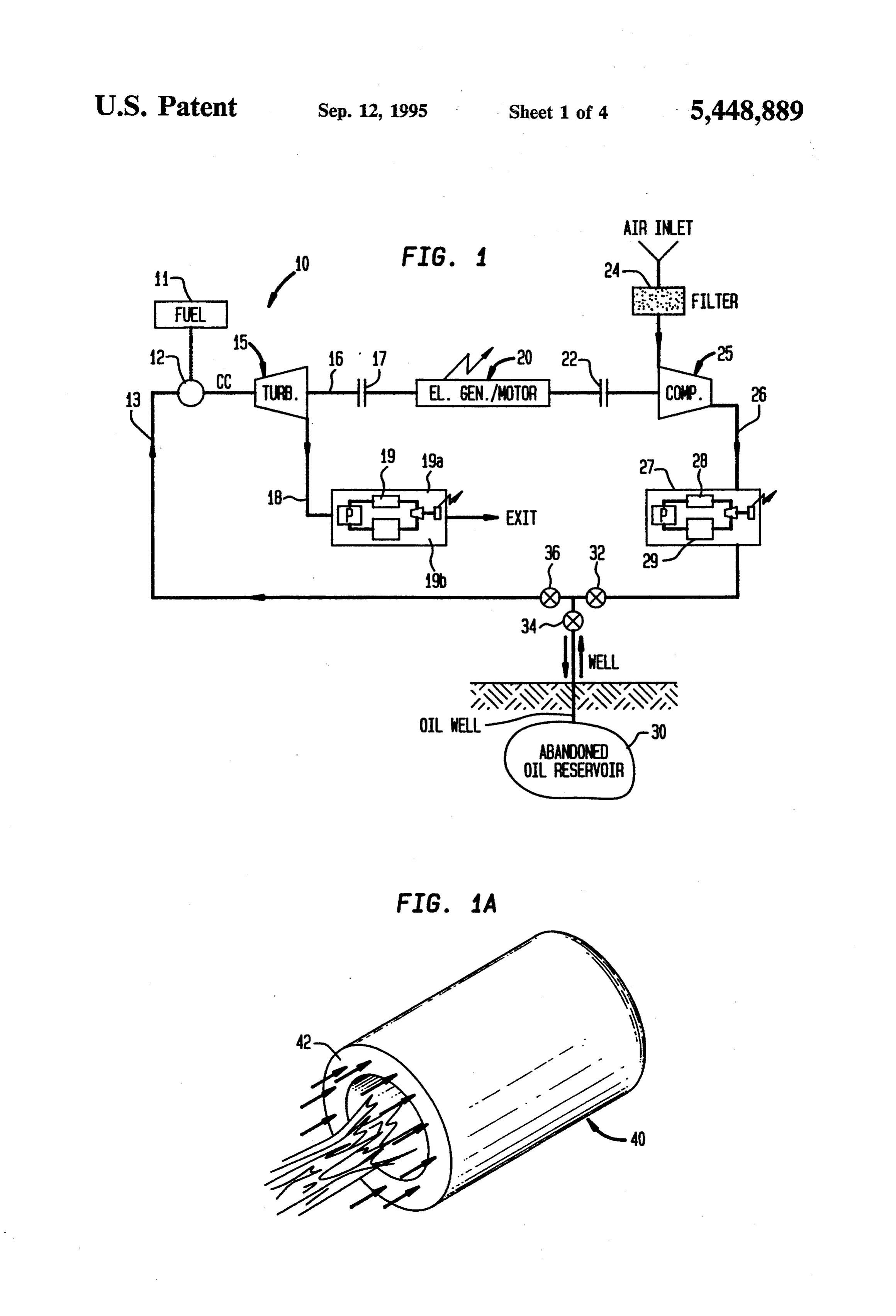
ing power via a coupled generator. In such a system, FIG. 1 is a block diagram of one embodiment of expensive caverns conventionally constructed under apparatus for producing power in accordance with the ground are required to store the compressed gas. present invention;
It is therefore an object of the present invention to FIG. 1A shows a schematic diagram of the preferred provide a new and improved method of and apparatus embodiment of a combustion chamber of the present for producing electrical power during periods of peak invention;
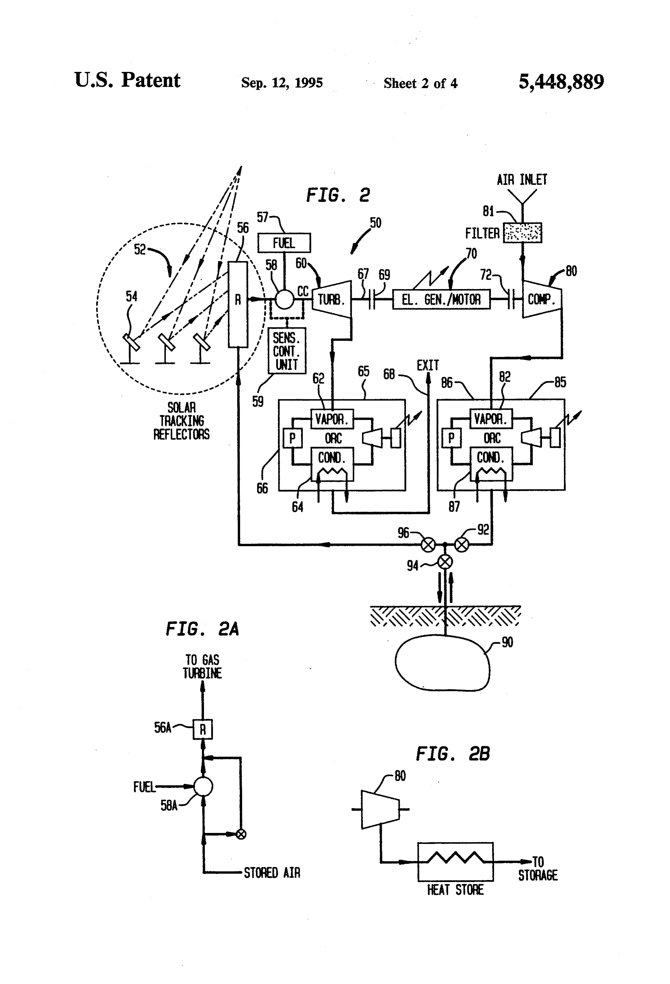
power demand wherein the disadvantages as outlined FIG. 2 is a block diagram of another embodiment of including and related to the relatively large costs are apparatus for producing power in accordance with the reduced or substantially overcome. present invention;
SUMMARY OF THE INVENTION
65 FIGS. 2A and 2B show modifications of certain com ponents of the apparatus shown in FIG. 2;
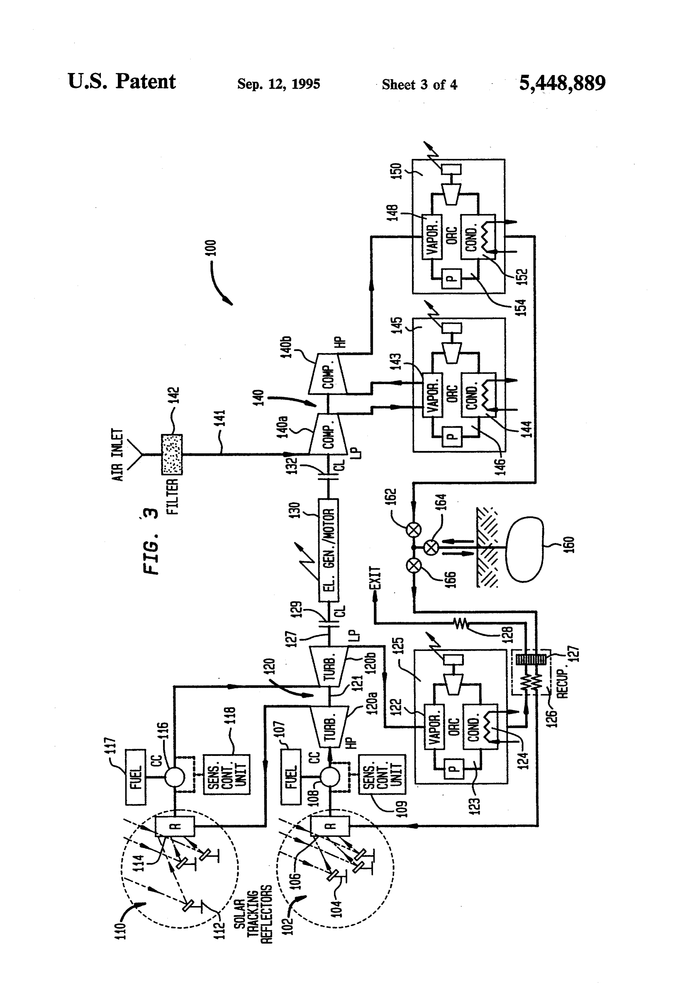
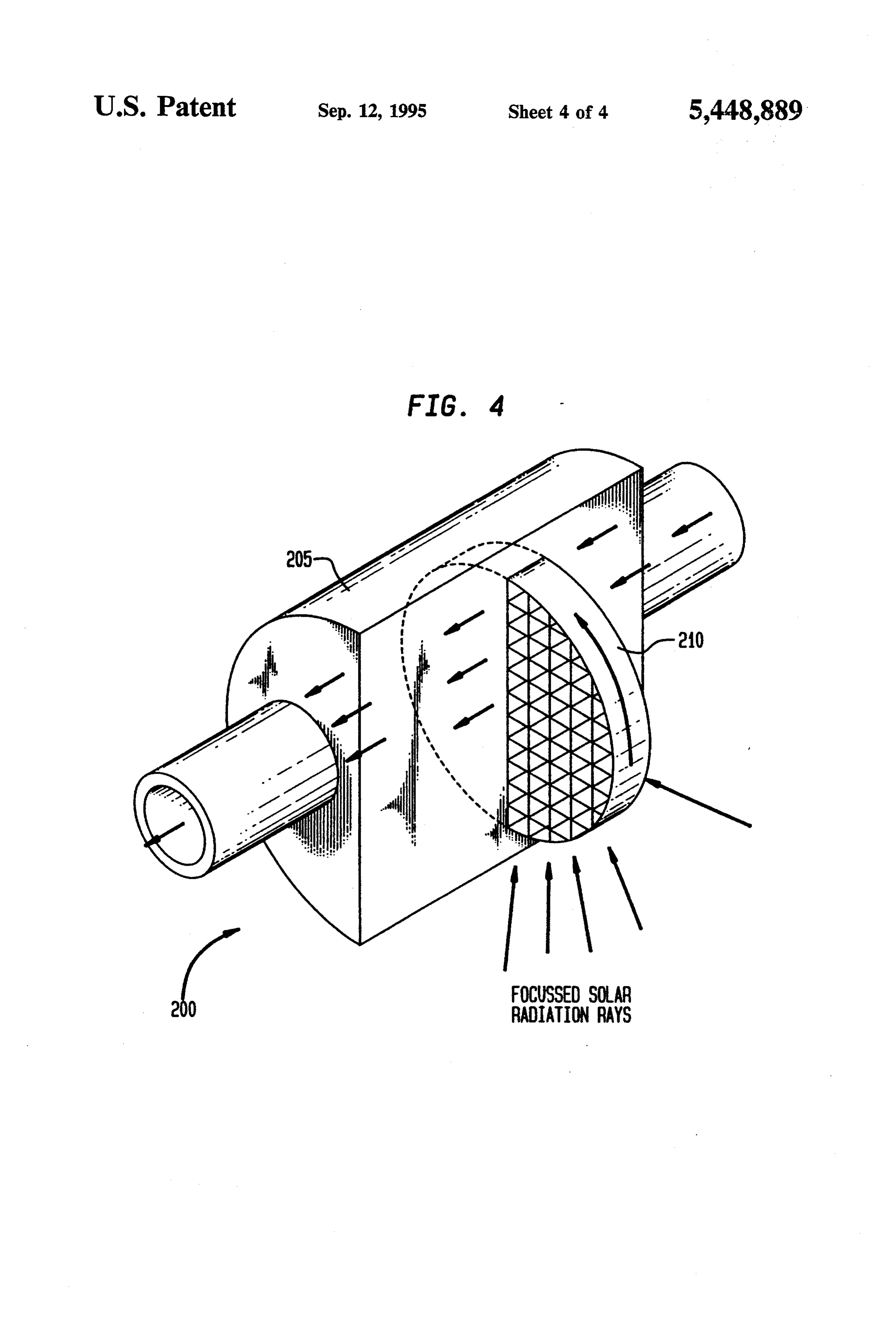
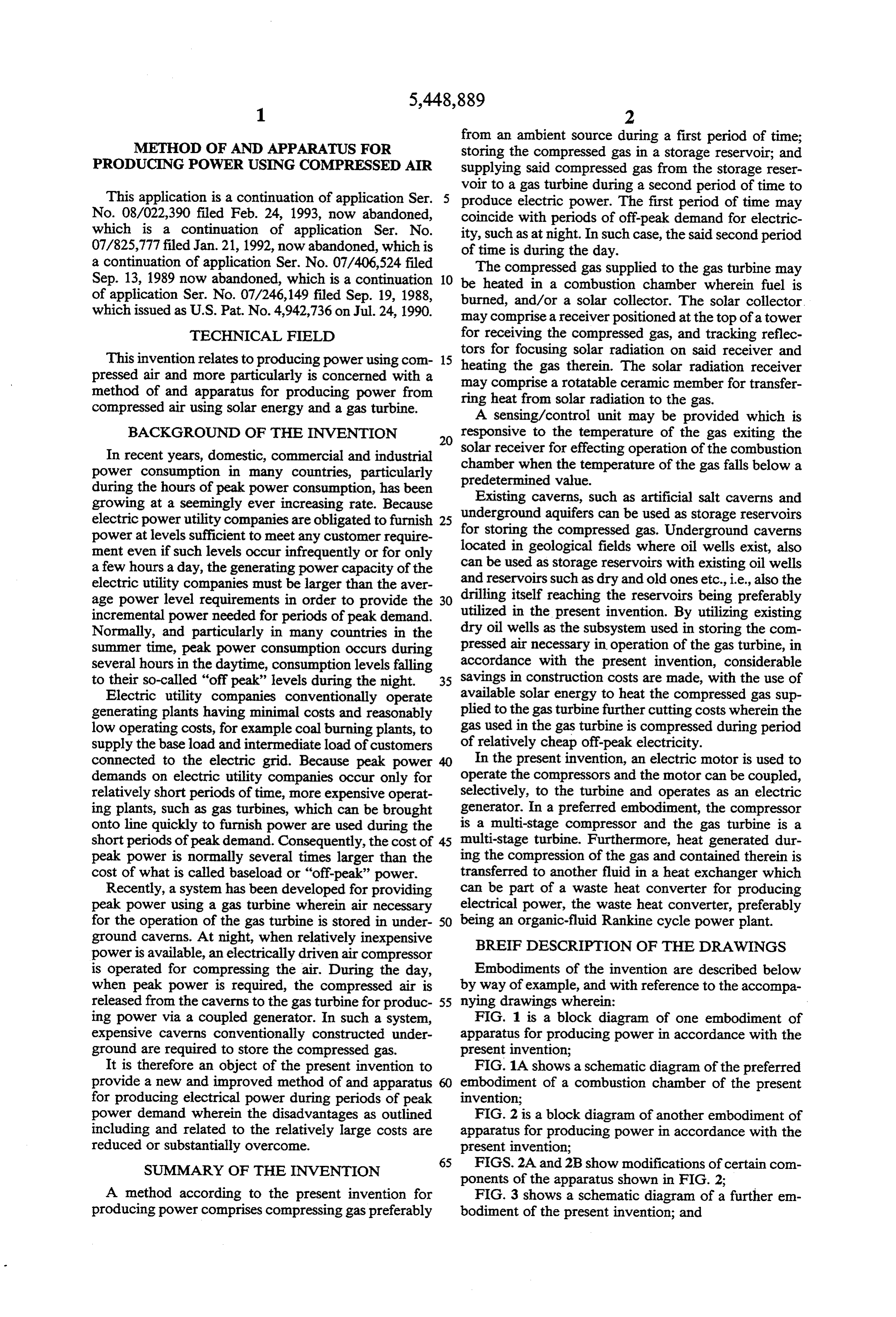
A method according to the present invention for FIG. 3 shows a schematic diagram of a further em producing power comprises compressing gas preferably bodiment of the present invention; and
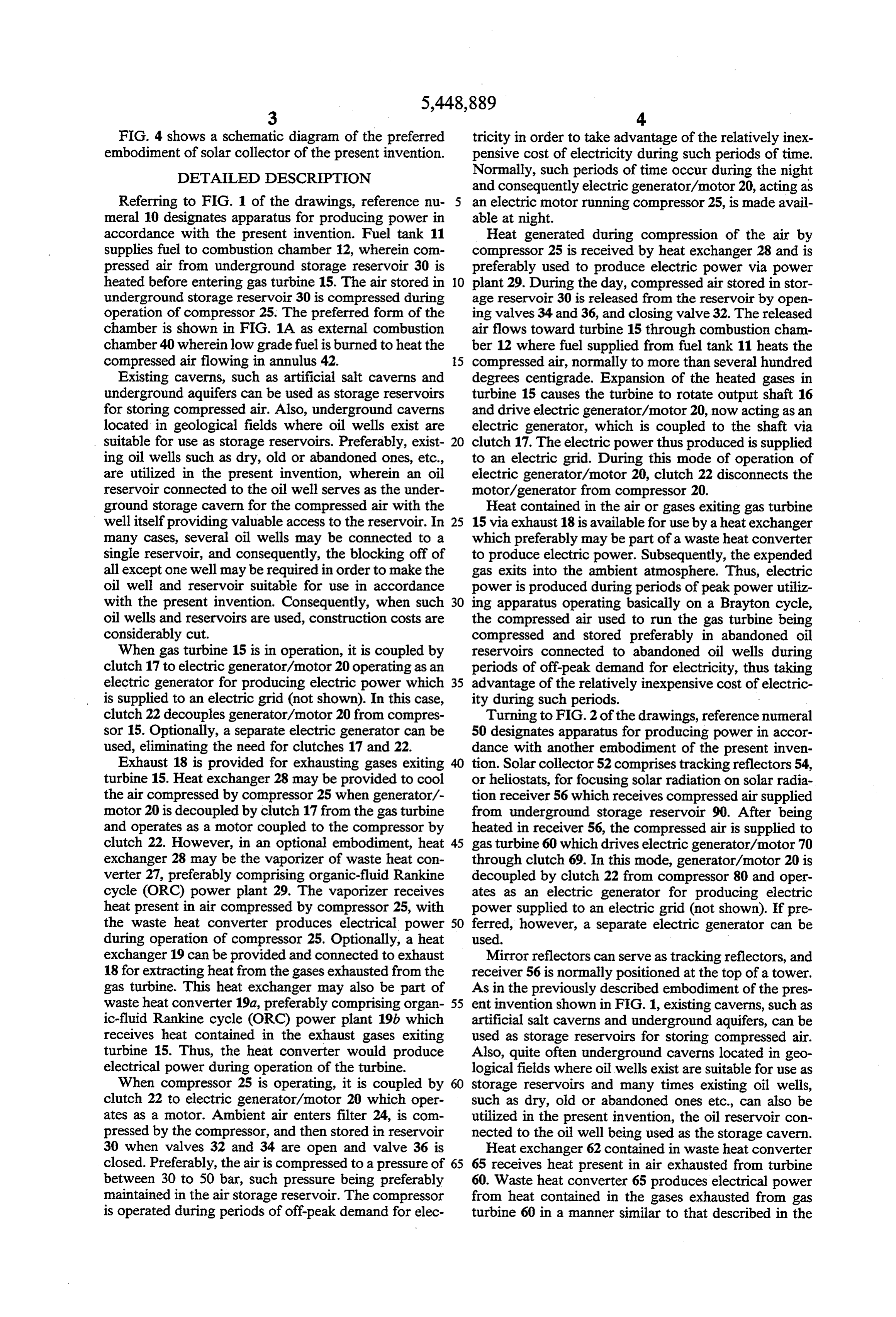
Page 8
FIG. 4 shows a schematic diagram of the preferred tricity in order to take advantage of the relatively inex embodiment of solar collector of the present invention. pensive cost of electricity during such periods of time. DETALED DESCRIPTION Normally, such periods of time occur during the night and consequently electric generator/motor 20, acting as
Referring to FIG. 1 of the drawings, reference nu an electric motor running compressor 25, is made avail meral 10 designates apparatus for producing power in able at night.
accordance with the present invention. Fuel tank 11 Heat generated during compression of the air by supplies fuel to combustion chamber 12, wherein com compressor 25 is received by heat exchanger 28 and is pressed air from underground storage reservoir 30 is preferably used to produce electric power via power heated before entering gas turbine 15. The air stored in 10 plant 29. During the day, compressed air stored in stor underground storage reservoir 30 is compressed during age reservoir 30 is released from the reservoir by open operation of compressor 25. The preferred form of the ing valves 34 and 36, and closing valve 32. The released chamber is shown in FIG. 1A as external combustion air flows toward turbine 15through combustion cham chamber 40 wherein low grade fuel is burned to heat the ber 12 where fuel supplied from fuel tank 11 heats the compressed air flowing in annulus 42. 15 compressed air, normally to more than several hundred Existing caverns, such as artificial salt caverns and degrees centigrade. Expansion of the heated gases in underground aquifers can be used as storage reservoirs turbine 15 causes the turbine to rotate output shaft 16 for storing compressed air. Also, underground caverns and drive electric generator/motor 20, now acting as an located in geological fields where oil wells exist are electric generator, which is coupled to the shaft via suitable for use as storage reservoirs. Preferably, exist 20 clutch 17. The electric power thus produced is supplied ing oil wells such as dry, old or abandoned ones, etc., to an electric grid. During this mode of operation of are utilized in the present invention, wherein an oil electric generator/motor 20, clutch 22 disconnects the reservoir connected to the oil well serves as the under motor/generator from compressor 20. ground storage cavern for the compressed air with the Heat contained in the air or gases exiting gas turbine well itself providing valuable access to the reservoir. In 25 15 via exhaust 18 is available for use by a heat exchanger many cases, several oil wells may be connected to a which preferably may be part of a waste heat converter single reservoir, and consequently, the blocking off of to produce electric power. Subsequently, the expended all except one well may be required in order to make the gas exits into the ambient atmosphere. Thus, electric oil well and reservoir suitable for use in accordance power is produced during periods of peak power utiliz with the present invention. Consequently, when such 30 ing apparatus operating basically on a Brayton cycle, oil wells and reservoirs are used, construction costs are the compressed air used to run the gas turbine being considerably cut. compressed and stored preferably in abandoned oil When gas turbine 15 is in operation, it is coupled by reservoirs connected to abandoned oil wells during clutch 17 to electric generator/motor 20 operating as an periods of off-peak demand for electricity, thus taking electric generator for producing electric power which 35 advantage of the relatively inexpensive cost of electric is supplied to an electric grid (not shown). In this case, ity during such periods.
clutch 22 decouples generator/motor 20 from compres Turning to FIG.2 of the drawings, reference numeral sor 15. Optionally, a separate electric generator can be 50 designates apparatus for producing power in accor used, eliminating the need for clutches 17 and 22. dance with another embodiment of the present inven Exhaust 18 is provided for exhausting gases exiting tion. Solar collector 52 comprises tracking reflectors 54, turbine 15. Heat exchanger 28 may be provided to cool or heliostats, for focusing solar radiation on solar radia the air compressed by compressor 25 when generator/- tion receiver 56 which receives compressed air supplied motor 20 is decoupled by clutch 17 from the gas turbine from underground storage reservoir 90. After being and operates as a motor coupled to the compressor by heated in receiver 56, the compressed air is supplied to clutch 22. However, in an optional embodiment, heat 45 gas turbine 60 which drives electric generator/motor 70 exchanger 28 may be the vaporizer of waste heat con through clutch 69. In this mode, generator/motor 20 is verter 27, preferably comprising organic-fluid Rankine decoupled by clutch 22 from compressor 80 and oper cycle (ORC) power plant 29. The vaporizer receives ates as an electric generator for producing electric heat present in air compressed by compressor 25, with power supplied to an electric grid (not shown). If pre the waste heat converter produces electrical power 50 ferred, however, a separate electric generator can be during operation of compressor 25. Optionally, a heat used.
exchanger 19 can be provided and connected to exhaust Mirror reflectors can serve as tracking reflectors, and 18 for extracting heat from the gases exhausted from the receiver 56 is normally positioned at the top of a tower. gas turbine. This heat exchanger may also be part of As in the previously described embodiment of the pres waste heat converter 19a, preferably comprising organ 55 ent invention shown in FIG. 1, existing caverns, such as ic-fluid Rankine cycle (ORC) power plant 19b which artificial salt caverns and underground aquifers, can be receives heat contained in the exhaust gases exiting used as storage reservoirs for storing compressed air. turbine 15. Thus, the heat converter would produce Also, quite often underground caverns located in geo electrical power during operation of the turbine. logical fields where oil wells exist are suitable for use as When compressor 25 is operating, it is coupled by storage reservoirs and many times existing oil wells, clutch 22 to electric generator/motor 20 which oper such as dry, old or abandoned ones etc., can also be ates as a motor. Ambient air enters filter 24, is com utilized in the present invention, the oil reservoir con pressed by the compressor, and then stored in reservoir nected to the oil well being used as the storage cavern. 30 when valves 32 and 34 are open and valve 36 is Heat exchanger 62 contained in waste heat converter closed. Preferably, the air is compressed to a pressure of 65 65 receives heat present in air exhausted from turbine between 30 to 50 bar, such pressure being preferably 60. Waste heat converter 65 produces electrical power maintained in the air storage reservoir. The compressor from heat contained in the gases exhausted from gas is operated during periods of off-peak demand for elec turbine 60 in a manner similar to that described in the
Page 9
embodiment shown in FIG. 1. Preferably, waste heat tainer 205 within which the compressed air flows in an converter 65 comprises organic-fluid Rankine cycle axial direction, and member 210 rotatable relative to the (ORC) power plant 66 containing vaporizer heat ex container. A portion of member 210 extends external to changer 62 and condenser 64 cooled by cooling water. the sealed container, and is located at the focus of the Heat received in heat exchanger 62 vaporizes the work tracking reflectors for receiving the focused solar radia ing fluid of the power plant, the vaporized working tion. Rotation of member 210 moves the heated portion fluid being furnished to a turbine for producing electric of member 210 internal to the sealed container where power. Subsequently, the expended air exits via exhaust heat stored in such portion is transferred to the com conduit 68. pressed air in the container. Thus, rotation of member Combustion chamber 58, run on fuel supplied from O 210 alternately subjects the member to focused heat, fuel supply 57 and located between receiver 56 and which is absorbed by the member, and to the flowing turbine 60, is provided for maintaining a preselected compressed air to which heat from the member is trans temperature of the air entering the gas turbine. Prefera ferred.
bly, the operation of combustion chamber 58 is con In the preferred construction of member 210, ceramic trolled by sensing/control unit 59 which senses the 15 material is used and the member has a matrix form. temperature of the air exiting receiver 56. When the Also, the seals by which the rotatable member is sealed temperature of the air exiting solar receiver 56 is suffi during its rotation are preferably cooled by gas or air cient, the air can flow directly to turbine 60 via suitable this flow. - conduits, bypassing the combustion chamber. When In operation of the embodiment of FIG. 2, compres unit 59 senses that the air exiting receiver 56 is below a sor 80, driven by electric generator/motor 70 operated preselected value, unit 59 directs the air, by way of as a motor and coupled by clutch 72 to the compressor, suitably arranged valves and piping, into the combus compresses air supplied through filter 41. The com tion chamber and initiates operation of the combustion pressed air is stored in reservoir 90 when valves 92 and chamber by causing fuel to be burned therein at a rate 94 are open and valve 96 is closed. Preferably, the air is that maintains the temperature of the air entering the 25 compressed to a pressure of between 30 to 50 bar; and gas turbine at its design value. Preferably, combustion such a pressure is also maintained in the air storage chamber 58 is an external combustion chamber that uses reservoir.
low grade fuel to heat the air as shown in FIG. 1A. In The compressor is operated during periods of off order to ensure high combustion efficiency, the com peak demand for electricity in order to take advantage bustion chamber may be located before receiver 56 as 30 of the relatively inexpensive cost of electricity during shown in FIG. 2A. such periods of time. Normally, such periods of time When clutch 72 is activated, clutch 69 is deactivated, occur during the night and consequently electric and generator/motor 70 is operated as a motor, com generator/motor 70 is made available for use, acting as pressor 80 is driven by the motor and compresses ambi an electric motor running compressor 80. ent air supplied through filter 81. If preferred, a separate 35 Heat generated during compression and present in electric motor can be used to drive the compressor. the compressed air is received by heat exchanger 82 and Similar to the previously described embodiment, heat used to produce electric power via power plant 86. present in the air compressed by compressor 80 is ex Alternatively, such heat can be stored in a heat sink for tracted by heat exchanger 82 contained in waste heat use at a later time.
converter 85 which extracts heat present in air com In power plant 86, the heated air passes through heat pressed by compressor 80. The heat extracted from the exchanger 82 vaporizing an organic-working fluid, such compressed air by the waste heat converter during the as Freon or the like, the vapors being supplied to a operation of the compressor is utilized by the converter turbine contained in power plant 86 for driving a gener to generate electricity. Preferably, waste heat converter ator and producing electric power. Vapors exhausted 85 comprises organic-fluid Rankine cycle (ORC) power 45 from this turbine are condensed in condenser 87 which plant 86 containing vaporizer heat exchanger 82, and is cooled by cooling water. A feed pump returns the condenser 84 cooled by cooling water. The heat re condensed organic-fluid to vaporizer heat exchanger ceived by heat exchanger 82 vaporizes the working 82.
fluid of the power plant, and the resultant vapors are During the day, the compressed air stored in storage supplied to a turbine in the power plant which drives a 50 reservoir 90 is made available by opening valves 94 and generator for producing electrical power. The ex 96 and closing valve 92. The compressed air flows pended vapors from the turbine are condensed by con toward turbine 60 through solar radiation receiver 56 denser 87 and returned to vaporizer 82. Alternatively, where focused solar radiation reaching receiver 56 from the heat extracted from the compressed air can be tracking reflectors 54 heats the compressed air normally stored in a heat store for use at a later time as indicated 55 to more than several hundred degrees centigrade. The in FIG.2B. Examples of suitable heat stores are: a water air that exits receiver 56 may have a temperature as high reservoir, and the heat storage layer of a salt water solar as 800 C. However, higher temperature can be ob pond. tained if required. Subsequently, the heated, com In the present embodiment, solar receiver 56 may pressed air may flow through combustion chamber 58 comprise a sealed container having pipes connected to to gas turbine 60 where expansion takes place. Alterna the reservoir of compressed air and positioned at the tively, the combustion chamber can be located up focus of the tracking reflectors for receiving focused stream of the solar receiver. Regardless of the location solar radiation which serves to heat the compressed air of the combustion chamber relative to the solar re flowing through the pipes. The temperature in the pipes ceiver, only the air or gases currently being supplied to may reach 1000 C., and the pressure may reach 50 bar 65 the turbine is heated by the burning fuel and solar radia or even higher. tion.
The preferred form of the solar receiver is shown in Expansion of the heated gases in turbine 60 causes the FIG. 4 as receiver 200 which comprises sealed con turbine to rotate shaft 67 driving electric generator/mo
Page 10
tor 70, now acting as an electric generator, and coupled pressure stage turbine 120b. Multi-stage compressor thereto via clutch 69 producing electric power supplied 140, which comprises low pressure stage compressor to an electric grid. During this mode of operation, 140a and high pressure compressor 140b, is driven by clutch 72 disconnects electric generator/motor 70 from electric generator/motor 130 when the latter operates compressor 80. as an electric motor. If preferred, however, a separate The temperature of the air exiting solar receiver 56 electric motor can be provided to drive compressor 140. may drop below a preselected value due to, for exam Solar collector 110 comprises tracking reflectors 112, ple, the presence of cloud cover that reduces the or heliostats, for focusing solar radiation, and solar amount of focused radiation reaching the receiver. In radiation receiver 114 for receiving focused solar radia such case, sensing/control unit 59 senses the tempera O tion. Collector 110 provides interstage reheating of the ture drop of the air and brings combustion chamber 58 air or gas exiting high pressure stage turbine 120a. The into operation in order to heat the air to maintain its reheated air is supplied to combustion chamber 116, temperature entering turbine 60. Heat remaining in the which is operated by sensing/control unit 118. When air or gases exiting gas turbine 60 is received by heat necessary, fuel from fuel tank 117 is supplied to cham exchanger 62 and used to produce electric power via 15 ber 116 to maintain the temperature of the gases or air power plant 66 in a manner similar to that which takes entering low pressure stage turbine 120b. In this man place in power plant 86 described above. Subsequently, ner, the efficiency of gas turbine 120 is improved. the expended gas exits via conduit 68. Mirror reflectors can be used as tracking reflectors As described above, solar energy is utilized to pro and receiver 114 is normally positioned at the top of a duce electric power using a gas turbine. Compressed air 20 tower. Air or gases exiting receiver 114 flow through used to run the gas turbine is compressed and stored combustion chamber 116 to low pressure stage gas tur during periods of off-peak demand for electricity, thus bine 120b. Alternatively, gases can flow directly to taking advantage of the relatively inexpensive cost of turbines 120a and 120b from solar receivers 106 and 114 electricity during such periods. Furthermore, quite via suitable conduits, bypassing combustion chambers often the periods of time during which electric power is 25 108 and 116 when the temperature of the air or gas is produced by the gas turbine will coincide with periods sufficient. Optionally, the gases can be diverted so as to of peak electric power demand. also flow through the combustion chambers by suitable Referring now to FIG. 3, reference numeral 100 des piping and valve arrangements when the combustion ignates a further embodiment of the present invention chambers are brought into operation. Combustion for producing power from solar energy. This embodi 30 chambers 108 and 116 are preferably external combus ment is similar to the embodiment shown in FIG. 2 tion chambers burning low grade fuel as shown in FIG. except that gas turbine 120 and compressor 140 are 1A. Optionally, the chambers may be positioned up multi-staged units. Second solar collector 110 and fur stream of receivers 106 and 114 instead of downstream ther waste heat converter 145 are provided between the to ensure high combustion efficiency. stages of the turbine and compressor respectively in 35 Heat exchanger 122, which is part of waste heat con order to raise the efficiency of the power generating verter 125, utilizes heat contained in air or gases exiting apparatus. Also, recuperator heat exchanger 126 is pro low pressure stage turbine 120b for producing electrical vided for additional heating of the compressed air sup power. As shown in FIG. 3, waste heat converter 125 plied to gas turbine 120. While the gas turbine may have preferably is in the form of an organic-fluid Rankine a generating capacity of 25 MW or greater, the present cycle (ORC) power plant 123 which comprises heat embodiment is also suitable for smaller generating ca exchanger 122 that functions as a vaporizer for vaporiz pacities as well. ing the working fluid of the power plant. The vaporized Solar collector 102 comprises tracking reflectors 104, working fluid is supplied to a turbine contained in the or heliostats, for focusing solar radiation on solar radia power plant for producing electrical power. Expended tion receiver 106 that receives the focused solar radia 45 vapors exiting the turbine are condensed in condenser tion. Collector 102 heats compressed air drawn from 124 which is cooled by cooling water. reservoir 160. The air in reservoir 160 had been com Recuperator heat exchanger 126 is provided for uti pressed by compressor 140 during the previous night lizing residual heat remaining in air or gases leaving time operation of multi-stage compressor 140. During power plant 123 to preheat the compressed air supplied the next day, compressed air from reservoir 160 is sup 50 from storage reservoir 160 to solar receiver 106. Prefer plied to multi-stage gas turbine 120 which drives elec ably, recuperator 126 comprises rotatable ceramic tric generator/motor 130, operating as an electric gen member 127 that is alternately heated by the air or gases erator through activated clutch 129, clutch 132 being leaving power plant 123, and cooled by the compressed deactivated at this time. Generator/motor 130 thus air or gases drawn from reservoir 160. In this manner, produces electric power which is supplied to an electric 55 the air or gases delivered to receiver 106 is preheated by grid (not shown). If preferred, however, a separate the exhaust gases as member 127 rotates. Exhaust con electric generator and motor can be used. duit 128 provides an exit for the expended air or gases to As in the embodiment of FIG. 2, mirror reflectors the ambient atmosphere.
can be used as tracking reflectors and receiver 106 is In the present embodiment, inter-stage heat ex normally positioned at the top of a tower. Combustion 60 changer 143, which is part of waste heat converter 145, chamber 108, which may be located between receiver preferably is in the form of organic-fluid Rankine cycle 106 and turbine 120, or upstream of the receiver, main power plant 146. This power plant comprises heat ex tains the desired temperature level of air entering the changer 143, which functions as a vaporizer, supplying the gas turbine. Fuel supplied from fuel supply 107 is vaporized working fluid to a turbine that produces burned in the combustion chamber, the supply of fuel 65 electrical power from heat contained in compressed air being controlled by sensing/control unit 109. exhausting from low pressure stage compressor 140a. In In the present embodiment, multi-stage gas turbine addition, waste heat converter 150, which includes heat 120 comprises high pressure stage turbine 120a and low exchanger 148 for receiving heat present in compressed
Page 11
9 O air exiting high pressure stage compressor 140b is pro tor, which produces electric power. During this opera vided for producing electric power therefrom. Waste tion, clutch 132 is activated, and generator/motor 130 is heat converter 150 preferably comprises an organic disconnected from compressor 140. If the temperature fluid Rankine cycle power plant 154. of the air or gases exiting either solar receivers 106 and Solar receivers 106 and 114 in the present embodi 114 drops below a preselected value, sensing/control ment, like receiver 56 in the embodiment of FIG. 2, may units 109 and 118 sense the temperature drop and brings comprise a sealed container having pipes positioned at either one of the other or both of combustion chambers the focus of the tracking reflectors for receiving fo 108 and 116 into operation for maintaining the tempera cused solar radiation. The compressed air or gases flow ture of gases or air entering turbines 120a and 120b. through these pipes and is heated. Operating tempera 10 Gases exiting low pressure stage turbine 120b flow to ture in the pipes may reach 1000 deg. C., and operating heat exchanger 122 of organic-fluid Rankine Cycle pressure on the pipes may be 50 bar or even higher. power plan 123 where heat contained therein is used to However, operating temperatures and pressures of gases or air in receiver 114, positioned between the vaporize
Freon the working fluid of this power plant, such as etc., the vapors being supplied to the power plant stages of the gas turbine 120 could be lower than these. 5 turbine to produce
Preferably, solar receivers 106 and 114 comprise a tor. Vapors excitingelectric power by driving a genera rotatable member, a portion of which is positioned ex densed in condenser 124 cooledplant the power turbine are con ternal to a sealed container at the focus of the tracking feed pump returns the condensed organic-fluidwater. by cooling
heat reflectors and is heated by the focused solar radiation. exchanger 122. Further heat contained in gases or air Another portion of the member is positioned internal to 20 exiting power plant 123 is used in recuperator 126 to the sealed container and transfers heat to the com heat compressed pressed air or gases flowing past this portion in the receiver 106. Expended air flowing from air reservoir 160 to manner shown in FIG. 4. As before, the member is gases are exhausted from appa preferably constructed from ceramic material a matrix ratus The 100 via exhaust conduit 128.
advantages and improved results furnished by form. Finally, the seals of the container are preferably the method
and apparatus of the present invention are cooled by gas or air flow. apparent from the foregoing description of the embodi When compressors 14.0a and 140b are driven by elec tric generator/motor 130 operating as a motor and ments of the invention. Various changes and modifica clutch 132 is activated, the compressors compress the tions may be made without departing from the spirit and air to a pressure of between 30 to 50 bar before it is 30 the scope of the invention as described in the claims that follow.
delivered to the reservoir. The compressed air is stored I claim:
at similar pressure in reservoir 160 when valves 162 and 1. A method for producing power comprising the 164 are open. In a manner similar to the previous em bodiment, the compressors are operated during the steps of compressing gas from an ambient source dur periods of off-peak demand for electricity to take ad 35 ing a first period of time; storing the compressed gas in vantage of relatively inexpensive electricity during such a storage reservoir; and supplying said compressed gas periods of time. Normally, such periods of time occur from the storage reservoir to a gas turbine during a during the night. second period of time to produce electric power Heat generated during compression of the air by the wherein the compressed gas is supplied to the gas tur compressors is received by heat exchangers 143 and 148 bine through a solar collector interposed between the and is used to produce electric power using power reservoir and the turbine for heating the compressed plants 146 and 154 in a manner analogous to the manner gaS.
of operation of power plants 66 and 86 contained in the 2. The method according to claim 1 wherein the previous embodiment shown in FIG. 2. During the day, compressed gas supplied to the gas turbine is heated in stored compressed air is made available from storage 45 a combustion chamber wherein fuel is burned. reservoir 160 by opening valves 166 and 164, and clos 3. The method according to claim 2 wherein said ing valve 162. The compressed air flows into multi solar collector comprises a receiver positioned at the stage turbine 120 through recuperator heat exchanger top of a tower for receiving the compressed gas, and 126 and through solar radiation receiver 106 where tracking reflectors for focusing solar radiation on said focused solar radiation reaching receiver 106 from 50 receiver for heating the gas therein. tracking reflectors 104 heats the compressed air. Nor 4. The method according to claim 3 further compris mally, the air is heated to more than several hundred ing the step of commencing operation of said combus degrees centigrade, the gases reaching a temperature as tion chamber in response to sensing a fall in temperature high as 800 deg. C. If necessary, however, also in the of the gas exiting the solar receiver below a predeter present embodiment, higher temperatures can be used. 55 mined value.
The heated compressed air flows from receiver 106 5. A method for producing power comprising the through combustion chamber 108 reaching high pres steps of compressing gas from an ambient source dur sure stage turbine 120a where expansion takes place. ing a first period of time; storing the compressed gas in Expanded gases exhausted from turbine 120a flow a storage reservoir; supplying said compressed gas from through receiver 114 and combustion chamber 116 the storage reservoir to a gas turbine coupled to a gen where the gases are heated once again to relatively high erator during a second period of time to produce elec temperatures of several hundred degrees. Subsequently, tric power; and cooling the compressed gas prior to the heated gases are supplied to low pressure stage storing it by transferring heat present in the compressed turbine 120b where expansion occurs once again. Ex gas to another fluid in a heat exchanger; and further pansion of the gases in turbines 120a and 120b cause the 65 comprising producing electric power using heat trans turbines to drive shaft 121 and shaft 127 respectively. ferred to the other fluid in said heat exchanger, said heat These shafts are coupled by clutch 129 to electric exchanger being part of a waste heat converter separate generator/motor 130, now acting as an electric genera from said generator.
Page 12
6. The method according to claim 5 wherein said heat 22. Apparatus according to claim 20 wherein said supplied to the other fluid vaporizes the fluid, the va storage reservoir is an abandoned oil reservoir and said pors being supplied to a turbine contained in said waste means for supplying compressed gas to said gas turbine heat converter to produce electric power, said waste include an abandoned oil well for supplying gas from heat converter being an organic-fluid Rankine cycle storage reservoir to the gas turbine through the re power plant. ceiver.
7. Apparatus for producing power using compressed 23. Apparatus according to claim 15 wherein said gas and a gas turbine comprising: compressor means for combustion chamber is an extenal combustion chamber compressing said gas; a storage reservoir for storing gas operating on low grade fuel.
compressed by said compressor means; means for sup O 24. Apparatus according to claim 20 wherein said plying compressed gas from said reservoir to the gas combustion chambers are external combustion chamber turbine; and a solar collector interposed between said operating on low grade fuel.
reservoir and said turbine for heating the gas supplied to 25. Apparatus according to claim 7 wherein said said turbine through said solar collector. 15 compressor means is a multi-stage compressor.
8. Apparatus according to claim 7 further comprising 26. Apparatus according to claim 7 wherein said gas a heat exchanger for cooling the air compressed by said 1S a.
compressor means before the air is stored in said storage 27. Apparatus according to claim 7 wherein said reservoir. means for heating the gas includes an external combus 9. Apparatus according to claim 7 further comprising 20 tion chamber operating on low grade fuel. a heat exchanger for cooling gases exiting said gas tur 28. Apparatus for producing power using compressed bine. gas and a gas turbine for driving an electric generator 10. Apparatus according to claim 7 including means comprising: compressor means for compressing said gas for operating said compressor means during a first per during a first period of time; a storage reservoir for iod of time which includes periods of offpeak demand 25 storing air compressed by said compressor means; for electricity. means for supplying compressed gas to the gas turbine 11. Apparatus according to claim 10 wherein said during a second period of time to produce power; first period of time is during the night. means for heating the gas supplied to said turbine; and 12. Apparatus according to claim 10 further compris further comprising a heat exchanger for cooling the gas ing an electric motor for driving said compressor. 30 compressed by said compressor means before the gas is 13. Apparatus according to claim 12 wherein said stored in said storage reservoir, wherein said heat ex electric motor operates as an electric generator when changer is part of a waste heat converter separate from driven by the gas turbine during the second period of said generator for producing electrical power. time.
29. Apparatus 14. Apparatus according to claim 7 wherein said solar 35 waste heat converter according to claim 28 wherein said collector comprises a receiver positioned at the top of a power plant and, saidisheat an organic-fluid Rankine Cycle exchanger is a vaporizer for tower for receiving the compressed gas, and tracking vaporizing reflectors for focusing solar on said receiver and heating fluid Rankine cycle power plant. fluid of the organic the organic working the gas therein.
15. Apparatus according to claim 14 wherein said gas30.and Apparatus for producing power using compressed a gas turbine for driving an electric generator means for heating the gas further comprises a combus tion chamber for heating gas supplied to the gas turbine. comprising:
during a compressor means for compressing said gas first period of time; a storage reservoir for 16. Apparatus according to claim 15 wherein the solar collector and combustion chamber are arranged storing gas compressed by said compressor means; such that the gas flowing to said gas turbine first passes 45 means for supplying compressed gas from said reservoir through the solar receiver and said combustion cham produce to the gas turbine during a second period of time to ber. power; means for heating the gas supplied to 17. Apparatus according to claim 16 wherein said said turbine; and further comprising a heat exchanger combustion chamber is upstream of the solar collector. for cooling gases exiting said gas turbine; wherein said 18. Apparatus according to claim 16 further compris 50 heat exchanger is part of a waste heat converter sepa ing a sensing/control unit responsive to the temperature rate from said generator for producing electrical power, of the gas exiting the solar collector for effecting opera and wherein said waste heat converter is an organic tion of the combustion chamber when the temperature fluid Rankine cycle power plant and said heat ex of the gas falls below a predetermined value. changer is a vaporizer for vaporizing the organic work 19. Apparatus according to claim 18 wherein said gas 55 ing fluid of the Rankine cycle power plant. turbine is a multi-stage turbine having a high pressure 31. Apparatus according to claim 30 wherein said stage and a low pressure stage. storage reservoir is an abandoned oil reservoir. 20. Apparatus according to claim 19 further compris 32. Apparatus for producing power using compressed ing a second solar collector and second combustion gas and a gas turbine for driving an electric generator chamber for heating gas exiting said high pressure stage 60 comprising: compressor means for compressing gas prior to entering said low pressure stage of multi-stage during a first period of time; a storage reservoir for turbine. storing gas compressed by said compressor means; 21. Apparatus according to claim 20 wherein said means for supplying compressed gas to the gas turbine second solar collector comprises a receiver positioned during a second period of time to produce power; and at the top of a tower for receiving the compressed gas 65 means for heating the gas supplied to said turbine, said from the reservoir, and tracking reflectors for focusing means for heating the gas including a solar collector, solar radiation on said receiver and heating the gas and further comprising a heat exchanger for cooling the therein. compressed gas.
Page 13
33. Apparatus according to claim 32 wherein said changer is a vaporizer for vaporizing the organic work heat exchanger is part of a waste heat converter for ing fluid of said further Rankine cycle power plant. producing electrical power. 42. Apparatus according to claim 38 including means 34. Apparatus according to claim 33 wherein said for operating said compressor means during a first per waste heat converter is an organic-fluid Rankine cycle iod of time which includes periods of off-peak demand power plant and said heat exchanger is a vaporizer for for electricity.
vaporizing the organic working fluid of the Rankine 43. Apparatus according to claim 42 wherein said cycle power plant. first period of time is during the night. 35. Apparatus for producing power using compressed 44. Apparatus according to claim 42 including means gas and a gas turbine for driving an electric generator O for supplying said compressed gas from said storage comprising: compressor means for compressing said gas reservoir to said gas turbine during a second period of during a first period of time; a storage reservoir for time which includes periods of peak demand for elec storing gas compressed by said compressor means; tricity.
means for supplying compressed gas to the gas turbine 45. Apparatus according to claim 44 wherein said during a second period of time to produce power; and 15 second period of time is during the day. means for heating the gas supplied to said turbine, said 46. Apparatus according to claim 38 wherein said means for heating the gas including a solar collector, means for heating the gas comprises a solar collector. and wherein said solar collector comprises a rotatable 47. Apparatus according to claim 46 wherein said ceramic member for transferring heat from solar radia solar collector is interposed between the reservoir and tion to the gas. 20 the turbine for heating the compressed gas before it 36. Apparatus for producing power using compressed supplied to the turbine.
gas and a gas turbine for driving an electric generator 48. Apparatus according to claim 47 wherein said comprising: compressor means for compressing said gas solar collector comprises a receiver positioned at the during a first period of time; a storage reservoir for top of a tower for receiving the compressed gas, and storing gas compressed by said compressor means; 25 tracking reflectors for focusing solar radiation on said means for supplying compressed gas to the gas turbine receiver for heating the gas therein. during a second period of time to produce power; and 49. Apparatus according to claim 47 wherein said means for heating the gas supplied to said turbine, said means for heating the gas further comprises a combus means for heating the gas including a solar collector, tion chamber for heating gas supplied to the gas turbine and wherein said storage reservoir is an abandoned oil 30 when the chamber is operated.
reservoir and said means for supplying compressed gas 50. Apparatus according to claim 49 wherein said to said gas turbine include an abandoned oil well for combustion chamber is an external combustion chamber supplying gas from the storage reservoir to the turbine operating on low grade fuel.
through the solar collector. 51. Apparatus according to claim 49 wherein the 37. Apparatus for producing power using compressed 35 solar collector and combustion chamber are arranged gas and a gas turbine for driving an electric generator such that the gas flowing to said gas turbine first passes comprising: compressor means for compressing said through the solar receiver and then said combustion gas; a storage reservoir for storing gas compressed by chamber.
said compressor means; means for supplying com 52. Apparatus according to claim 49 wherein said pressed gas from said reservoir to the gas turbine to combination chamber is upstream of the solar collector. produce power; means for heating the gas supplied to 53. Apparatus according to claim 49 further compris said turbine; a heat exchanger for extracting heat from ing a sensing/control unit responsive to the temperature gases exiting said gas turbine; and means for converting of the gas exiting the solar collector for effecting opera heat extracted by the heat exchanger to work by trans tion of the combustion chamber when the temperature ferring the extracted heat to an organic fluid. 45 of the gas falls below a predetermined value. 38. Apparatus for producing power using compressed 54. Apparatus according to claim 38 wherein said gas gas and a gas turbine for driving an electric generator turbine is a multi-stage turbine having a high pressure comprising: compressor means for compressing said stage and a low pressure stage.
gas; a storage reservoir for storing air compressed by 55. Apparatus according to claim 54 further compris said compressor means; means for supplying com 50 ing a second solar collector and second combustion pressed gas to the gas turbine to produce power; means chamber for heating gas exiting said high pressure stage for heating the gas supplied to said turbine; a heat ex prior to entering said low pressure stage of the multi changer for extracting heat from the gas compressed by stage turbine.
said compressor means before the gas is stored in said 56. Apparatus according to claim 55 wherein said storage reservoir, and means for converting heat ex 55 second solar collector comprises a receiver positioned tracted by the heat exchanger to work. at the top of a tower for receiving the compressed gas 39. Apparatus according to claim 38 wherein said from the reservoir, and tracking reflectors for focusing heat exchanger is part of a waste heat converter that solar radiation on said receiver and heating the gas constitutes an organic fluid Rankine cycle power plant therein.
and said heat exchanger serves to vaporize the organic 57. Apparatus according to claim 42 wherein said working fluid of the Rankine cycle power plant. electric motor operates as an electric generator when 40. Apparatus according to claim 38 comprising a driven by the gas turbine during the second period of further heat exchanger for extracting heat from gases time.
exiting said gas turbine, and means for converting heat 58. Apparatus according to claim 38 wherein said extracted by said further heat exchanger to work. 65 compressor means is a multi-stage compressor having a 4. Apparatus according to claim 40 wherein said high pressure stage and a low pressure stage. means for converting heat is a further organic fluid 59. Apparatus according to claim 58 wherein said Rankine cycle power plant, and said further heat ex waste heat converter operates on heat generated during
Page 14
compression in said low pressure stage of the multi heat exchanger for extracting heat from gases exiting stage compressor. said gas turbine and transferring heat extracted form the 60. Apparatus according to claim 59 wherein said gases to an organic fluid; and means for converting heat waste heat converter is part of an organic fluid Rankine transferred to the organic fluid to work. cycle power plant and said heat exchanger serves to 5 73. Apparatus according to claim 72 wherein said vaporize the organic working fluid of the Rankine cycle means for converting heat transferred to the organic power plant. fluid to work comprises a waste heat converter for 61. Apparatus according to claim 60 wherein said producing power.
waste heat converter operates on heat generated during 74. Apparatus according to claim 73 wherein said compression in said low pressure stage of the multi- 10 waste heat converter comprises an organic-fluid Ran stage compressor. kine cycle power plant, and said heat exchanger is a 62. Apparatus according to claim 47 wherein said vaporizer for vaporizing the organic working fluid of solar collector comprises a rotatable ceramic member the organic-fluid Rankine Cycle power plant. for transferring heat from solar radiation to the gas.
63. Apparatus according to claim 38 wherein said gas 15 for75.operating
Apparatus according to claim 72 including means said compressor means during a first per
64. Apparatus apparatus according to claim 38 for electricity. includes periods of off-peak demand iod of time which wherein said storage reservoir is an abandoned oil reser voir and said means for supplying compressed gas to for76.supplying Apparatus according to claim 72 including means said gas turbine include an abandoned oil wall for sup- 20 reservoir to saidsaidgascompressed turbine gas from said storage during a second period of plying gas from the storage reservoir to the gas turbine time which includes period of peak demand of electric through a solar collector.
65. Apparatus for producing power using compressed ity.77. Apparatus according to claim 75 wherein said gas and a gas turbine for driving an electric generator first period of time is during the night. comprising: compressor means for compressing said gas 25 during a first period of time; a storage reservoir for 78. Apparatus according to claim 77 wherein said storing gas compressed by said compressor means; second period of time is during the day.
means for supplying compressed gas from said reservoir steps 79. A method for producing power comprising the to the gas turbine during a second period of time to of:
produce power; means for heating the gas supplied to 30 a) compressing gas from an ambient source; said turbine, said means including a solar collector; a b) supplying said compressed gas to a gas turbine to heat exchanger for extracting heat from gases exiting produce electric power; said gas turbine and transferring heat extracted from the c) passing the compressed gas through a solar collec gases to an organic fluid, and means for converting heat tor located upstream of the gas turbine for heating transferred to the organic fluid to work. 35 the gas;
66. Apparatus according to claim 65 wherein said d) sensing the temperature of the gas exiting the col means for converting heat transferred to the organic lector;
fluid to work comprises a waste heat converter for e) selectively heating the compressed gas down producing power. stream of the collector before the heated gas is 67. Apparatus according to claim 66 wherein said 40 supplied to the gas turbine in accordance with the waste heat converter comprises an organic-fluid Ran sensed temperature.
kine cycle power plant, and said heat exchanger is a 80. A method according to claim 79 wherein solar vaporizer for vaporizing the organic working fluid of heat is transferred to the gas by a ceramic member the organic-fluid Rankine cycle power plant. which receives solar radiation and which is rotatable 68. Apparatus according to claim 65 wherein said 45 into and out of the gas.
compressor means for compressing said gas during a 81. Apparatus for producing power using compressed first period of time includes means for operating said air and a gas turbine for driving an electric generator compressor means during a first period of time which comprising:
includes periods of off-peak demand for electricity. a) a compressor for compressing air; 69. Apparatus according to claim 65 wherein said 50 b) a storage reservoir for storing air compressed by means for supplying compressed gas from said reservoir said compressor;
to the gas turbine during a second period of time to c) means for supplying compressed air from the reser produce power includes means for supplying said com voir to a solar heater for heating said gas; pressed gas from said storage reservoir to said gas tur d) a conduit connecting the solar heater to the gas bine during a second period of time which includes 55 turbine;
periods of peak demand of electricity. e) a sensing/control unit for sensing the temperature 70. Apparatus according to claim 68 wherein said of the air that exits the solar heater and maintaining first period of time is during the night. air flow through said conduit only when the tem 71. Apparatus according to claim 69 wherein said perature of the air that exits the solar heater is second period of time is during the day. 60 above a predetermined value; and 72. Apparatus for producing power using compressed f) a combustion chamber for receiving and heating air gas and a gas turbine for driving an electric generator from the solar heater before the air is supplied to comprising: compressor means for compressing said the gas turbine, said sensing/control unit being gas; a storage reservoir for storing gas compressed by effective to switch air flow from said conduit to said compressor means; means for supplying com- 65 said combustion chamber and to supply fuel to the pressed gas from said reservoir to the gas turbine to combustion chamber only when the temperature of produce power; means for heating the gas supplied to the air that exits the solar heater falls below said said turbine, said means including a solar collector; a predetermined value.
Page 15
82. Apparatus according to claim 81 including a heat heating gas exiting said high pressure stage prior to exchanger for cooling the air compressed by said com entering said low pressure stage of multi-stage turbine. pressor before the air is stored in said storage reservoir. 91. Apparatus according to claim 90 wherein said 83. Apparatus according to claim 82 wherein the heat second solar collector comprises a receiver positioned exchanger is part of a waste heat converter for produc- 5 at the top of a tower for receiving the compressed gas ing electrical power.
84. Apparatus according to claim 83 wherein said from solar the reservoir, and tracking reflectors for focusing radiation on said receiver and heating the gas waste heat converter is an organic-fluid Rankine Cycle power plant and, said heat exchanger is a vaporizer for therein.
vaporizing the organic working fluid of the organic- 10 air92.andA amethod for producing power using compressed gas turbine for driving an electric generator fluid Rankine cycle power plant.
85. Apparatus according to claim 84 including a fur comprising:
a) compressing air;
ther heat exchanger for cooling gases exiting said gas turbine. b) storing the compressed air in a reservoir; 86. Apparatus according to claim 85 wherein said 15 c) heating compressed air from the reservoir in a solar further heat exchanger is part of a waste heat converter heater;
for producing electrical power. d) supplying air heated by the solar heater to the gas 87. Apparatus according to claim 86 wherein said turbine; - further waste heat converter is an organic-fluid Rankine e) sensing the temperature of the air after it is heated cycle power plant and said further heat exchanger is a 20 in the solar heater;
vaporizer for vaporizing the organic working fluid of f) effecting the flow of air from the solar heater di the Rankine cycle power plant. rectly to the gas turbine only when the temperature 88. Apparatus according to claim 81 wherein said of the air heated by the solar heater is above a solar radiation receiver comprises a rotatable ceramic predetermined value; and member for transferring heat from solar radiation to the 25 g) selectively switching the air flow into a combus gaS. tion chamber where the air from the solar heater is 89. Apparatus according to claim 81 wherein said gas heated by burning fuel before being supplied to the turbine is a multi-stage turbine having a high pressure gas turbine, said switching occuring only when the stage and a low pressure stage. temperature of the air heated by the solar heater 90. Apparatus according to claim 89 including a sec- 30 falls below said predetermined value. ond solar collector and second combustion chamber for k k i k
Provenance
- Collection
- Cited prior art
- Original PDF
- patentimages.storage.googleapis.com →
- Filed
- 1994-01-19
- Pages
- 15
- Method
- pdftotext (the PDF's own text layer) + pdftoppm 300dpi page scans
- Source
- Google Patents bibliographic record
- Granted
- 1995-09-12
- Inventors
- Lucien Y. Bronicki; Ormat Inc
- Transcribed from
- patentimages.storage.googleapis.com →